
Service Manual
Page 1
SX6Y7LCC3742U LCD COLOR TELEVISION MODEL LC-C3742U In the interests of user-safety (Required by safety regulations in some parts. Be sure to the LC-32/37D42U Service Manual. The contents are important for maintaining the safety of the set. TopPage SUPPLEMENT ATTACHED LC-C3742U SERVICE MANUAL No. This Service Manual covers the modifications alone. This document has been published to be used for maintaining the safety and performance of...
SX6Y7LCC3742U LCD COLOR TELEVISION MODEL LC-C3742U In the interests of user-safety (Required by safety regulations in some parts. Be sure to the LC-32/37D42U Service Manual. The contents are important for maintaining the safety of the set. TopPage SUPPLEMENT ATTACHED LC-C3742U SERVICE MANUAL No. This Service Manual covers the modifications alone. This document has been published to be used for maintaining the safety and performance of...

Service Manual
Page 2
No. Description PWB ASSEMBLIES MAIN Unit R/C, LED Unit KEY Unit AV TERMINAL Unit POWER Unit LC-37D42U DUNTKD862FM04 DUNTKD909FM02 DUNTKD910FM02 DUNTKD999FM04 RDENCA198WJQZ CABINET AND MECHANICAL PARTS Please refer to a Parts list. PACKING PARTS AND ACCESSORIES Please refer to a Parts list. Service Manual LC-C3742U Note - - - - - i LC-C3742U LDCI-CF3F74E2URENCES FROM BASE MODEL LIST OF CHANGED PARTS Ref.
No. Description PWB ASSEMBLIES MAIN Unit R/C, LED Unit KEY Unit AV TERMINAL Unit POWER Unit LC-37D42U DUNTKD862FM04 DUNTKD909FM02 DUNTKD910FM02 DUNTKD999FM04 RDENCA198WJQZ CABINET AND MECHANICAL PARTS Please refer to a Parts list. PACKING PARTS AND ACCESSORIES Please refer to a Parts list. Service Manual LC-C3742U Note - - - - - i LC-C3742U LDCI-CF3F74E2URENCES FROM BASE MODEL LIST OF CHANGED PARTS Ref.
Service Manual
Page 3
... ground connected to the chassis (antenna, metal cabinet, screw heads, knobs and control shafts, escutcheon, etc.) and measure the AC voltage drop across the resistor. LSCA-CF37E42TUY PRECAUTION Service Manual LC-C3742U IMPORTANT SERVICE SAFETY PRECAUTION Service work should be attempted. 2. Disconnect AC power before returning the monitor to the owner. „BEFORE RETURNING THE RECEIVER (Fire & Shock Hazard) Before returning the receiver to those used only...
... ground connected to the chassis (antenna, metal cabinet, screw heads, knobs and control shafts, escutcheon, etc.) and measure the AC voltage drop across the resistor. LSCA-CF37E42TUY PRECAUTION Service Manual LC-C3742U IMPORTANT SERVICE SAFETY PRECAUTION Service work should be attempted. 2. Disconnect AC power before returning the monitor to the owner. „BEFORE RETURNING THE RECEIVER (Fire & Shock Hazard) Before returning the receiver to those used only...
Service Manual
Page 5
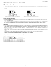
...be apt to turn on the PWB silk. As the melting point of lead-free solder (Sn-Ag-Cu) is alloyed with the PWB for servicing PARTS CODE ZHNDAi123250E ZHNDAi126500E ZHNDAi12801KE PRICE RANK BL BK BM PART DELIVERY J ...use of the bit as you may be exceeded, remove the bit from the PWB as soon as required. Repairing with the lead-free solder, apply lead-free wire solder. If a different type of this model employs lead-free solder. PRECAUTIONS FOR USING LEAD-FREE SOLDER LC-C3742U „Employing lead-free solder • "PWBs" of solder stays on the PWBs and service manuals...
...be apt to turn on the PWB silk. As the melting point of lead-free solder (Sn-Ag-Cu) is alloyed with the PWB for servicing PARTS CODE ZHNDAi123250E ZHNDAi126500E ZHNDAi12801KE PRICE RANK BL BK BM PART DELIVERY J ...use of the bit as you may be exceeded, remove the bit from the PWB as soon as required. Repairing with the lead-free solder, apply lead-free wire solder. If a different type of this model employs lead-free solder. PRECAUTIONS FOR USING LEAD-FREE SOLDER LC-C3742U „Employing lead-free solder • "PWBs" of solder stays on the PWBs and service manuals...

Service Manual
Page 6
LC-C3742U PRECAUTIONS IN SERVICING THE HDCP-KEY ROM Applied part: HDCP-KEY ROM IC8451 RH-IXB979WJQZY (updated ROM) The HDCP-KEY ROM shall be protected and managed for its information inside. In servicing this ROM, therefore, take the following information protection/management measures. 1) When disposing of the component parts and PWBs, destruct the IC itself in a proper way...
LC-C3742U PRECAUTIONS IN SERVICING THE HDCP-KEY ROM Applied part: HDCP-KEY ROM IC8451 RH-IXB979WJQZY (updated ROM) The HDCP-KEY ROM shall be protected and managed for its information inside. In servicing this ROM, therefore, take the following information protection/management measures. 1) When disposing of the component parts and PWBs, destruct the IC itself in a proper way...

Service Manual
Page 7
... LC-C3742U PARTS GUIDE No. This document has been published to change without notice. MODEL LC-C3742U CONTENTS [1] CABINET AND MECHANICAL PARTS [2] SUPPLIED ACCESSORIES REPLACEMENT ITEM) [4] SERVICE JIGS (USE FOR SERVICING) [3] PACKING PARTS (NOT Parts marked with specified ones for maintaining the safety and performance of the set . SX6Y7LCC3742U Note: The reference numbers on the PWB are important for after sales service only. The contents are subject to be used...
... LC-C3742U PARTS GUIDE No. This document has been published to change without notice. MODEL LC-C3742U CONTENTS [1] CABINET AND MECHANICAL PARTS [2] SUPPLIED ACCESSORIES REPLACEMENT ITEM) [4] SERVICE JIGS (USE FOR SERVICING) [3] PACKING PARTS (NOT Parts marked with specified ones for maintaining the safety and performance of the set . SX6Y7LCC3742U Note: The reference numbers on the PWB are important for after sales service only. The contents are subject to be used...

Service Manual
Page 9
... AA AA AA AA AB AB AD AG N BQ N - Badge, SHARP X SP-Net J Spacer, x2 - Rug Angle Bottom LR J Wire Holder LC-C3742U 3 LED Cover - Operation Button J 37" WIDE LCD Panel Module Unit X MAIN Shield Ass'y - Tray Chassis J Wire Holder, x3 J Wire Holder - N - N AB X Front Cabinet Ass'y - Front Cabinet - PARTS CODE PRICE NEW PART RANK MARK DELIVERY DESCRIPTION [1] CABINET AND MECHANICAL...
... AA AA AA AA AB AB AD AG N BQ N - Badge, SHARP X SP-Net J Spacer, x2 - Rug Angle Bottom LR J Wire Holder LC-C3742U 3 LED Cover - Operation Button J 37" WIDE LCD Panel Module Unit X MAIN Shield Ass'y - Tray Chassis J Wire Holder, x3 J Wire Holder - N - N AB X Front Cabinet Ass'y - Front Cabinet - PARTS CODE PRICE NEW PART RANK MARK DELIVERY DESCRIPTION [1] CABINET AND MECHANICAL...

Service Manual
Page 12
... J Connecting Cord (PE (PA) 12pin 100cm) MAIN to POWER Unit J Connecting Cord (PD (MI) 6pin 100cm) MAIN to POWER Unit J Connecting Cord (LA/LB 4p-8p 130cm) MAIN to INVERTER Unit Connecting Cord (LA 10p-14p 100cm) POWER to INVERTER Unit J Connecting Cord (LV 30pin 100cm) MAIN to LCD CONTROL Unit J Connecting Cord (SH 7pin 100cm) MAIN to LCD CONTROL Unit 6 Polyethylene Bag Polyethylene Bag Polyethylene Bag (for Screw) No. LC-C3742U...
... J Connecting Cord (PE (PA) 12pin 100cm) MAIN to POWER Unit J Connecting Cord (PD (MI) 6pin 100cm) MAIN to POWER Unit J Connecting Cord (LA/LB 4p-8p 130cm) MAIN to INVERTER Unit Connecting Cord (LA 10p-14p 100cm) POWER to INVERTER Unit J Connecting Cord (LV 30pin 100cm) MAIN to LCD CONTROL Unit J Connecting Cord (SH 7pin 100cm) MAIN to LCD CONTROL Unit 6 Polyethylene Bag Polyethylene Bag Polyethylene Bag (for Screw) No. LC-C3742U...

Service Manual
Page 13
MEMO LC-C3742U COPYRIGHT © XXXX BYSHARP CORPORATION ALL RIGHTS RESERVED. No part of this publication may be reproduced, stored in a retrieval system, or transmitted in any form or by any means, electronic, mechanical, photocopying, recording, or otherwise, without prior written permission of the publisher.
MEMO LC-C3742U COPYRIGHT © XXXX BYSHARP CORPORATION ALL RIGHTS RESERVED. No part of this publication may be reproduced, stored in a retrieval system, or transmitted in any form or by any means, electronic, mechanical, photocopying, recording, or otherwise, without prior written permission of the publisher.

Service Manual
Page 14
KD SHARP CORPORATION AV Systems Group CS Promotion Center Yaita, Tochigi 329-2193, Japan No part of the publisher. Jan. 2007 Printed in any form or by any means, electronic, mechanical, photocopying, recording, or otherwise, without prior written permission of this publication may be reproduced, stored in a retrieval system, or transmitted in Japan TQ2101-S MI. LC-C3742U COPYRIGHT 2007 BY SHARP CORPORATION ALL RIGHTS RESERVED.
KD SHARP CORPORATION AV Systems Group CS Promotion Center Yaita, Tochigi 329-2193, Japan No part of the publisher. Jan. 2007 Printed in any form or by any means, electronic, mechanical, photocopying, recording, or otherwise, without prior written permission of this publication may be reproduced, stored in a retrieval system, or transmitted in Japan TQ2101-S MI. LC-C3742U COPYRIGHT 2007 BY SHARP CORPORATION ALL RIGHTS RESERVED.
Service Manual
Page 15
... been published to change without notice. OUTLINE In this Service Manual, only parts in some countries) the set . Be sure to replace these parts with " " are subject to be used for maintaining the safety and performance of user-safety (Required by safety regulations in the LCD module are shown. TopPage LC-37D42U/LC-37D43U/LC-C3742U SERVICE MANUAL No. S47G2LC37D42U SUPPLEMENT LCD COLOR TELEVISION LC-37D42U LC-37D43U MODELS LC-C3742U In the interests...
... been published to change without notice. OUTLINE In this Service Manual, only parts in some countries) the set . Be sure to replace these parts with " " are subject to be used for maintaining the safety and performance of user-safety (Required by safety regulations in the LCD module are shown. TopPage LC-37D42U/LC-37D43U/LC-C3742U SERVICE MANUAL No. S47G2LC37D42U SUPPLEMENT LCD COLOR TELEVISION LC-37D42U LC-37D43U MODELS LC-C3742U In the interests...

Service Manual
Page 16
... AND ADJUSTMENT Service Manual [1] Outline In this Service Manual, only parts in the LCD module are shown. For the other points, refer to the LC-37D42U/LC-37D43U/LC-C3742U (S06X9LC32D42U/SX6Y9LC37D43U/SX6Y7LCC3742U) Service Manual. [2] Adjustment When replacing the LCD control PCB, follow these steps to adjust VCOM. 1) Remove the wire from the LCD control PCB CN3. 2) Connect a wire of the VCOM adjustment jig (electronic volume adjustment BOX) to CN3 (see Fig. 1). 3) Turn on the TV set. 4) Turn on...
... AND ADJUSTMENT Service Manual [1] Outline In this Service Manual, only parts in the LCD module are shown. For the other points, refer to the LC-37D42U/LC-37D43U/LC-C3742U (S06X9LC32D42U/SX6Y9LC37D43U/SX6Y7LCC3742U) Service Manual. [2] Adjustment When replacing the LCD control PCB, follow these steps to adjust VCOM. 1) Remove the wire from the LCD control PCB CN3. 2) Connect a wire of the VCOM adjustment jig (electronic volume adjustment BOX) to CN3 (see Fig. 1). 3) Turn on the TV set. 4) Turn on...

Service Manual
Page 17
The contents are important for maintaining the safety of the set . PartsGuide LC-37D42U/LC-37D43U/LC-C3742U PARTS GUIDE LCD COLOR TELEVISION LC-37D42U LC-37D43U MODELS LC-C3742U CONTENTS [1] LCD MODULE Assembly Parts marked with specified ones for maintaining the safety and performance of the set . This document has been published to change without notice. Be sure to replace these parts with " " are subject to be used for after sales service only.
The contents are important for maintaining the safety of the set . PartsGuide LC-37D42U/LC-37D43U/LC-C3742U PARTS GUIDE LCD COLOR TELEVISION LC-37D42U LC-37D43U MODELS LC-C3742U CONTENTS [1] LCD MODULE Assembly Parts marked with specified ones for maintaining the safety and performance of the set . This document has been published to change without notice. Be sure to replace these parts with " " are subject to be used for after sales service only.
Service Manual
Page 19
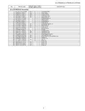
PARTS CODE PRICE NEW PART RANK MARK DELIVERY DESCRIPTION [1] LCD MODULE Assembly 1 ...N N BR N AK N AB N N AC N N AA AA AA AA J LCD Module Ass'y J Vessel (Top) J Vessel (Bottom) J Vessel (L, R), x2 J Panel Holder Ass'y J Spacer Ass'y, x2 J Reflection Sheet, x2 J Diffusion Panel J Lamp Holder-L J Lamp Holder-R J Lamp Unit, x9 J Lamp Holder (Bottom), ... B J Shield Plate (for Inverter) J LCD CONTROL Unit J Shield Plate (for LCD CONTROL Unit) J Spacer, x6 J CS-FPC1, x2 J Clip, x4 J Screw, x8 J Screw, x10 J Screw, x12 J Screw, x12 J Screw, x4 3 LC-37D42U/LC-37D43U/LC-C3742U NO.
PARTS CODE PRICE NEW PART RANK MARK DELIVERY DESCRIPTION [1] LCD MODULE Assembly 1 ...N N BR N AK N AB N N AC N N AA AA AA AA J LCD Module Ass'y J Vessel (Top) J Vessel (Bottom) J Vessel (L, R), x2 J Panel Holder Ass'y J Spacer Ass'y, x2 J Reflection Sheet, x2 J Diffusion Panel J Lamp Holder-L J Lamp Holder-R J Lamp Unit, x9 J Lamp Holder (Bottom), ... B J Shield Plate (for Inverter) J LCD CONTROL Unit J Shield Plate (for LCD CONTROL Unit) J Spacer, x6 J CS-FPC1, x2 J Clip, x4 J Screw, x8 J Screw, x10 J Screw, x12 J Screw, x12 J Screw, x4 3 LC-37D42U/LC-37D43U/LC-C3742U NO.

Service Manual
Page 20
No Part of this publication may be reproduced, stored in a retrieval system, or transmitted in any from or by any means, electronic, mechanical, photocopying, recording, or otherwise, without prior written permission of the publisher. TQ2186-S YT. DS SHARP CORPORATION AV Systems Group CS Promotion Center Yaita,Tochigi 329-2193, Japan LC-37D42U/LC-37D43U/LC-C3742U COPYRIGHT © 2007 BY SHARP CORPORATION ALL RIGHTS RESERVED.
No Part of this publication may be reproduced, stored in a retrieval system, or transmitted in any from or by any means, electronic, mechanical, photocopying, recording, or otherwise, without prior written permission of the publisher. TQ2186-S YT. DS SHARP CORPORATION AV Systems Group CS Promotion Center Yaita,Tochigi 329-2193, Japan LC-37D42U/LC-37D43U/LC-C3742U COPYRIGHT © 2007 BY SHARP CORPORATION ALL RIGHTS RESERVED.


