
Service Manual
Page 1
PRINTED WIRING BOARD [1] AV TERMINAL UNIT PRINTED WIRING BOARD 6-1 CHAPTER 7. TopPage SUPPLEMENT ATTACHED LC-52D43U SERVICE MANUAL No. TROUBLESHOOTING TABLE [1] TROUBLESHOOTING TABLE 4-1 CHAPTER 5. OVERALL WIRING DIAGRAM/BLOCK DIAGRAM [1] OVERALL WIRING DIAGRAM 5-1 [2] SYSTEM BLOCK DIAGRAM...PARTS [1] REMOVING OF MAJOR PARTS 2-1 CHAPTER 3. This document has been published to those specified should be used. S87P2LC52D43U LCD COLOR TELEVISION MODEL LC-52D43U In the interests of the set should be restored to its original condition and only parts identical to be used for ...
PRINTED WIRING BOARD [1] AV TERMINAL UNIT PRINTED WIRING BOARD 6-1 CHAPTER 7. TopPage SUPPLEMENT ATTACHED LC-52D43U SERVICE MANUAL No. TROUBLESHOOTING TABLE [1] TROUBLESHOOTING TABLE 4-1 CHAPTER 5. OVERALL WIRING DIAGRAM/BLOCK DIAGRAM [1] OVERALL WIRING DIAGRAM 5-1 [2] SYSTEM BLOCK DIAGRAM...PARTS [1] REMOVING OF MAJOR PARTS 2-1 CHAPTER 3. This document has been published to those specified should be used. S87P2LC52D43U LCD COLOR TELEVISION MODEL LC-52D43U In the interests of the set should be restored to its original condition and only parts identical to be used for ...

Service Manual
Page 2
... POWER Unit LC-32D42U/37D42U (Base Model) LC-52D43U DUNTKD909FM02 DUNTKD910FM02 DUNTKD999FM04 DUNTKD862FM04 RDENCA198WJQZ DUNTKD909FM02 DUNTKD910FM02 DUNTKD935FM02 DUNTKD862FM07 RDENCA184WJQZ Remark No Change No Change Change Change Unit Replacement Item LCD PANEL (NOTE: THE PARTS HERE SHOWN ARE SUPPLIED AS AN ASSEMBLY BUT NOT INDEPENDENTLY.) 32" LCD Panel R1LK315T3LZ4BX Delete 37" LCD Panel R1LK370T3LZ5BW Delete 52" LCD Panel R1LK520T3LZ1AZ...
... POWER Unit LC-32D42U/37D42U (Base Model) LC-52D43U DUNTKD909FM02 DUNTKD910FM02 DUNTKD999FM04 DUNTKD862FM04 RDENCA198WJQZ DUNTKD909FM02 DUNTKD910FM02 DUNTKD935FM02 DUNTKD862FM07 RDENCA184WJQZ Remark No Change No Change Change Change Unit Replacement Item LCD PANEL (NOTE: THE PARTS HERE SHOWN ARE SUPPLIED AS AN ASSEMBLY BUT NOT INDEPENDENTLY.) 32" LCD Panel R1LK315T3LZ4BX Delete 37" LCD Panel R1LK370T3LZ5BW Delete 52" LCD Panel R1LK520T3LZ1AZ...
Service Manual
Page 5
... continued safety, no shock hazard exists, check for the purpose of 0.75 Vrms (this service manual, may create shock, fire or other metal parts in LCD color television have special safety-related characteristics. LSCA52FD4E3UTY PRECAUTION Service Manual LC-52D43U IMPORTANT SERVICE SAFETY PRECAUTION Service work should be attempted. 2.
... continued safety, no shock hazard exists, check for the purpose of 0.75 Vrms (this service manual, may create shock, fire or other metal parts in LCD color television have special safety-related characteristics. LSCA52FD4E3UTY PRECAUTION Service Manual LC-52D43U IMPORTANT SERVICE SAFETY PRECAUTION Service work should be attempted. 2.

Service Manual
Page 8
TV (Rear/Top) HDMI terminal (INPUT 4) HDMI terminal (INPUT 5) PC IN terminals (INPUT 6) Antenna/Cable in AUDIO terminals (INPUT 5) DIGITAL AUDIO OUTPUT terminal INPUT 3 terminals Remote control sensor OPC sensor* OPC indicator** SLEEP indicator** POWER indicator** Channel buttons (CH / ) Volume buttons (VOL / ) INPUT button POWER button INPUT 1 terminals INPUT 2 terminals AUDIO OUTPUT terminals AC INPUT terminal 1 - 2 LC-52D43U [2] OPERATION MANUAL Part names TV (Front) NOTE *OPC: Optical Picture Control. **TV status indicator.
TV (Rear/Top) HDMI terminal (INPUT 4) HDMI terminal (INPUT 5) PC IN terminals (INPUT 6) Antenna/Cable in AUDIO terminals (INPUT 5) DIGITAL AUDIO OUTPUT terminal INPUT 3 terminals Remote control sensor OPC sensor* OPC indicator** SLEEP indicator** POWER indicator** Channel buttons (CH / ) Volume buttons (VOL / ) INPUT button POWER button INPUT 1 terminals INPUT 2 terminals AUDIO OUTPUT terminals AC INPUT terminal 1 - 2 LC-52D43U [2] OPERATION MANUAL Part names TV (Front) NOTE *OPC: Optical Picture Control. **TV status indicator.

Service Manual
Page 9
... from a closed-caption source. 27 AV MODE: Select an audio or video setting. (When the input source is TV, INPUT 1, 2 or 3: STANDARD, MOVIE, GAME, USER, DYNAMIC (Fixed), DYNAMIC. LC-52D43U Part names Remote control unit 1 14 2 3 15 4 16 5 6 17 7 18 8 19 9 20 ...unit will turn off . 4 External equipment operational buttons: Operate the external equipment. 5 0 - 9: Set the channel. 6 • (DOT): 7 INPUT: Select a TV input source. (TV, INPUT 1, INPUT 2, INPUT 3, INPUT 4, INPUT 5, INPUT 6) 8 VOL / : Set the volume. 9 SURROUND: Select Surround settings. 10 FREEZE: Set the still...
... from a closed-caption source. 27 AV MODE: Select an audio or video setting. (When the input source is TV, INPUT 1, 2 or 3: STANDARD, MOVIE, GAME, USER, DYNAMIC (Fixed), DYNAMIC. LC-52D43U Part names Remote control unit 1 14 2 3 15 4 16 5 6 17 7 18 8 19 9 20 ...unit will turn off . 4 External equipment operational buttons: Operate the external equipment. 5 0 - 9: Set the channel. 6 • (DOT): 7 INPUT: Select a TV input source. (TV, INPUT 1, INPUT 2, INPUT 3, INPUT 4, INPUT 5, INPUT 6) 8 VOL / : Set the volume. 9 SURROUND: Select Surround settings. 10 FREEZE: Set the still...

Service Manual
Page 11
... bright? Check that is too bright. • Check the input signal setting. • Power is suddenly turned off /with new batteries.) LC-52D43U • Picture is not a malfunction. This is correctly setup. • Check the broadcast time in a hot or cold location. This ... • Check if you pressed MUTE on a screen • Failed to 60°C) 1 - 5 This does not affect the TV's performance. Cautions regarding use in temperature. Troubleshooting-Digital broadcasting The error message about reception of broadcast The example of an error message displayed on...
... bright? Check that is too bright. • Check the input signal setting. • Power is suddenly turned off /with new batteries.) LC-52D43U • Picture is not a malfunction. This is correctly setup. • Check the broadcast time in a hot or cold location. This ... • Check if you pressed MUTE on a screen • Failed to 60°C) 1 - 5 This does not affect the TV's performance. Cautions regarding use in temperature. Troubleshooting-Digital broadcasting The error message about reception of broadcast The example of an error message displayed on...

Service Manual
Page 15
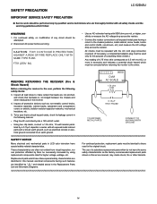
LCC5H2DA43PU TER 2. Remove the 4 lock screws 2 and detach the Stand. 3. Remove the 5 lock screws 3 . 4. Remove the 18 lock screws 4 and detach the Rear Cabinet. 4 SD Card Cover 1 3 3 2 2 Stand Rear Cabinet LC-52D43U 2 - 1 Detach the SD Card Cover 1 . 2. REMOVING OF MAJOR PARSTeSrvice Manual [1] REMOVING OF MAJOR PARTS 1.
LCC5H2DA43PU TER 2. Remove the 4 lock screws 2 and detach the Stand. 3. Remove the 5 lock screws 3 . 4. Remove the 18 lock screws 4 and detach the Rear Cabinet. 4 SD Card Cover 1 3 3 2 2 Stand Rear Cabinet LC-52D43U 2 - 1 Detach the SD Card Cover 1 . 2. REMOVING OF MAJOR PARSTeSrvice Manual [1] REMOVING OF MAJOR PARTS 1.
Service Manual
Page 16
Remove the 8 lock screws 5 8 lock point and detach the Stand St Cover-R. 6. Remove the 8 lock screws 6 and detach the Stand Fixing Angle. 8. Remove the 2 lock screws 7 . 9. LC-52D43U 5. Remove the 4 lock screws 8 and detach the Bridge Angle and Chassis Fixing Angle. 10.Remove the 7 lock screws 9 and detach the Main Shield. 8 Bridge Angle Bridge Angle 9 Chassis 8 Fixing Angle Main Shield Speaker Speaker 7 7 Stand Fixing Angle 6 6 Hook 5 Lock point Stand Assist Holder Stand St Cover-R Hook 5 Lock point 2 - 2 Remove the 4 hook and detach the Stand assist Holder. 7.
Remove the 8 lock screws 5 8 lock point and detach the Stand St Cover-R. 6. Remove the 8 lock screws 6 and detach the Stand Fixing Angle. 8. Remove the 2 lock screws 7 . 9. LC-52D43U 5. Remove the 4 lock screws 8 and detach the Bridge Angle and Chassis Fixing Angle. 10.Remove the 7 lock screws 9 and detach the Main Shield. 8 Bridge Angle Bridge Angle 9 Chassis 8 Fixing Angle Main Shield Speaker Speaker 7 7 Stand Fixing Angle 6 6 Hook 5 Lock point Stand Assist Holder Stand St Cover-R Hook 5 Lock point 2 - 2 Remove the 4 hook and detach the Stand assist Holder. 7.
Service Manual
Page 17
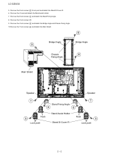
11.Disconnect all the connectors from all the PWBs. 12.Remove the 2 lock screws 10 and detach the KEY PWB. Top Cover KEY PWB 10 LV LV LC-52D43U 2 - 3
11.Disconnect all the connectors from all the PWBs. 12.Remove the 2 lock screws 10 and detach the KEY PWB. Top Cover KEY PWB 10 LV LV LC-52D43U 2 - 3

Service Manual
Page 18
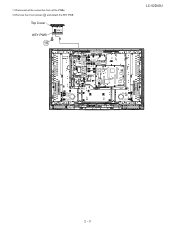
LC-52D43U 13.Remove the 9 lock screws 11 and detach the Tray Chassis. 14.Disconnect the 3 connectors (MA, FC, SA), and COAXIAL Wire. 15.Remove the 2 lock ...
LC-52D43U 13.Remove the 9 lock screws 11 and detach the Tray Chassis. 14.Disconnect the 3 connectors (MA, FC, SA), and COAXIAL Wire. 15.Remove the 2 lock ...
Service Manual
Page 19
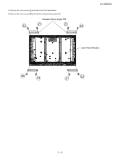
Chassis Fixing Angle T/B 22 21 21 22 LC-52D43U LCD Panel Module 22 21 21 22 2 - 5 21.Remove the 4 lock screws 21 and detach the LCD Panel Module. 22.Remove the 8 lock screws 22 and detach the Chassis Fixing Angle T/B.
Chassis Fixing Angle T/B 22 21 21 22 LC-52D43U LCD Panel Module 22 21 21 22 2 - 5 21.Remove the 4 lock screws 21 and detach the LCD Panel Module. 22.Remove the 8 lock screws 22 and detach the Chassis Fixing Angle T/B.

Service Manual
Page 20
...to their reference levels. AV TERMINAL Unit: DUNTKD935FM01 2. Correct the G setting (512 x 6th- Correct the G setting (192 x 6th- LC-52D43U LCC5H2DA43PU TER 3. ADJUSTMENT Service Manual [1] ADJUSTMENT PROCEDURE The adjustment values are set to the optimum conditions at each point.) (WBI50800) [Adjustment ...value] MG5G**** MG5B**** • As per the "standard set" submitted by Engineering Department "LC-52D43U" Teaching set at 920 * Initial R, G and B settings at points 1 thru 5: Corrected G setting at each point Point 5...
...to their reference levels. AV TERMINAL Unit: DUNTKD935FM01 2. Correct the G setting (512 x 6th- Correct the G setting (192 x 6th- LC-52D43U LCC5H2DA43PU TER 3. ADJUSTMENT Service Manual [1] ADJUSTMENT PROCEDURE The adjustment values are set to the optimum conditions at each point.) (WBI50800) [Adjustment ...value] MG5G**** MG5B**** • As per the "standard set" submitted by Engineering Department "LC-52D43U" Teaching set at 920 * Initial R, G and B settings at points 1 thru 5: Corrected G setting at each point Point 5...

Service Manual
Page 21
..., write the EDID data for inspection AV MODE: [DYNAMIC] (Reset) Monochrome: ON Black: OFF Color Temp: High Back Light: +16 Aging Time: Min. 60 minutes LC-52D43U 2.2. TL1514: I2C clock, TL1515: I2C data TL1516: 5V, TL1517: GND TL1502: VCLK (Write: H, Read: V pulse) 2) In the analog RGB inspection, use a DDC-compatible device...
..., write the EDID data for inspection AV MODE: [DYNAMIC] (Reset) Monochrome: ON Black: OFF Color Temp: High Back Light: +16 Aging Time: Min. 60 minutes LC-52D43U 2.2. TL1514: I2C clock, TL1515: I2C data TL1516: 5V, TL1517: GND TL1502: VCLK (Write: H, Read: V pulse) 2) In the analog RGB inspection, use a DDC-compatible device...
Service Manual
Page 22
... are set the following value to the G adjustment value of gradation 6) * Make sure the adjusting point gradations are correct since they are different for 45). LC-52D43U 2. Repeat until RGB become the target values. The adjustment value is done. SBSL0016 Setting is changed at gradation 6, calculate the ratio of the WBI6 command...
... are set the following value to the G adjustment value of gradation 6) * Make sure the adjusting point gradations are correct since they are different for 45). LC-52D43U 2. Repeat until RGB become the target values. The adjustment value is done. SBSL0016 Setting is changed at gradation 6, calculate the ratio of the WBI6 command...

Service Manual
Page 23
... values are set with WBI4) x 2 x (the ratio). OK Start measurement Repeat until RGB become the target values. Adjust RB to the target xy values. OK LC-52D43U 3 - 4 OK Correction of G value MG4GXXXX When G is the parameter value of the change and set the following value to XXXX: (the value set . MG4RXXXX MG4BXXXX...
... values are set with WBI4) x 2 x (the ratio). OK Start measurement Repeat until RGB become the target values. Adjust RB to the target xy values. OK LC-52D43U 3 - 4 OK Correction of G value MG4GXXXX When G is the parameter value of the change and set the following value to XXXX: (the value set . MG4RXXXX MG4BXXXX...

Service Manual
Page 24
... XXXX: (the value set with zero fill). * G is fixed. * The default adjustment value of RGB is the parameter value of the WBI2 command multiplied by 2. LC-52D43U PC Set Start measurement Repeat until RGB become the target values. Adjust RB to the target xy values. Adjust RB to the target xy values...
... XXXX: (the value set with zero fill). * G is fixed. * The default adjustment value of RGB is the parameter value of the WBI2 command multiplied by 2. LC-52D43U PC Set Start measurement Repeat until RGB become the target values. Adjust RB to the target xy values. Adjust RB to the target xy values...

Service Manual
Page 25
... multiplied by 2. Adjustment values are set. PC Set Start measurement Repeat until RGB become the target values. Adjust RB to the target xy values. OK LC-52D43U 2.3. Menu list in the image. MG1RXXXX MG1BXXXX * XXXX indicates the adjusted values between 0000 and 1023 (4 digit decimal number with zero fill). * G is fixed. * The...
... multiplied by 2. Adjustment values are set. PC Set Start measurement Repeat until RGB become the target values. Adjust RB to the target xy values. OK LC-52D43U 2.3. Menu list in the image. MG1RXXXX MG1BXXXX * XXXX indicates the adjusted values between 0000 and 1023 (4 digit decimal number with zero fill). * G is fixed. * The...

Service Manual
Page 26
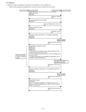
...Is audio input from pins 38 and 39 of IC1404 to pin 21 of IC2701(STEREO_AMP) normal? YES Check IC1404 and peripheral circuits. LC-52D43U LCC5H2DA43PU TER 4. NO Check the tuner and peripheral circuits. NO Are the DSP_LRCK, DSP_BCKIN, DSP_SDIN1, DSP_MCLK, DSP_SDOUT1, DSP_SDOUT2 signals sent ...circuits. TROUBLESHOOTING TABLEService Manual [1] TROUBLESHOOTING TABLE No audio output during UHF/VHF reception Is SIF output from IC1404 to pins 51 and 52 of IC1404 normal? YES Is audio output from pins 29 and 30 of IC1401 to IC1407 (DSP) normally? YES Reset monitor...
...Is audio input from pins 38 and 39 of IC1404 to pin 21 of IC2701(STEREO_AMP) normal? YES Check IC1404 and peripheral circuits. LC-52D43U LCC5H2DA43PU TER 4. NO Check the tuner and peripheral circuits. NO Are the DSP_LRCK, DSP_BCKIN, DSP_SDIN1, DSP_MCLK, DSP_SDOUT1, DSP_SDOUT2 signals sent ...circuits. TROUBLESHOOTING TABLEService Manual [1] TROUBLESHOOTING TABLE No audio output during UHF/VHF reception Is SIF output from IC1404 to pins 51 and 52 of IC1404 normal? YES Is audio output from pins 29 and 30 of IC1401 to IC1407 (DSP) normally? YES Reset monitor...

Service Manual
Page 27
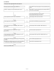
... signal fed from input terminal J502 to pin 54 of IC1404? YES Check the connector (P2703) of IC1404 normal? No audio output from external input LC-52D43U [INPUT-4/INPUT5 (Digital audio mode)] Is digital audio signal (DTV_SPDIF) fed from pin E12 of IC8101 to pin 4 of IC1404? [INPUT-5 (Analog audio mode)] Is...
... signal fed from input terminal J502 to pin 54 of IC1404? YES Check the connector (P2703) of IC1404 normal? No audio output from external input LC-52D43U [INPUT-4/INPUT5 (Digital audio mode)] Is digital audio signal (DTV_SPDIF) fed from pin E12 of IC8101 to pin 4 of IC1404? [INPUT-5 (Analog audio mode)] Is...
Service Manual
Page 28
... (COMOS) signal sent from pins 37-42 and 45-48 of IC501? YES Is video signal sent to pin 60 of IC2602? composed of IC501. LC-52D43U No video output (1) No video output from external input Is INPUT-1 selected on the input switching menu screen? Check between IC501 and SC501. (Q501, Q502...
... (COMOS) signal sent from pins 37-42 and 45-48 of IC501? YES Is video signal sent to pin 60 of IC2602? composed of IC501. LC-52D43U No video output (1) No video output from external input Is INPUT-1 selected on the input switching menu screen? Check between IC501 and SC501. (Q501, Q502...


