Service Manual
Page 2
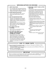
...on the cabinet, chassis and parts. USE THE DESIGNATED PARTS The parts in the condition that . (INSULATION CHECK PROCEDURE) 1. BE CAREFUL WITH THE LCD PANEL Avoid a shock to the IC and Transistor). The inside wiring is a high voltage part inside. PUT PARTS AND WIRES IN THE ORIGINAL ... positions, or whether there are the portions which were removed in order to deal with a heat sink, apply silicon grease (YG6260M) on the TV. 3. PART NO. Avoid an electric shock while the electric current is indicated in the operation manual. 2. A1-1 Insulation resistance between the antenna ...
...on the cabinet, chassis and parts. USE THE DESIGNATED PARTS The parts in the condition that . (INSULATION CHECK PROCEDURE) 1. BE CAREFUL WITH THE LCD PANEL Avoid a shock to the IC and Transistor). The inside wiring is a high voltage part inside. PUT PARTS AND WIRES IN THE ORIGINAL ... positions, or whether there are the portions which were removed in order to deal with a heat sink, apply silicon grease (YG6260M) on the TV. 3. PART NO. Avoid an electric shock while the electric current is indicated in the operation manual. 2. A1-1 Insulation resistance between the antenna ...
Service Manual
Page 4
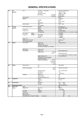
... System Speaker Sound Output Broadcasting System Tuner and Receive CH Intermediate Frequency Digital Analog Preset CH Stereo/Dual TV Sound Tuner Sound Muting Video Signal LCD Size / Visual Size LCD Type Number of Pixels View Range Left/Right Up/Down Position Size Impedance Max 10%(Typical) Analog Digital ...up (at 120V 60Hz Yes -- kWh/Year Yes Yes Yes UL/CSA/NOM FCC/IC -- 0oC ~ +40oC -20oC ~ +60oC Less than 26.0 inch / 660.53mmV Color TFT LCD 1366(H) x 768(V) 85/85 degree 85/85 degree NTSC 2 Speaker Front 2.2 x 5.0 inch 4 ohm 10W + 10W --- Min Sec A2-1
... System Speaker Sound Output Broadcasting System Tuner and Receive CH Intermediate Frequency Digital Analog Preset CH Stereo/Dual TV Sound Tuner Sound Muting Video Signal LCD Size / Visual Size LCD Type Number of Pixels View Range Left/Right Up/Down Position Size Impedance Max 10%(Typical) Analog Digital ...up (at 120V 60Hz Yes -- kWh/Year Yes Yes Yes UL/CSA/NOM FCC/IC -- 0oC ~ +40oC -20oC ~ +60oC Less than 26.0 inch / 660.53mmV Color TFT LCD 1366(H) x 768(V) 85/85 degree 85/85 degree NTSC 2 Speaker Front 2.2 x 5.0 inch 4 ohm 10W + 10W --- Min Sec A2-1
Service Manual
Page 6
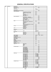
... GENERAL SPECIFICATIONS Auto Shut Off Auto Search Power On Memory Comb Filter Game Position Auto Setup(Language/CH Program) Picture Setting(TV) AV Mode(Picture Preference) Brightness , Contrast , Color Tint Sharpness Color Temperature Cable Clear Picture Setting(PC) BRIGHTNESS , CONTRAST HOR POSITION , VER POSITION PHASE , CLOCK AUTO ADJUST RED , GREEN , BLUE Audio...
... GENERAL SPECIFICATIONS Auto Shut Off Auto Search Power On Memory Comb Filter Game Position Auto Setup(Language/CH Program) Picture Setting(TV) AV Mode(Picture Preference) Brightness , Contrast , Color Tint Sharpness Color Temperature Cable Clear Picture Setting(PC) BRIGHTNESS , CONTRAST HOR POSITION , VER POSITION PHASE , CLOCK AUTO ADJUST RED , GREEN , BLUE Audio...
Service Manual
Page 13
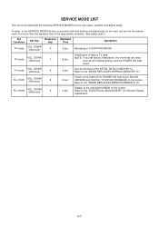
... Time Operations 2 sec. Releasing of MEMORY IC. Can be checked of the INITIAL DATA of V-CHIP PASSWORD. Display of the Adjustment MENU on the screen. TV mode VOL. ALL mode VOL. DOWN (Minimum) 8 2 sec. ALL mode VOL. DOWN (Minimum) 9 2 sec. NOTE: If you can repair, examine and ... the remote control for more than the standard time in the appropriate condition. (See below chart.) Set Condition Set Key Remocon Key TV mode VOL. SERVICE MODE LIST This unit is provided with the following SERVICE MODES so you set factory initialization, the memories are reset...
... Time Operations 2 sec. Releasing of MEMORY IC. Can be checked of the INITIAL DATA of V-CHIP PASSWORD. Display of the Adjustment MENU on the screen. TV mode VOL. ALL mode VOL. DOWN (Minimum) 8 2 sec. ALL mode VOL. DOWN (Minimum) 9 2 sec. NOTE: If you can repair, examine and ... the remote control for more than the standard time in the appropriate condition. (See below chart.) Set Condition Set Key Remocon Key TV mode VOL. SERVICE MODE LIST This unit is provided with the following SERVICE MODES so you set factory initialization, the memories are reset...
Service Manual
Page 14
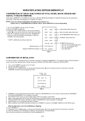
...Channel button (1) on the remote, step through the DATA using UP/DOWN button until all data has been checked. 9. ADDRESS DATA INIT 0000 00 LCD ON 0000 OEC7154B_010 DTV d0l63041 FIG. 2 4. ADDRESS is selected, it has been required to change the MEMORY IC, the following steps should be...off (return to STANDBY MODE) to ADDRESS for more than 2 seconds. 4. Press both VOL. MICON Version Digital TV MICON Firmware INIT : C66D ROM : 0000 ADC : 8F97 DVP1 : F8B4 *1 DVP2 : 2D23 LCD ON 0000 OEC7154B_010 DTV d0l63041 FIG. 1 Initial setting data check sum. Turn POWER on the screen. The unit ...
...Channel button (1) on the remote, step through the DATA using UP/DOWN button until all data has been checked. 9. ADDRESS DATA INIT 0000 00 LCD ON 0000 OEC7154B_010 DTV d0l63041 FIG. 2 4. ADDRESS is selected, it has been required to change the MEMORY IC, the following steps should be...off (return to STANDBY MODE) to ADDRESS for more than 2 seconds. 4. Press both VOL. MICON Version Digital TV MICON Firmware INIT : C66D ROM : 0000 ADC : 8F97 DVP1 : F8B4 *1 DVP2 : 2D23 LCD ON 0000 OEC7154B_010 DTV d0l63041 FIG. 1 Initial setting data check sum. Turn POWER on the screen. The unit ...
Service Manual
Page 16
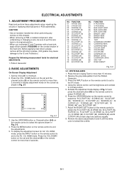
TV 01 H POSI OSD 346 Fig. 2-1 3. Press the VOL.DOWN button on the set to normal position. 5. FUNCTION 22 H POSI 60Hz 24 V POSI 60Hz 25 BAK LIGHT CENT 26 BAK LIGHT MAX 27 BAK LIGHT MIN 28 BRIGHT CENT 29 BRIGHT MAX 30 BRIGHT MIN 31 TINT 35 CONTRAST CENTER 36 CONTRAST MAX...
TV 01 H POSI OSD 346 Fig. 2-1 3. Press the VOL.DOWN button on the set to normal position. 5. FUNCTION 22 H POSI 60Hz 24 V POSI 60Hz 25 BAK LIGHT CENT 26 BAK LIGHT MAX 27 BAK LIGHT MIN 28 BRIGHT CENT 29 BRIGHT MAX 30 BRIGHT MIN 31 TINT 35 CONTRAST CENTER 36 CONTRAST MAX...

Service Manual
Page 17
...of Fixed Value (Step No.) Please check if the fixed values of each of the adjustment items are set correctly referring below. (TV/AV/CS/HD-MI) CS HD-MI TV TV 720p AV AV (S) 480i 480p 720p 1080i 480i 480p 720p 1080i VGA NO. Step No. 1 H POSI OSD 346 346 ...--- 20 20 --- --- 20 66 SRC TOP(ZOOM) 43 43 43 43 43 43 --- --- 43 43 --- --- 43 66 SRC TOP(S.STRECH) 26 26 26 26 26 26 --- --- 26 26 --- --- 26 67 DEFA VIMGVT(STRECH) 20 25 20 20 20 43 26 24 20 44 32 24 42 67 DEFA VIMGVT(SIDE BAR) 20 25 20 20 20 43 --- --- 20 43 --- --- 42...
...of Fixed Value (Step No.) Please check if the fixed values of each of the adjustment items are set correctly referring below. (TV/AV/CS/HD-MI) CS HD-MI TV TV 720p AV AV (S) 480i 480p 720p 1080i 480i 480p 720p 1080i VGA NO. Step No. 1 H POSI OSD 346 346 ...--- 20 20 --- --- 20 66 SRC TOP(ZOOM) 43 43 43 43 43 43 --- --- 43 43 --- --- 43 66 SRC TOP(S.STRECH) 26 26 26 26 26 26 --- --- 26 26 --- --- 26 67 DEFA VIMGVT(STRECH) 20 25 20 20 20 43 26 24 20 44 32 24 42 67 DEFA VIMGVT(SIDE BAR) 20 25 20 20 20 43 --- --- 20 43 --- --- 42...


