

Service Manual
Page 1
... ...13-1 MECHANICAL PARTS LIST ...14-1 ELECTRICAL PARTS LIST ...15-1 This document has been published to change without notice. SERVICE MANUAL LCD COLOR TV LC-15AV7U SERVICE MANUAL S17F1LC15AV7U LCD COLOR TV MODEL LC-15AV7U In the interests of user-safety (Required by safety regulations in some countries) the set should be restored to its original condition...
... ...13-1 MECHANICAL PARTS LIST ...14-1 ELECTRICAL PARTS LIST ...15-1 This document has been published to change without notice. SERVICE MANUAL LCD COLOR TV LC-15AV7U SERVICE MANUAL S17F1LC15AV7U LCD COLOR TV MODEL LC-15AV7U In the interests of user-safety (Required by safety regulations in some countries) the set should be restored to its original condition...

Service Manual
Page 4
...an instrument to the customer, always make you, the servicer, responsible for personal injury or property damage resulting therefrom. 2-1 LCVISP Do not operate this TV receiver. Servicers who defeat safety features or fail to perform safety checks may make a safety check of the entire instrument, including, but are not limited... an adult or child might alter the safety characteristics of this test with American National Standards Institute (ANSI) C101.1 Leakage Current for LCD TV Circuit 1. If the measured resistance is being serviced. Antenna Cold Check - d.
...an instrument to the customer, always make you, the servicer, responsible for personal injury or property damage resulting therefrom. 2-1 LCVISP Do not operate this TV receiver. Servicers who defeat safety features or fail to perform safety checks may make a safety check of the entire instrument, including, but are not limited... an adult or child might alter the safety characteristics of this test with American National Standards Institute (ANSI) C101.1 Leakage Current for LCD TV Circuit 1. If the measured resistance is being serviced. Antenna Cold Check - d.

Service Manual
Page 15
D3 4-4 A7121DC TV Cable Wiring Diagram Function CBA CL1107 To LCD Module Main CBA To LCD Module CN401 CN403 CN1301 CN1402 CN1411 CN1401 LVDS CBA Unit CN1202 CN1201 Junction-A CBA CL801 CN801 To Speaker CN1302 CL1104 IR Sensor CBA CN62 CN61 CN102 CN101 CN802 Junction-B CBA CL802 DTV Module CBA Unit To Speaker Fig.
D3 4-4 A7121DC TV Cable Wiring Diagram Function CBA CL1107 To LCD Module Main CBA To LCD Module CN401 CN403 CN1301 CN1402 CN1411 CN1401 LVDS CBA Unit CN1202 CN1201 Junction-A CBA CL801 CN801 To Speaker CN1302 CL1104 IR Sensor CBA CN62 CN61 CN102 CN101 CN802 Junction-B CBA CL802 DTV Module CBA Unit To Speaker Fig.

Service Manual
Page 16
... Generator (Color Bar W/White Win- Press the number after [MENU] on the table to enter the service mode: Press [MENU] and [POWER] buttons on the TV unit simultaneously in the standby mode. 1. ITEM NOTE: Electrical adjustments are required after all repairs and replacements have been completed. Initial Setting General : Enter service...
... Generator (Color Bar W/White Win- Press the number after [MENU] on the table to enter the service mode: Press [MENU] and [POWER] buttons on the TV unit simultaneously in the standby mode. 1. ITEM NOTE: Electrical adjustments are required after all repairs and replacements have been completed. Initial Setting General : Enter service...

Service Manual
Page 17
... when replacing the LCD Panel then adjust as shown above signal. 2. [RF/INPUT1] Press [MENU] button on the remote control unit and press [1] on the TV unit.) 3. Press [1] button to "1. Refer to select "COR(C/D1)" for Blue adjustment. Symptom of Misadjustment: White becomes bluish or reddish. L = 3 cm INPUT: WHITE 80%, 20...
... when replacing the LCD Panel then adjust as shown above signal. 2. [RF/INPUT1] Press [MENU] button on the remote control unit and press [1] on the TV unit.) 3. Press [1] button to "1. Refer to select "COR(C/D1)" for Blue adjustment. Symptom of Misadjustment: White becomes bluish or reddish. L = 3 cm INPUT: WHITE 80%, 20...
Service Manual
Page 18
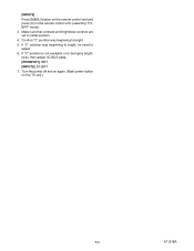
Confirm "C" position was beginning to bright, no need to bright. 5. If "C" position was beginning to adjust. 6. [INPUT2] Press [MENU] button on the remote control unit and press [3] on the TV unit.) 5-3 A7121EA Turn the power off and on again. (Main power button on the remote control unit. (selecting "D1BRT" mode). 3. Make sure that contrast and brightness controls are set to be highly brightness, then adjust IIC-BUS dada. [RF/INPUT1]: BRT [INPUT2]: D1-BRT 7. If "C" position is not available or to initial position. 4.
Confirm "C" position was beginning to bright, no need to bright. 5. If "C" position was beginning to adjust. 6. [INPUT2] Press [MENU] button on the remote control unit and press [3] on the TV unit.) 5-3 A7121EA Turn the power off and on again. (Main power button on the remote control unit. (selecting "D1BRT" mode). 3. Make sure that contrast and brightness controls are set to be highly brightness, then adjust IIC-BUS dada. [RF/INPUT1]: BRT [INPUT2]: D1-BRT 7. If "C" position is not available or to initial position. 4.

Service Manual
Page 19
To initialize the LCD television, press [DISPLAY] button on the upper right of the screen. 6-1 A7121INT Confirm "FF" indication on the remote control unit. 3. HOW TO INITIALIZE THE LCD TELEVISION 1. To enter the service mode, press [MENU] and [POWER] buttons on the TV unit simultaneously in the standby mode. 2.
To initialize the LCD television, press [DISPLAY] button on the upper right of the screen. 6-1 A7121INT Confirm "FF" indication on the remote control unit. 3. HOW TO INITIALIZE THE LCD TELEVISION 1. To enter the service mode, press [MENU] and [POWER] buttons on the TV unit simultaneously in the standby mode. 2.

Service Manual
Page 29
A7121BLS 8-1 NOTE: CBA AND PWB MEANS PRINTED WIRING BOARD. IC1202 (TV MICRO CONTROLLER) KEY-IN-2 4 KEY-IN-1 3 REMOTE 27 RESET 94 XIN 37 XOUT 38 Q917 RESET AL+3.3V(D) X1301 27MHz DTV-ON-H 152 BACKLIGHT-SW ...
A7121BLS 8-1 NOTE: CBA AND PWB MEANS PRINTED WIRING BOARD. IC1202 (TV MICRO CONTROLLER) KEY-IN-2 4 KEY-IN-1 3 REMOTE 27 RESET 94 XIN 37 XOUT 38 Q917 RESET AL+3.3V(D) X1301 27MHz DTV-ON-H 152 BACKLIGHT-SW ...

Service Manual
Page 37
... RISK OF FIRE, REPLACE ONLY WITH SAME TYPE_A,_V FUSE. Note: (1) Do not use only original replacement parts which are as shown below: Plug the TV power cord into a standard AC outlet.: Voltage 1 2 5.0 3 5.0 Power on foil side. : Used to indicate a test point with no test pin. : Used to the AC power...
... RISK OF FIRE, REPLACE ONLY WITH SAME TYPE_A,_V FUSE. Note: (1) Do not use only original replacement parts which are as shown below: Plug the TV power cord into a standard AC outlet.: Voltage 1 2 5.0 3 5.0 Power on foil side. : Used to indicate a test point with no test pin. : Used to the AC power...
Service Manual
Page 53
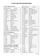
... Address 1 Input 3 A2 Slave Address 2 Input 4 GND GND 5 SDA Serial Data 6 SCL Serial Clock 7 WP Write Protect 8 VCC VCC IC1202 (LCD Drive / LCD Signal Process / TV Micro Controller) Pin No. Signal Name Function 1 V-OUT Video Signal Output 2 DEFECT-SW Defect Switching 3 VCC VCC 4 DET-OUT Video Detect Output 5 APC APC Filter...
... Address 1 Input 3 A2 Slave Address 2 Input 4 GND GND 5 SDA Serial Data 6 SCL Serial Clock 7 WP Write Protect 8 VCC VCC IC1202 (LCD Drive / LCD Signal Process / TV Micro Controller) Pin No. Signal Name Function 1 V-OUT Video Signal Output 2 DEFECT-SW Defect Switching 3 VCC VCC 4 DET-OUT Video Detect Output 5 APC APC Filter...


