
Service Manual
Page 2
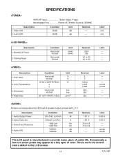
Number of useful life. Audio Output Power 2. Limit 0.8/0.8 3.0/3.0 ---->45/45 >45/45 The LCD panel is not to provide many years of Pixels 2. Limit >43 >45 Description 1. Over Scan 2. Resolution 4. Response 4. Limit --------- ...
Number of useful life. Audio Output Power 2. Limit 0.8/0.8 3.0/3.0 ---->45/45 >45/45 The LCD panel is not to provide many years of Pixels 2. Limit >43 >45 Description 1. Over Scan 2. Resolution 4. Response 4. Limit --------- ...

Service Manual
Page 4
... or child might alter the safety characteristics of this chassis to protect both the technician and the customer. Leakage Current Hot Check - Reverse the instrument power cord plug in the on the Liquid Crystal Panel. 3. b. READING SHOULD NOT BE ABOVE 0.5 mA DEVICE BEING TESTED LEAKAGE CURRENT TESTER +_ TEST ALL EXPOSED METAL...
... or child might alter the safety characteristics of this chassis to protect both the technician and the customer. Leakage Current Hot Check - Reverse the instrument power cord plug in the on the Liquid Crystal Panel. 3. b. READING SHOULD NOT BE ABOVE 0.5 mA DEVICE BEING TESTED LEAKAGE CURRENT TESTER +_ TEST ALL EXPOSED METAL...

Service Manual
Page 5
... protection they comply with components, parts, or wiring that leads and components do not touch thermally hot parts,c. near thermally hot parts-be sold. near sharp edges,b. Product Safety Notice - The product's safety is being serviced. 2-2 LCVISP Observe original lead dress. Some electrical and mechanical parts have the same safety characteristics..., take corrective action to confirm they give necessarily be replaced with the recognized product safety and electrical codes of place, or frayed wiring. 4. Check AC power cord for damage. 5.
... protection they comply with components, parts, or wiring that leads and components do not touch thermally hot parts,c. near thermally hot parts-be sold. near sharp edges,b. Product Safety Notice - The product's safety is being serviced. 2-2 LCVISP Observe original lead dress. Some electrical and mechanical parts have the same safety characteristics..., take corrective action to confirm they give necessarily be replaced with the recognized product safety and electrical codes of place, or frayed wiring. 4. Check AC power cord for damage. 5.

Service Manual
Page 6
...10W 0.15 F TEST PROBE TO EXPOSED METAL PARTS CONNECT TO KNOWN EARTH GROUND SAFETY NOTICE Many electrical and mechanical parts in this manual; Disconnect AC power before returning the monitor to the user, perform the following manner. • Plug the AC cord directly into a 120 volt AC outlet, and... connect the DC power cable into the receiver's DC jack. (Do not use of a substitute replacement parts which follow: WARNING 1. peak AC.) or more is not lodged...
...10W 0.15 F TEST PROBE TO EXPOSED METAL PARTS CONNECT TO KNOWN EARTH GROUND SAFETY NOTICE Many electrical and mechanical parts in this manual; Disconnect AC power before returning the monitor to the user, perform the following manner. • Plug the AC cord directly into a 120 volt AC outlet, and... connect the DC power cable into the receiver's DC jack. (Do not use of a substitute replacement parts which follow: WARNING 1. peak AC.) or more is not lodged...

Service Manual
Page 8
... and off or the maximum heat-resistance temperature of the soldering bit, it . When the tip of the soldering bit may be peeled off the power of it is higher than the conventional lead solder by 40°C, we recommend you to use a dedicated soldering bit, if you are indicated as...
... and off or the maximum heat-resistance temperature of the soldering bit, it . When the tip of the soldering bit may be peeled off the power of it is higher than the conventional lead solder by 40°C, we recommend you to use a dedicated soldering bit, if you are indicated as...

Service Manual
Page 16
... ADJUSTMENT INSTRUCTIONS NOTE: CBA AND PWB MEANS PRINTED WIRING BOARD." Color Analyzer How to change data value. o / p] to enter the service mode: Press [MENU] and [POWER] buttons on the table to perform these adjustments unless the proper equipment is important to access next item. Initial Setting General : Enter service mode. Test...
... ADJUSTMENT INSTRUCTIONS NOTE: CBA AND PWB MEANS PRINTED WIRING BOARD." Color Analyzer How to change data value. o / p] to enter the service mode: Press [MENU] and [POWER] buttons on the table to perform these adjustments unless the proper equipment is important to access next item. Initial Setting General : Enter service mode. Test...

Service Manual
Page 17
... adjustment. Initial Setting." [INPUT2]----(APL 20%) Press [3] button to select "C-DB(C/D2)" for Blue adjustment. Operate the unit for pure white. Turn the power off and on again. (Main power button on the LCDPanel surface after zero point calibration as a preparation. 2. See below Figure White A position B position Black C position 1. The following adjustment...
... adjustment. Initial Setting." [INPUT2]----(APL 20%) Press [3] button to select "C-DB(C/D2)" for Blue adjustment. Operate the unit for pure white. Turn the power off and on again. (Main power button on the LCDPanel surface after zero point calibration as a preparation. 2. See below Figure White A position B position Black C position 1. The following adjustment...
Service Manual
Page 18
If "C" position was beginning to be highly brightness, then adjust IIC-BUS dada. [RF/INPUT1]: BRT [INPUT2]: D1-BRT 7. Make sure that contrast and brightness controls are set to adjust. 6. [INPUT2] Press [MENU] button on the remote control unit and press [3] on the TV unit.) 5-3 A7121EA Confirm "C" position was beginning to bright, no need to initial position. 4. Turn the power off and on again. (Main power button on the remote control unit. (selecting "D1BRT" mode). 3. If "C" position is not available or to bright. 5.
If "C" position was beginning to be highly brightness, then adjust IIC-BUS dada. [RF/INPUT1]: BRT [INPUT2]: D1-BRT 7. Make sure that contrast and brightness controls are set to adjust. 6. [INPUT2] Press [MENU] button on the remote control unit and press [3] on the TV unit.) 5-3 A7121EA Confirm "C" position was beginning to bright, no need to initial position. 4. Turn the power off and on again. (Main power button on the remote control unit. (selecting "D1BRT" mode). 3. If "C" position is not available or to bright. 5.

Service Manual
Page 19
HOW TO INITIALIZE THE LCD TELEVISION 1. To enter the service mode, press [MENU] and [POWER] buttons on the upper right of the screen. 6-1 A7121INT Confirm "FF" indication on the TV unit simultaneously in the standby mode. 2. To initialize the LCD television, press [DISPLAY] button on the remote control unit. 3.
HOW TO INITIALIZE THE LCD TELEVISION 1. To enter the service mode, press [MENU] and [POWER] buttons on the upper right of the screen. 6-1 A7121INT Confirm "FF" indication on the TV unit simultaneously in the standby mode. 2. To initialize the LCD television, press [DISPLAY] button on the remote control unit. 3.

Service Manual
Page 20
... output voltage fluctuates. 7-2 4 When buzz sound can be heard in the vicinity of Contents for the Troubleshooting Flow Charts Flow Chart No. TROUBLESHOOTING Table of power circuit. 7-2 5 +35V is not output. 7-2 6 VT+33V is not output. 7-3 7 INV+22V is not output. 7-3 8 DTV-ON+3.3V is not output. 7-3 9 DTV-ON+2.5V is...
... output voltage fluctuates. 7-2 4 When buzz sound can be heard in the vicinity of Contents for the Troubleshooting Flow Charts Flow Chart No. TROUBLESHOOTING Table of power circuit. 7-2 5 +35V is not output. 7-2 6 VT+33V is not output. 7-3 7 INV+22V is not output. 7-3 8 DTV-ON+3.3V is not output. 7-3 9 DTV-ON+2.5V is...

Service Manual
Page 21
...D933 and their periphery circuit, and service it if defective. Is approximately 35V voltage supplied to the cathode of power circuit. Yes Is normal state restored when once unplugged No power cord is any leak or short-circuit on the loaded circuit, and service it if defective. (Q601,Q603,T601... Is the fuse (F601) normal? Yes Is the AL +12V line voltage normal? FLOW CHART NO.2 The fuse blows out. POWER SUPPLY SECTION FLOW CHART NO.1 The power cannot be heard in each rectifying circuit of the secondary side, and service it if defective. (IC901,IC904,IC905,IC906,D901,D902...
...D933 and their periphery circuit, and service it if defective. Is approximately 35V voltage supplied to the cathode of power circuit. Yes Is normal state restored when once unplugged No power cord is any leak or short-circuit on the loaded circuit, and service it if defective. (Q601,Q603,T601... Is the fuse (F601) normal? Yes Is the AL +12V line voltage normal? FLOW CHART NO.2 The fuse blows out. POWER SUPPLY SECTION FLOW CHART NO.1 The power cannot be heard in each rectifying circuit of the secondary side, and service it if defective. (IC901,IC904,IC905,IC906,D901,D902...

Service Manual
Page 23
... Is approximately 6.6V voltage supplied to the cathode of Q905? Is approximately 3.3V voltage supplied to the Pin(3) of emitter on Q905 when turning the power on? No Check D903, C903 and their periphery circuit, and service it if defective. Yes Check Q901, D916 and their periphery circuit, and service it...
... Is approximately 6.6V voltage supplied to the cathode of Q905? Is approximately 3.3V voltage supplied to the Pin(3) of emitter on Q905 when turning the power on? No Check D903, C903 and their periphery circuit, and service it if defective. Yes Check Q901, D916 and their periphery circuit, and service it...

Service Manual
Page 24
... Replace Q923. No Check D902, C902 and their periphery circuit, and service it if defective. Is approximately 12V voltage supplied to the cathode of D902? power on? FLOW CHART NO.18 DTV-ON+1.8V is not output. Is approximately 6.8V voltage supplied to the Yes Check Q918, D940 and their periphery...
... Replace Q923. No Check D902, C902 and their periphery circuit, and service it if defective. Is approximately 12V voltage supplied to the cathode of D902? power on? FLOW CHART NO.18 DTV-ON+1.8V is not output. Is approximately 6.8V voltage supplied to the Yes Check Q918, D940 and their periphery...

Service Manual
Page 29
...-1 CL1107 1 2 KEY SWITCH KEY SWITCH FUNCTION CBA CN1302 3 REMOTE 4 P-ON-H CL1104 3 4 RV1142 REMOTE SENSOR Q1142 LED DRIVE D1142 POWER AL+3.3V(D) IR SENSOR CBA DTV-ON-H BACKLIGHT-SW P-ON-H BACKLIGHT-ADJ TO POWER SUPPLY BLOCK DIAGRAM TO LCD BACKLIGHT BLOCK DIAGRAM IF-MUTE INPUT-2 INPUT-0 INPUT-1 S-SW AFT-IN FSC TO IF...
...-1 CL1107 1 2 KEY SWITCH KEY SWITCH FUNCTION CBA CN1302 3 REMOTE 4 P-ON-H CL1104 3 4 RV1142 REMOTE SENSOR Q1142 LED DRIVE D1142 POWER AL+3.3V(D) IR SENSOR CBA DTV-ON-H BACKLIGHT-SW P-ON-H BACKLIGHT-ADJ TO POWER SUPPLY BLOCK DIAGRAM TO LCD BACKLIGHT BLOCK DIAGRAM IF-MUTE INPUT-2 INPUT-0 INPUT-1 S-SW AFT-IN FSC TO IF...

Service Manual
Page 34
...REG. IC901 +1.2V REG. Q901 SW+3.3V AL+1.2V(D) AL+3.3V(D) AL+3.3V(A) IC905 +5V REG. Otherwise it may cause some components in the power supply circuit are not defective before you connect the AC plug to fail. 4A/125V CAUTION ! : For continued protection against risk of fire, replace only... with same type 4 A, 125V fuse. BE CAREFUL. 4A/125V F601 4A/125V L601 LINE FILTER HOT D605 - Fixed voltage (or Auto voltage selectable) power supply circuit is measured using hot GND as a common terminal. 8-6 AC601 AC CORD HOT CIRCUIT. If Main Fuse (F601) is blown , check to see that...
...REG. IC901 +1.2V REG. Q901 SW+3.3V AL+1.2V(D) AL+3.3V(D) AL+3.3V(A) IC905 +5V REG. Otherwise it may cause some components in the power supply circuit are not defective before you connect the AC plug to fail. 4A/125V CAUTION ! : For continued protection against risk of fire, replace only... with same type 4 A, 125V fuse. BE CAREFUL. 4A/125V F601 4A/125V L601 LINE FILTER HOT D605 - Fixed voltage (or Auto voltage selectable) power supply circuit is measured using hot GND as a common terminal. 8-6 AC601 AC CORD HOT CIRCUIT. If Main Fuse (F601) is blown , check to see that...

Service Manual
Page 35
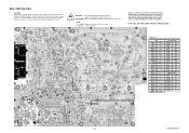
Q424 SWITCHING Q421 CURRENT CONTROL SWITCH T401 3 9 6 10 1 4 5 8 2 7 CN401 1 2 Q422 OVER VOLTAGE PROTECTOR BACK LIGHT 8-7 Q464 SWITCHING Q461 CURRENT CONTROL SWITCH Q425 OVER CURERENT PROTECTOR T403 3 9 6 10 1 4 5 8 2 7 Q462 OVER VOLTAGE PROTECTOR CN403 1 2 BACK LIGHT LCD MODULE A7121BLLB MAIN CBA TO POWER SUPPLY BLOCK DIAGRAM INV+22V Q401 SW+22V Q407 SWITCHING TO SYSTEM CONTROL BLOCK DIAGRAM BACKLIGHT-ADJ Q405 SWITCHING Q404 OVER VOLTAGE PROTECTOR Q406 +10V REG. LCD Backlight Block Diagram NOTE: CBA AND PWB MEANS PRINTED WIRING BOARD.
Q424 SWITCHING Q421 CURRENT CONTROL SWITCH T401 3 9 6 10 1 4 5 8 2 7 CN401 1 2 Q422 OVER VOLTAGE PROTECTOR BACK LIGHT 8-7 Q464 SWITCHING Q461 CURRENT CONTROL SWITCH Q425 OVER CURERENT PROTECTOR T403 3 9 6 10 1 4 5 8 2 7 Q462 OVER VOLTAGE PROTECTOR CN403 1 2 BACK LIGHT LCD MODULE A7121BLLB MAIN CBA TO POWER SUPPLY BLOCK DIAGRAM INV+22V Q401 SW+22V Q407 SWITCHING TO SYSTEM CONTROL BLOCK DIAGRAM BACKLIGHT-ADJ Q405 SWITCHING Q404 OVER VOLTAGE PROTECTOR Q406 +10V REG. LCD Backlight Block Diagram NOTE: CBA AND PWB MEANS PRINTED WIRING BOARD.

Service Manual
Page 37
...: Fixed Voltage (or Auto voltage selectable) power supply circuit is blown, first check to the AC power supply. If Main Fuse (F601) is used in the power supply circuit are as shown below: Plug the TV power cord into a standard AC outlet.: Voltage 1 2 5.0 3 5.0 Power on the drawings for ordering. Voltage indications ...on foil side. : Used to indicate a test point with no test pin. : Used to indicate a test point with their part numbers in the power supply circuit to the line number 1-D3 "1" of the area "B1". LIST OF CAUTION, NOTES, AND SYMBOLS USED IN THE SCHEMATIC DIAGRAMS ON THE ...
...: Fixed Voltage (or Auto voltage selectable) power supply circuit is blown, first check to the AC power supply. If Main Fuse (F601) is used in the power supply circuit are as shown below: Plug the TV power cord into a standard AC outlet.: Voltage 1 2 5.0 3 5.0 Power on the drawings for ordering. Voltage indications ...on foil side. : Used to indicate a test point with no test pin. : Used to indicate a test point with their part numbers in the power supply circuit to the line number 1-D3 "1" of the area "B1". LIST OF CAUTION, NOTES, AND SYMBOLS USED IN THE SCHEMATIC DIAGRAMS ON THE ...

Service Manual
Page 42
...in this unit. If Main Fuse (F601) is blown , check to see that all components in hot circuit is used in the power supply circuit to the AC power supply. NOTE: CBA AND PWB MEANS PRINTED WIRING BOARD. 4A/125V CAUTION ! : For continued protection against risk of fire, replace ...only with same type 4 A, 125V fuse. NOTE: The voltage for parts in the power supply circuit are not defective before you connect the AC plug to fail. MAIN 5/5 Ref No. ATTENTION : Utiliser un fusible de rechange de même...
...in this unit. If Main Fuse (F601) is blown , check to see that all components in hot circuit is used in the power supply circuit to the AC power supply. NOTE: CBA AND PWB MEANS PRINTED WIRING BOARD. 4A/125V CAUTION ! : For continued protection against risk of fire, replace ...only with same type 4 A, 125V fuse. NOTE: The voltage for parts in the power supply circuit are not defective before you connect the AC plug to fail. MAIN 5/5 Ref No. ATTENTION : Utiliser un fusible de rechange de même...
Service Manual
Page 48
... CONNECTORS CN61 A-4 CN62 B-4 CN401 F-1 CN403 F-3 CN1201 B-1 CN1202 C-1 CN1204 A-3 CN1301 E-1 CN1302 F-5 CN1303 E-1 9-13 BA7120F01011-1 Fixed voltage (or Auto voltage selectable) power supply circuit is required. NOTE: The voltage for parts in hot circuit is blown , check to see that all components in order to have the... ability to increase the input slowly,when troubleshooting this unit. Also, in the power supply circuit are not defective before you connect the AC plug to fail. 4A/125V CAUTION ! : For continued protection...
... CONNECTORS CN61 A-4 CN62 B-4 CN401 F-1 CN403 F-3 CN1201 B-1 CN1202 C-1 CN1204 A-3 CN1301 E-1 CN1302 F-5 CN1303 E-1 9-13 BA7120F01011-1 Fixed voltage (or Auto voltage selectable) power supply circuit is required. NOTE: The voltage for parts in hot circuit is blown , check to see that all components in order to have the... ability to increase the input slowly,when troubleshooting this unit. Also, in the power supply circuit are not defective before you connect the AC plug to fail. 4A/125V CAUTION ! : For continued protection...

Service Manual
Page 49
... IC1202 WF7 PIN 14 OF IC801 9-14 BA7120F01011-1 NOTE: CBA AND PWB MEANS PRINTED WIRING BOARD. Fixed voltage (or Auto voltage selectable) power supply circuit is required. NOTE: The voltage for parts in hot circuit is blown , check to see that all components in order to ... Bottom View CAUTION ! Because a hot chassis ground is present in the power supply circuit, an isolation transformer must be used in the power supply circuit to the AC power supply. Otherwise it may cause some components in this type power supply circuit, a variable isolation transformer is used . If Main Fuse ...
... IC1202 WF7 PIN 14 OF IC801 9-14 BA7120F01011-1 NOTE: CBA AND PWB MEANS PRINTED WIRING BOARD. Fixed voltage (or Auto voltage selectable) power supply circuit is required. NOTE: The voltage for parts in hot circuit is blown , check to see that all components in order to ... Bottom View CAUTION ! Because a hot chassis ground is present in the power supply circuit, an isolation transformer must be used in the power supply circuit to the AC power supply. Otherwise it may cause some components in this type power supply circuit, a variable isolation transformer is used . If Main Fuse ...


