

Service Manual
Page 1
SERVICE MANUAL LCD COLOR TV LC-15AV7U SERVICE MANUAL S17F1LC15AV7U LCD COLOR TV MODEL LC-15AV7U In the interests of user-safety (Required by safety regulations in some countries) the set ... service only. 1 The contents are subject to be used . MODEL LC-15AV7U CONTENTS Page SPECIFICATIONS ...1-1 IMPORTANT SAFEGUARDS AND PRECAUTIONS 2-1 STANDARD NOTES FOR SERVICING 3-1 CABINET DISASSEMBLY INSTRUCTIONS 4-1 ELECTRICAL ADJUSTMENT INSTRUCTIONS 5-1 HOW TO INITIALIZE THE LCD TELEVISION 6-1 TROUBLESHOOTING ...7-1 BLOCK DIAGRAMS ...8-1 SCHEMATIC DIAGRAMS/ CBA'S AND TEST POINTS 9-1 WAVEFORMS...
SERVICE MANUAL LCD COLOR TV LC-15AV7U SERVICE MANUAL S17F1LC15AV7U LCD COLOR TV MODEL LC-15AV7U In the interests of user-safety (Required by safety regulations in some countries) the set ... service only. 1 The contents are subject to be used . MODEL LC-15AV7U CONTENTS Page SPECIFICATIONS ...1-1 IMPORTANT SAFEGUARDS AND PRECAUTIONS 2-1 STANDARD NOTES FOR SERVICING 3-1 CABINET DISASSEMBLY INSTRUCTIONS 4-1 ELECTRICAL ADJUSTMENT INSTRUCTIONS 5-1 HOW TO INITIALIZE THE LCD TELEVISION 6-1 TROUBLESHOOTING ...7-1 BLOCK DIAGRAMS ...8-1 SCHEMATIC DIAGRAMS/ CBA'S AND TEST POINTS 9-1 WAVEFORMS...

Service Manual
Page 20
TROUBLESHOOTING Table of power circuit. 7-2 5 +35V is not output. 7-2 6 VT+33V is not output. 7-3 7 INV+22V is not output. 7-3 8 DTV-ON+3.3V is not output. 7-3 9 DTV-... be turned on. 7-2 2 The fuse blows out. 7-2 3 When the output voltage fluctuates. 7-2 4 When buzz sound can be heard in the vicinity of Contents for the Troubleshooting Flow Charts Flow Chart No.
TROUBLESHOOTING Table of power circuit. 7-2 5 +35V is not output. 7-2 6 VT+33V is not output. 7-3 7 INV+22V is not output. 7-3 8 DTV-ON+3.3V is not output. 7-3 9 DTV-... be turned on. 7-2 2 The fuse blows out. 7-2 3 When the output voltage fluctuates. 7-2 4 When buzz sound can be heard in the vicinity of Contents for the Troubleshooting Flow Charts Flow Chart No.
Service Manual
Page 48
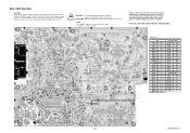
...) is present in the power supply circuit, an isolation transformer must be used in order to have the ability to increase the input slowly,when troubleshooting this unit. Position ICS IC31 B-3 IC61 A-3 IC601 D-5 IC801 C-5 IC851 C-2 IC852 B-3 IC901 E-1 IC904 D-3 IC905 E-3 IC906 D-2 IC1202 B-2 IC1205 E-1 TRANSISTORS Q401 E-3 Q402 E-2 Q403 F-1 Q404 F-1 Q405 F-1 Q406 F-1 Q407 F-1 Q421...
...) is present in the power supply circuit, an isolation transformer must be used in order to have the ability to increase the input slowly,when troubleshooting this unit. Position ICS IC31 B-3 IC61 A-3 IC601 D-5 IC801 C-5 IC851 C-2 IC852 B-3 IC901 E-1 IC904 D-3 IC905 E-3 IC906 D-2 IC1202 B-2 IC1205 E-1 TRANSISTORS Q401 E-3 Q402 E-2 Q403 F-1 Q404 F-1 Q405 F-1 Q406 F-1 Q407 F-1 Q421...

Service Manual
Page 49
... is present in hot circuit is blown , check to see that all components in order to have the ability to increase the input slowly,when troubleshooting this unit. ATTENTION : Utiliser un fusible de rechange de même type de 4A, 125V. NOTE: The voltage for parts in the power supply circuit...
... is present in hot circuit is blown , check to see that all components in order to have the ability to increase the input slowly,when troubleshooting this unit. ATTENTION : Utiliser un fusible de rechange de même type de 4A, 125V. NOTE: The voltage for parts in the power supply circuit...


