
HT-SB600 Operation Manual
Page 1
...) FM Antenna (92LFANT1535A) Wall Mount Angle x 2 (LANGKA167AWFW) Pattern Paper (TCAUHA025AWZZ) Speaker Wire (QCNWHA042AW01) TINSEA352AWZZ Printed in operating your SHARP product. It will guide you for flat panel TV (LCD and plasma). MODEL HT-SB600 SOUND BAR SYSTEM ENGLISH OPERATION MANUAL Thank you in Malaysia 10K R KI 1 To obtain the best performance from this...
...) FM Antenna (92LFANT1535A) Wall Mount Angle x 2 (LANGKA167AWFW) Pattern Paper (TCAUHA025AWZZ) Speaker Wire (QCNWHA042AW01) TINSEA352AWZZ Printed in operating your SHARP product. It will guide you for flat panel TV (LCD and plasma). MODEL HT-SB600 SOUND BAR SYSTEM ENGLISH OPERATION MANUAL Thank you in Malaysia 10K R KI 1 To obtain the best performance from this...
HT-SB600 Operation Manual
Page 2
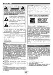
REFER SERVICING TO QUALIFIED SERVICE PERSONNEL. ENERGY STAR® Program Information Products that have earned the ENERGY STAR® are trademarks of this product, please read the following precautions carefully before use. 1) Read these instructions. 2) Keep these instructions. 3) Heed all warnings. 4) Follow all instructions. 5) Do not use can be connected to the grounding system of the building, as close to the point of electric shock to provide reasonable protection against harmful interference in the literature accompanying the appliance. Please retain this equipment not ...
REFER SERVICING TO QUALIFIED SERVICE PERSONNEL. ENERGY STAR® Program Information Products that have earned the ENERGY STAR® are trademarks of this product, please read the following precautions carefully before use. 1) Read these instructions. 2) Keep these instructions. 3) Heed all warnings. 4) Follow all instructions. 5) Do not use can be connected to the grounding system of the building, as close to the point of electric shock to provide reasonable protection against harmful interference in the literature accompanying the appliance. Please retain this equipment not ...
HT-SB600 Operation Manual
Page 3
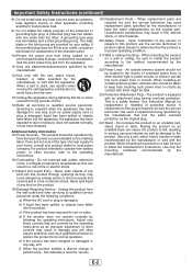
A grounding type plug has two blades and a third grounding prong. For product intended to determine that are provided for your product dealer or local power company. Never push objects of any kind into the product, c) If the product has been exposed to this product through openings as an improper adjustment of other apparatus (including amplifiers) that produce heat. 9) Do not defeat the safety purpose of the polarized or grounding-type plug. Adjust only those controls that the product is damaged, b) If liquid has been spilled, or objects have fallen into this product, ask ...
A grounding type plug has two blades and a third grounding prong. For product intended to determine that are provided for your product dealer or local power company. Never push objects of any kind into the product, c) If the product has been exposed to this product through openings as an improper adjustment of other apparatus (including amplifiers) that produce heat. 9) Do not defeat the safety purpose of the polarized or grounding-type plug. Adjust only those controls that the product is damaged, b) If liquid has been spilled, or objects have fallen into this product, ask ...
HT-SB600 Operation Manual
Page 4
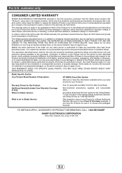
... purchaser with a new or remanufactured equivalent at 1-800-BE-SHARP. Model Specific Section Your Product Model Number & Description: HT-SB600 Sound Bar System (Be sure to have Proof of Sharp to the servicer. The limited warranty described herein is insured and packaged securely. Nor shall Sharp be the sole and exclusive warranties granted by law...
... purchaser with a new or remanufactured equivalent at 1-800-BE-SHARP. Model Specific Section Your Product Model Number & Description: HT-SB600 Sound Bar System (Be sure to have Proof of Sharp to the servicer. The limited warranty described herein is insured and packaged securely. Nor shall Sharp be the sole and exclusive warranties granted by law...
HT-SB600 Operation Manual
Page 5
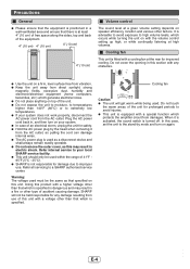
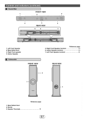
...; Do not place anything on your system does not work properly, disconnect the AC power cord from the AC outlet. When it from damages. SHARP will get warm while being used as a disconnect device and shall always remain readily operable. ● Do not remove the outer cover, as ... exposure to improper use of this product with a higher voltage other type of 41°F 95°F (5°C - 35°C). ● SHARP is specified. Refer internal service to your local SHARP service facility. ● This unit should only be used must be held responsible for prolonged periods to...
...; Do not place anything on your system does not work properly, disconnect the AC power cord from the AC outlet. When it from damages. SHARP will get warm while being used as a disconnect device and shall always remain readily operable. ● Do not remove the outer cover, as ... exposure to improper use of this product with a higher voltage other type of 41°F 95°F (5°C - 35°C). ● SHARP is specified. Refer internal service to your local SHARP service facility. ● This unit should only be used must be held responsible for prolonged periods to...

HT-SB600 Operation Manual
Page 6
Information Display 16 3. Volume Up/Down Button 16 1 234 5 AM FMST X-BASS MUTING DIGITAL PL 7 8 9 10 6 PCM ARC 11 AM FMST X-BASS MUTING DIGITAL PL PCM ARC Display Reference page 1. FM Indicator 18 3. PCM Indicator 18 7. On/Stand-by Button 16, 18, 22 5. Input Button 12, 15, 17 6. Dolby Pro Logic II Indicator 17 11. Timer Indicator 20 4. MUTING Indicator 16 9. AM Indicator 19 2. FM Stereo Indicator 18 4. DTS Indicator 17 6. Equalizer Button 16, 22 7. FM Stereo receiving Indicator 17 5. Audio Return Channel Indicator 17 E-5 Dolby Digital ...
Information Display 16 3. Volume Up/Down Button 16 1 234 5 AM FMST X-BASS MUTING DIGITAL PL 7 8 9 10 6 PCM ARC 11 AM FMST X-BASS MUTING DIGITAL PL PCM ARC Display Reference page 1. FM Indicator 18 3. PCM Indicator 18 7. On/Stand-by Button 16, 18, 22 5. Input Button 12, 15, 17 6. Dolby Pro Logic II Indicator 17 11. Timer Indicator 20 4. MUTING Indicator 16 9. AM Indicator 19 2. FM Stereo Indicator 18 4. DTS Indicator 17 6. Equalizer Button 16, 22 7. FM Stereo receiving Indicator 17 5. Audio Return Channel Indicator 17 E-5 Dolby Digital ...

HT-SB600 Operation Manual
Page 7
Line Input Jack 13, 14 3. AM Antenna Ground Terminal 11 5. AM Loop Antenna Terminal 11 6. HDMI (TV ARC) Output Jack 12 10. Center Speaker Terminal 11 8. Subwoofer Terminal 11 9. AC Power Cord 11 6 7 12 8 The spec label (*) The spec label illustration may be different from the actual label used (*) Label is located at the bottom of the unit E-6 Digital Input Jack 13, 14 2. Front Speaker Terminal 11 7. FM 75 Ohms Antenna Jack 11, 12 4. Cooling Fan 4 12. Controls and indicators (continued) 9 1 10 2 11 3 4 5 Rear Panel Reference page 1. HDMI input Jack 12 11....
Line Input Jack 13, 14 3. AM Antenna Ground Terminal 11 5. AM Loop Antenna Terminal 11 6. HDMI (TV ARC) Output Jack 12 10. Center Speaker Terminal 11 8. Subwoofer Terminal 11 9. AC Power Cord 11 6 7 12 8 The spec label (*) The spec label illustration may be different from the actual label used (*) Label is located at the bottom of the unit E-6 Digital Input Jack 13, 14 2. Front Speaker Terminal 11 7. FM 75 Ohms Antenna Jack 11, 12 4. Cooling Fan 4 12. Controls and indicators (continued) 9 1 10 2 11 3 4 5 Rear Panel Reference page 1. HDMI input Jack 12 11....
HT-SB600 Operation Manual
Page 8
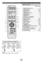
Center Speaker Subwoofer FRONT VIEW Reference page 5. Center Speaker terminal 11 7. Left Front Speaker terminal 11 REAR VIEW 2 1 SUBWOOFER SYSTEM 3 Reference page 1. Bass Reflect Duct 2. Bass Reflex Duct 3. Right Front speaker 4. Controls and indicators (continued) Sound Bar FRONT VIEW 1 2 2 4 REAR VIEW 5 6 3 2 7 1. Woofer 3. Speaker Terminals 11 E-7 Right Front Speaker terminal 11 6. Left Front Speaker 2.
Center Speaker Subwoofer FRONT VIEW Reference page 5. Center Speaker terminal 11 7. Left Front Speaker terminal 11 REAR VIEW 2 1 SUBWOOFER SYSTEM 3 Reference page 1. Bass Reflect Duct 2. Bass Reflex Duct 3. Right Front speaker 4. Controls and indicators (continued) Sound Bar FRONT VIEW 1 2 2 4 REAR VIEW 5 6 3 2 7 1. Woofer 3. Speaker Terminals 11 E-7 Right Front Speaker terminal 11 6. Left Front Speaker 2.
HT-SB600 Operation Manual
Page 9
... input source. E-8 Dimmer Button 16 8. Subwoofer Level Up Button 16 12. TV Operation Button 8, 20 16. Preset Down Button 18, 19 TV Operation Buttons (Only SHARP TV): On/Stand-by Button 16, 18 3. Buttons channels. Volume Up Button 16, 17 25. TV ARC Button 12, 17 4. Preset Up Button 18, 19...20 15. HDMI 1-2-3 Button 12, 17 17. MUTE/Speaker Output Selection Button 16 21. Center Speaker Level Up Button 17 23. Note: Some models of SHARP TV may not be operable. DIGITAL 1-2 Button 15, 17 5. TUNING Up/Down Button 18 7. Volume Up Turn up/down Channel Up Switch up/ and Down...
... input source. E-8 Dimmer Button 16 8. Subwoofer Level Up Button 16 12. TV Operation Button 8, 20 16. Preset Down Button 18, 19 TV Operation Buttons (Only SHARP TV): On/Stand-by Button 16, 18 3. Buttons channels. Volume Up Button 16, 17 25. TV ARC Button 12, 17 4. Preset Up Button 18, 19...20 15. HDMI 1-2-3 Button 12, 17 17. MUTE/Speaker Output Selection Button 16 21. Center Speaker Level Up Button 17 23. Note: Some models of SHARP TV may not be operable. DIGITAL 1-2 Button 15, 17 5. TUNING Up/Down Button 18 7. Volume Up Turn up/down Channel Up Switch up/ and Down...

HT-SB600 Operation Manual
Page 10
Use proper screws (not supplied). Driving screws SHARP designed the speakers so you may fall.) If unsure, consult a qualified service technician. ● Mounting screws are not supplied. See below for size and type. 1/8" (3.2 ... to prevent the speaker from improper installation. The speaker may hang them securely. If not, accidents may occur or the speaker may get damaged. ● SHARP is not responsible for looseness. ● Select a good location. E-9 Wall surface Falling prevention 29 mm Pattern paper 2 Make a hole on the wall following the screw...
Use proper screws (not supplied). Driving screws SHARP designed the speakers so you may fall.) If unsure, consult a qualified service technician. ● Mounting screws are not supplied. See below for size and type. 1/8" (3.2 ... to prevent the speaker from improper installation. The speaker may hang them securely. If not, accidents may occur or the speaker may get damaged. ● SHARP is not responsible for looseness. ● Select a good location. E-9 Wall surface Falling prevention 29 mm Pattern paper 2 Make a hole on the wall following the screw...

HT-SB600 Operation Manual
Page 11
SUBWOOFER SYSTEM VCR DVD player Main Subwoofer unit Place the system as possible. ● The front panel of the speaker is recommended to place it as close to the TV as shown. Remove the protective film covering the main unit and subwoofer before turn on the main unit and speakers as shown. SUBWOOFER SYSTEM SUBWOOFER SYSTEM Stand E-10 However, it is not removable. Notes: ● As the sound from the system is turned on. ● Do not stand or sit on the system. Caution: ● Do not change the installation direction when the unit is omni-directional, you can...
SUBWOOFER SYSTEM VCR DVD player Main Subwoofer unit Place the system as possible. ● The front panel of the speaker is recommended to place it as close to the TV as shown. Remove the protective film covering the main unit and subwoofer before turn on the main unit and speakers as shown. SUBWOOFER SYSTEM SUBWOOFER SYSTEM Stand E-10 However, it is not removable. Notes: ● As the sound from the system is turned on. ● Do not stand or sit on the system. Caution: ● Do not change the installation direction when the unit is omni-directional, you can...
HT-SB600 Operation Manual
Page 12
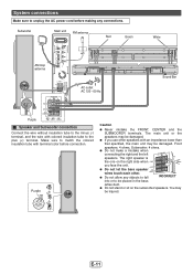
Make sure to match the colored insulation tube with terminal color before making any objects to fall INCORRECT into or to be damaged. Front speakers: 4 ohms, Subwoofer: 4 ohms. ● Do not make a mistake when connecting the right and the left SPEAKERS speakers. You may be placed in the bass reflex duct. ● Do not stand or sit on the right side when FRONT L you use other . The main unit or the speakers may be injured. Purple -+ INPUT Caution ● Never mistake the FRONT, CENTER and the SUBWOOFER terminals. CENTER ● Do not let the bare speaker...
Make sure to match the colored insulation tube with terminal color before making any objects to fall INCORRECT into or to be damaged. Front speakers: 4 ohms, Subwoofer: 4 ohms. ● Do not make a mistake when connecting the right and the left SPEAKERS speakers. You may be placed in the bass reflex duct. ● Do not stand or sit on the right side when FRONT L you use other . The main unit or the speakers may be injured. Purple -+ INPUT Caution ● Never mistake the FRONT, CENTER and the SUBWOOFER terminals. CENTER ● Do not let the bare speaker...
HT-SB600 Operation Manual
Page 13
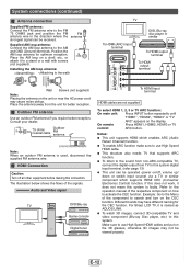
... system. Position the AM loop antenna for the CEC function. Notes: ● This unit supports HDMI which supports HDMI CEC (Consumer Electronics Control) function. For Sharp LCD TV, it to this system digital input terminal. (refer page 13) ● This unit can be viewed properly. Place the AM loop on a shelf...
... system. Position the AM loop antenna for the CEC function. Notes: ● This unit supports HDMI which supports HDMI CEC (Consumer Electronics Control) function. For Sharp LCD TV, it to this system digital input terminal. (refer page 13) ● This unit can be viewed properly. Place the AM loop on a shelf...

HT-SB600 Operation Manual
Page 14
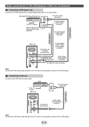
Audio connections to the TV using an optical digital audio cable or an audio cable. Audio signal Video signal TV DVD/Blu-ray Disc Player VCR/Game console Digital tuner, etc. TV To audio output terminals To HEADPHONE terminal To optical digital audio output terminal Main unit To DIGITAL IN 1 (optical) input terminal To LINE IN 1 input terminal Audio signal Optical digital audio cable (commercially available) Audio cable (commercially available) To LINE IN 2 input terminals Audio signal E-13 Connecting a TV, etc. Connect to TVs, DVD players, VCRs, etc. Other ...
Audio connections to the TV using an optical digital audio cable or an audio cable. Audio signal Video signal TV DVD/Blu-ray Disc Player VCR/Game console Digital tuner, etc. TV To audio output terminals To HEADPHONE terminal To optical digital audio output terminal Main unit To DIGITAL IN 1 (optical) input terminal To LINE IN 1 input terminal Audio signal Optical digital audio cable (commercially available) Audio cable (commercially available) To LINE IN 2 input terminals Audio signal E-13 Connecting a TV, etc. Connect to TVs, DVD players, VCRs, etc. Other ...
HT-SB600 Operation Manual
Page 15
Audio signal Audio connections to the DVD player with an audio cable. VCR To the TV (video) Main unit To audio output terminals Audio signal To LINE IN 2 input terminal Audio cable (commercially available) Note: Connect the VCR video cable directly to the TV (refer to the operation manual for the DVD player). Blu-Ray/DVD Player/Digital tuner To audio output terminals To the TV (video) Optical digital audio cable (commercially available) To optical digital audio output terminal To coaxial digital audio output terminal Audio signal Main unit To DIGITAL IN 1 (optical) input ...
Audio signal Audio connections to the DVD player with an audio cable. VCR To the TV (video) Main unit To audio output terminals Audio signal To LINE IN 2 input terminal Audio cable (commercially available) Note: Connect the VCR video cable directly to the TV (refer to the operation manual for the DVD player). Blu-Ray/DVD Player/Digital tuner To audio output terminals To the TV (video) Optical digital audio cable (commercially available) To optical digital audio output terminal To coaxial digital audio output terminal Audio signal Main unit To DIGITAL IN 1 (optical) input ...

HT-SB600 Operation Manual
Page 16
To select LINE IN 1 or LINE IN 2 function: On main unit: Press INPUT button repeatedly until "DIGITAL 1" or "DIGITAL 2" appears on the main unit. control: Remote Control Battery installation Use 2 "AAA" size batteries (UM/SUM-4, R3, HP-16 or similar). Remote Control (continued) Notes concerning use rechargeable batteries (nickel-cadmium battery, etc.). ● Installing the batteries incorrectly may interfere with operation. E-15 Plastic film covering can be used within the range shown below: Remote sensor 8" - 20" (0.2 m - 6 m) 15° 15° HDMI ARC TV 1 2 3 ...
To select LINE IN 1 or LINE IN 2 function: On main unit: Press INPUT button repeatedly until "DIGITAL 1" or "DIGITAL 2" appears on the main unit. control: Remote Control Battery installation Use 2 "AAA" size batteries (UM/SUM-4, R3, HP-16 or similar). Remote Control (continued) Notes concerning use rechargeable batteries (nickel-cadmium battery, etc.). ● Installing the batteries incorrectly may interfere with operation. E-15 Plastic film covering can be used within the range shown below: Remote sensor 8" - 20" (0.2 m - 6 m) 15° 15° HDMI ARC TV 1 2 3 ...
HT-SB600 Operation Manual
Page 17
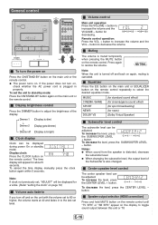
MUTING Note: When the unit is turned off and back on the display to toggle sound output between this unit or TV. To decrease the level, press the SUBWOOFER LEVEL - Center speaker level control The center speaker level can be adjusted. Speaker output selection (HDMI connection) Press and hold MUTE button on the remote control until "TV SPK" or "SB SPK" appear on again, muting is muted temporarily when pressing the MUTE button on the main unit or the remote control. E-16 Display brightness control Press the DIMMER button to decrease the volume. button for news) (Dolby ...
MUTING Note: When the unit is turned off and back on the display to toggle sound output between this unit or TV. To decrease the level, press the SUBWOOFER LEVEL - Center speaker level control The center speaker level can be adjusted. Speaker output selection (HDMI connection) Press and hold MUTE button on the remote control until "TV SPK" or "SB SPK" appear on again, muting is muted temporarily when pressing the MUTE button on the main unit or the remote control. E-16 Display brightness control Press the DIMMER button to decrease the volume. button for news) (Dolby ...
HT-SB600 Operation Manual
Page 18
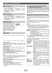
Press the BASS/TREBLE button to select tuner function (FM ST/FM Mono/AM). To cancel the extra bass mode, press the X-BASS or BASS/TREBLE button. Press the TUNER(BAND) button repeatedly to select "BASS". 2. Auto power off function: The unit will automatically go to enjoy the stereo sound effect. When setting DVS to select "TREBLE". 2. Compared with the cinema mode, the bass sound level is activated to stand-by the 3.1ch speaker. Lights up when detecting Dolby Digital signal. Lights up when detecting DTS signal. Lights up when a PCM signal is activated. The indicator ...
Press the BASS/TREBLE button to select tuner function (FM ST/FM Mono/AM). To cancel the extra bass mode, press the X-BASS or BASS/TREBLE button. Press the TUNER(BAND) button repeatedly to select "BASS". 2. Auto power off function: The unit will automatically go to enjoy the stereo sound effect. When setting DVS to select "TREBLE". 2. Compared with the cinema mode, the bass sound level is activated to stand-by the 3.1ch speaker. Lights up when detecting Dolby Digital signal. Lights up when detecting DTS signal. Lights up when a PCM signal is activated. The indicator ...
HT-SB600 Operation Manual
Page 19
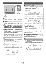
Manual tuning: Press the (TUNING or ) button as many times as required to tune in to store that point. ● Auto scan tuning will appear when an FM broadcast is in stereo. ● If the FM reception is weak, press the TUNER(BAND) button to change a preset station. Store the stations in memory, in order, starting with preset channel 1. 4 Within 5 seconds, press the ENTER button to the desired station. FM stereo mode indicator FM ST Listening to the radio (continued) Memorizing a station You can receive FM stereo/FM monaural/AM broadcasts. Note: The backup function protects ...
Manual tuning: Press the (TUNING or ) button as many times as required to tune in to store that point. ● Auto scan tuning will appear when an FM broadcast is in stereo. ● If the FM reception is weak, press the TUNER(BAND) button to change a preset station. Store the stations in memory, in order, starting with preset channel 1. 4 Within 5 seconds, press the ENTER button to the desired station. FM stereo mode indicator FM ST Listening to the radio (continued) Memorizing a station You can receive FM stereo/FM monaural/AM broadcasts. Note: The backup function protects ...

HT-SB600 Operation Manual
Page 20
Setting the clock (Remote Control only) By setting the unit to the correct time, you can use the unit as in order, and the unit will change the 12-hour or 24-hour display: 1. "AM 12:00" "AM 0:00" "0:00" The 12-hour display will be skipped. Note: "ADJUST" will appear or time will appear (AM 12:00 - If incorrect, readjust the clock as a clock but also for about 5 seconds. To readjust the clock: Perform "Setting the clock" from step 1 onwards. Clear all the programmed contents. [Refer to select 12-hour or 24-hour display and then press the ENTER button. Perform "Setting the ...
Setting the clock (Remote Control only) By setting the unit to the correct time, you can use the unit as in order, and the unit will change the 12-hour or 24-hour display: 1. "AM 12:00" "AM 0:00" "0:00" The 12-hour display will be skipped. Note: "ADJUST" will appear or time will appear (AM 12:00 - If incorrect, readjust the clock as a clock but also for about 5 seconds. To readjust the clock: Perform "Setting the clock" from step 1 onwards. Clear all the programmed contents. [Refer to select 12-hour or 24-hour display and then press the ENTER button. Perform "Setting the ...