
HT-SB600 Operation Manual
Page 1
...TREBLE MUTE SUBWOOFER LEVEL CENTER LEVEL PRESET VOL VOL PRESET TV INPUT CHANNEL VOL HT-SB600 Note: This product is recommended for purchasing this manual carefully. HT-SB600 Sound Bar system consisting of HT-SB600 (main unit), CP-SB600 (sound bar) and CP-SW600 (subwoofer). Accessories Please confirm that only ...x 4 (GITAUA004AW01) FM Antenna (92LFANT1535A) Wall Mount Angle x 2 (LANGKA167AWFW) Pattern Paper (TCAUHA025AWZZ) Speaker Wire (QCNWHA042AW01) TINSEA352AWZZ Printed in operating your SHARP product. To obtain the best performance from this product, please read this...
...TREBLE MUTE SUBWOOFER LEVEL CENTER LEVEL PRESET VOL VOL PRESET TV INPUT CHANNEL VOL HT-SB600 Note: This product is recommended for purchasing this manual carefully. HT-SB600 Sound Bar system consisting of HT-SB600 (main unit), CP-SB600 (sound bar) and CP-SW600 (subwoofer). Accessories Please confirm that only ...x 4 (GITAUA004AW01) FM Antenna (92LFANT1535A) Wall Mount Angle x 2 (LANGKA167AWFW) Pattern Paper (TCAUHA025AWZZ) Speaker Wire (QCNWHA042AW01) TINSEA352AWZZ Printed in operating your SHARP product. To obtain the best performance from this product, please read this...
HT-SB600 Operation Manual
Page 2
Model number Serial number Date of purchase Place of purchase NOTE This equipment has been tested and found to the presence of the following instructions when installing, operating and cleaning the product. However, there is intended to alert the user to comply with the manufacturer's instructions. WARNING FCC Regulations state that any ventilation openings. and worldwide patents issued & pending. In order to correct the interference by one or more of important operating and maintenance (servicing) instructions in the literature accompanying the ...
Model number Serial number Date of purchase Place of purchase NOTE This equipment has been tested and found to the presence of the following instructions when installing, operating and cleaning the product. However, there is intended to alert the user to comply with the manufacturer's instructions. WARNING FCC Regulations state that any ventilation openings. and worldwide patents issued & pending. In order to correct the interference by one or more of important operating and maintenance (servicing) instructions in the literature accompanying the ...
HT-SB600 Operation Manual
Page 3
Servicing is required when the apparatus has been damaged in any service or repairs to this product, ask the service technician to perform safety checks to determine that the product is damaged, liquid has been spilled or objects have fallen into the apparatus, the apparatus has been exposed to rain or moisture, does not operate normally, or has been dropped. Do not overload wall outlets, extension cords, or integral convenience receptacles as this product through openings as they exit from touching such power lines or circuits as power-supply cord or plug is in proper operating ...
Servicing is required when the apparatus has been damaged in any service or repairs to this product, ask the service technician to perform safety checks to determine that the product is damaged, liquid has been spilled or objects have fallen into the apparatus, the apparatus has been exposed to rain or moisture, does not operate normally, or has been dropped. Do not overload wall outlets, extension cords, or integral convenience receptacles as this product through openings as they exit from touching such power lines or circuits as power-supply cord or plug is in proper operating ...
HT-SB600 Operation Manual
Page 4
...workmanship and materials, and agrees that it is in addition to whatever implied warranties may not apply to a Sharp Authorized Servicer. Model Specific Section Your Product Model Number & Description: HT-SB600 Sound Bar System (Be sure to have Proof of the Product nor to the additional excluded item(s) set... forth below nor to any damages or defects in the Product which were caused by repairs or attempted repairs performed by Sharp and shall be granted...
...workmanship and materials, and agrees that it is in addition to whatever implied warranties may not apply to a Sharp Authorized Servicer. Model Specific Section Your Product Model Number & Description: HT-SB600 Sound Bar System (Be sure to have Proof of the Product nor to the additional excluded item(s) set... forth below nor to any damages or defects in the Product which were caused by repairs or attempted repairs performed by Sharp and shall be granted...
HT-SB600 Operation Manual
Page 5
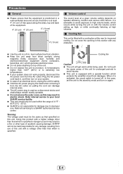
... in, and then turn on with the volume control setting up high, or while continually listening at high volumes. Refer all servicing to your local SHARP service facility. ● This unit should only be used . Warning: The voltage used as a disconnect device and shall always remain readily operable. ...● Do not remove the outer cover, as that specified on this unit. SHARP will get warm while being used within the range of 41°F 95°F (5°C - 35°C). ● SHARP is not responsible for any obstacles. ● Use the unit on a firm, level surface...
... in, and then turn on with the volume control setting up high, or while continually listening at high volumes. Refer all servicing to your local SHARP service facility. ● This unit should only be used . Warning: The voltage used as a disconnect device and shall always remain readily operable. ...● Do not remove the outer cover, as that specified on this unit. SHARP will get warm while being used within the range of 41°F 95°F (5°C - 35°C). ● SHARP is not responsible for any obstacles. ● Use the unit on a firm, level surface...

HT-SB600 Operation Manual
Page 6
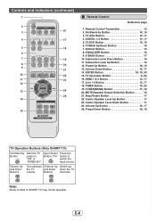
Remote Sensor 15 2. FM Indicator 18 3. FM Stereo receiving Indicator 17 5. On/Stand-by Button 16, 18, 22 5. AM Indicator 19 2. Dolby Pro Logic II Indicator 17 11. Timer Indicator 20 4. Equalizer Button 16, 22 7. Volume Up/Down Button 16 1 234 5 AM FMST X-BASS MUTING DIGITAL PL 7 8 9 10 6 PCM ARC 11 AM FMST X-BASS MUTING DIGITAL PL PCM ARC Display Reference page 1. Dolby Digital Indicator 17 10. PCM Indicator 18 7. Information Display 16 3. FM Stereo Indicator 18 4. DTS Indicator 17 6. X-BASS Indicator 17 8. Input Button 12, 15, 17 6. ...
Remote Sensor 15 2. FM Indicator 18 3. FM Stereo receiving Indicator 17 5. On/Stand-by Button 16, 18, 22 5. AM Indicator 19 2. Dolby Pro Logic II Indicator 17 11. Timer Indicator 20 4. Equalizer Button 16, 22 7. Volume Up/Down Button 16 1 234 5 AM FMST X-BASS MUTING DIGITAL PL 7 8 9 10 6 PCM ARC 11 AM FMST X-BASS MUTING DIGITAL PL PCM ARC Display Reference page 1. Dolby Digital Indicator 17 10. PCM Indicator 18 7. Information Display 16 3. FM Stereo Indicator 18 4. DTS Indicator 17 6. X-BASS Indicator 17 8. Input Button 12, 15, 17 6. ...

HT-SB600 Operation Manual
Page 7
HDMI input Jack 12 11. AM Antenna Ground Terminal 11 5. AM Loop Antenna Terminal 11 6. Center Speaker Terminal 11 8. Digital Input Jack 13, 14 2. AC Power Cord 11 6 7 12 8 The spec label (*) The spec label illustration may be different from the actual label used (*) Label is located at the bottom of the unit E-6 HDMI (TV ARC) Output Jack 12 10. Controls and indicators (continued) 9 1 10 2 11 3 4 5 Rear Panel Reference page 1. Cooling Fan 4 12. FM 75 Ohms Antenna Jack 11, 12 4. Subwoofer Terminal 11 9. Line Input Jack 13, 14 3. Front Speaker Terminal 11 7....
HDMI input Jack 12 11. AM Antenna Ground Terminal 11 5. AM Loop Antenna Terminal 11 6. Center Speaker Terminal 11 8. Digital Input Jack 13, 14 2. AC Power Cord 11 6 7 12 8 The spec label (*) The spec label illustration may be different from the actual label used (*) Label is located at the bottom of the unit E-6 HDMI (TV ARC) Output Jack 12 10. Controls and indicators (continued) 9 1 10 2 11 3 4 5 Rear Panel Reference page 1. Cooling Fan 4 12. FM 75 Ohms Antenna Jack 11, 12 4. Subwoofer Terminal 11 9. Line Input Jack 13, 14 3. Front Speaker Terminal 11 7....
HT-SB600 Operation Manual
Page 8
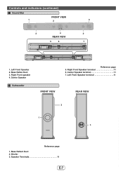
Center Speaker Subwoofer FRONT VIEW Reference page 5. Bass Reflect Duct 2. Center Speaker terminal 11 7. Controls and indicators (continued) Sound Bar FRONT VIEW 1 2 2 4 REAR VIEW 5 6 3 2 7 1. Bass Reflex Duct 3. Left Front Speaker 2. Left Front Speaker terminal 11 REAR VIEW 2 1 SUBWOOFER SYSTEM 3 Reference page 1. Right Front Speaker terminal 11 6. Woofer 3. Speaker Terminals 11 E-7 Right Front speaker 4.
Center Speaker Subwoofer FRONT VIEW Reference page 5. Bass Reflect Duct 2. Center Speaker terminal 11 7. Controls and indicators (continued) Sound Bar FRONT VIEW 1 2 2 4 REAR VIEW 5 6 3 2 7 1. Bass Reflex Duct 3. Left Front Speaker 2. Left Front Speaker terminal 11 REAR VIEW 2 1 SUBWOOFER SYSTEM 3 Reference page 1. Right Front Speaker terminal 11 6. Woofer 3. Speaker Terminals 11 E-7 Right Front speaker 4.
HT-SB600 Operation Manual
Page 9
... Operation Button 8, 20 16. TUNER(BAND) Button 17, 18 20. Preset Down Button 18, 19 TV Operation Buttons (Only SHARP TV): On/Stand-by Button 16, 18 3. Note: Some models of SHARP TV may not be operable. Line 1-2 Button 15, 17 18. MUTE/Speaker Output Selection Button 16 21. Center Speaker Level...
... Operation Button 8, 20 16. TUNER(BAND) Button 17, 18 20. Preset Down Button 18, 19 TV Operation Buttons (Only SHARP TV): On/Stand-by Button 16, 18 3. Note: Some models of SHARP TV may not be operable. Line 1-2 Button 15, 17 18. MUTE/Speaker Output Selection Button 16 21. Center Speaker Level...

HT-SB600 Operation Manual
Page 10
... the speakers so you may get damaged. ● SHARP is not responsible for accidents resulting from falling off the table. 3/8" (8-9 mm) Wall surface 3 Fix a wall mount plug (not supplied) into the hole using a hammer, ...
... the speakers so you may get damaged. ● SHARP is not responsible for accidents resulting from falling off the table. 3/8" (8-9 mm) Wall surface 3 Fix a wall mount plug (not supplied) into the hole using a hammer, ...

HT-SB600 Operation Manual
Page 11
Remove the protective film covering the main unit and subwoofer before turn on the main unit and speakers as shown. Caution: ● Do not change the installation direction when the unit is recommended to place it as close to the TV as shown. However, it is turned on. ● Do not stand or sit on the system. SUBWOOFER SYSTEM VCR DVD player Main Subwoofer unit Place the system as possible. ● The front panel of the speaker is omni-directional, you can place the speaker anywhere you may be injured. Placing the system Installation image: TV Placing the stand ...
Remove the protective film covering the main unit and subwoofer before turn on the main unit and speakers as shown. Caution: ● Do not change the installation direction when the unit is recommended to place it as close to the TV as shown. However, it is turned on. ● Do not stand or sit on the system. SUBWOOFER SYSTEM VCR DVD player Main Subwoofer unit Place the system as possible. ● The front panel of the speaker is omni-directional, you can place the speaker anywhere you may be injured. Placing the system Installation image: TV Placing the stand ...
HT-SB600 Operation Manual
Page 12
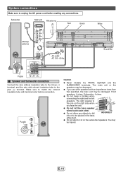
Make sure to match the colored insulation tube with an impedance lower than that specified, the main unit may be damaged. Purple -+ INPUT Caution ● Never mistake the FRONT, CENTER and the SUBWOOFER terminals. The right speaker is R the one on the subwoofer/speakers. The main unit or the speakers may be injured. You may be damaged. ● If you use other . CENTER ● Do not let the bare speaker wires touch each other speakers with terminal color before making any objects to fall INCORRECT into or to be placed in the bass reflex duct. ● Do...
Make sure to match the colored insulation tube with an impedance lower than that specified, the main unit may be damaged. Purple -+ INPUT Caution ● Never mistake the FRONT, CENTER and the SUBWOOFER terminals. The right speaker is R the one on the subwoofer/speakers. The main unit or the speakers may be injured. You may be damaged. ● If you use other . CENTER ● Do not let the bare speaker wires touch each other speakers with terminal color before making any objects to fall INCORRECT into or to be placed in the bass reflex duct. ● Do...
HT-SB600 Operation Manual
Page 13
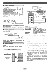
... or a wall with screws (not supplied). Consult your dealer. 75 ohms coaxial cable Outdoor FM antenna Note: When an outdoor FM antenna is faulty. For Sharp LCD TV, it to this system is used, disconnect the supplied FM antenna wire. Place the AM loop on /off all other equipment before making...
... or a wall with screws (not supplied). Consult your dealer. 75 ohms coaxial cable Outdoor FM antenna Note: When an outdoor FM antenna is faulty. For Sharp LCD TV, it to this system is used, disconnect the supplied FM antenna wire. Place the AM loop on /off all other equipment before making...

HT-SB600 Operation Manual
Page 14
Other connection (without HDMI) The illustration below shows the flows of the equipment to be connected. ● Fully insert the plugs to the TV using an optical digital audio cable or an audio cable. Connecting a TV, etc. TV To audio output terminals To HEADPHONE terminal To optical digital audio output terminal Main unit To DIGITAL IN 1 (optical) input terminal To LINE IN 1 input terminal Audio signal Optical digital audio cable (commercially available) Audio cable (commercially available) To LINE IN 2 input terminals Audio signal E-13 Notes: ● Refer to the operation manual...
Other connection (without HDMI) The illustration below shows the flows of the equipment to be connected. ● Fully insert the plugs to the TV using an optical digital audio cable or an audio cable. Connecting a TV, etc. TV To audio output terminals To HEADPHONE terminal To optical digital audio output terminal Main unit To DIGITAL IN 1 (optical) input terminal To LINE IN 1 input terminal Audio signal Optical digital audio cable (commercially available) Audio cable (commercially available) To LINE IN 2 input terminals Audio signal E-13 Notes: ● Refer to the operation manual...
HT-SB600 Operation Manual
Page 15
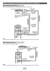
Blu-Ray/DVD Player/Digital tuner To audio output terminals To the TV (video) Optical digital audio cable (commercially available) To optical digital audio output terminal To coaxial digital audio output terminal Audio signal Main unit To DIGITAL IN 1 (optical) input terminal Coaxial digital audio cable (commercially available) To DIGITAL IN 2 (coaxial) terminal input Audio cable (commercially available) To LINE IN 2 input terminals Note: Connect the DVD video cable directly to the TV (refer to the operation manual for the DVD player). VCR To the TV (video) Main unit To audio ...
Blu-Ray/DVD Player/Digital tuner To audio output terminals To the TV (video) Optical digital audio cable (commercially available) To optical digital audio output terminal To coaxial digital audio output terminal Audio signal Main unit To DIGITAL IN 1 (optical) input terminal Coaxial digital audio cable (commercially available) To DIGITAL IN 2 (coaxial) terminal input Audio cable (commercially available) To LINE IN 2 input terminals Note: Connect the DVD video cable directly to the TV (refer to the operation manual for the DVD player). VCR To the TV (video) Main unit To audio ...

HT-SB600 Operation Manual
Page 16
On remote Press the "DIGITAL 1" or "DIGITAL 2" control: button. To select LINE IN 1 or LINE IN 2 function: On main unit: Press INPUT button repeatedly until "DIGITAL 1" or "DIGITAL 2" appears on the unit to strong light may cause the unit to malfunction. ● Batteries (battery pack or batteries installed) shall not be exposed to excessive heat such as sunshine, fire or the like. control: Remote Control Battery installation Use 2 "AAA" size batteries (UM/SUM-4, R3, HP-16 or similar). When inserting or removing the batteries, push them toward the battery terminals. 3 Close the ...
On remote Press the "DIGITAL 1" or "DIGITAL 2" control: button. To select LINE IN 1 or LINE IN 2 function: On main unit: Press INPUT button repeatedly until "DIGITAL 1" or "DIGITAL 2" appears on the unit to strong light may cause the unit to malfunction. ● Batteries (battery pack or batteries installed) shall not be exposed to excessive heat such as sunshine, fire or the like. control: Remote Control Battery installation Use 2 "AAA" size batteries (UM/SUM-4, R3, HP-16 or similar). When inserting or removing the batteries, push them toward the battery terminals. 3 Close the ...
HT-SB600 Operation Manual
Page 17
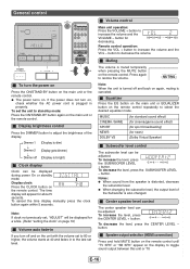
Volume control Main unit operation: Press the VOLUME + button to decrease the volume. button to increase the volume and the VOLUME - MUSIC CINEMA /GAME SPORT NEWS DOLBY VS (for standard sound effect) (for cinema/game sound effect) (for sport broadcasting) (for news) (Dolby Virtual Speaker) Subwoofer level control The subwoofer level can be adjusted. button. Center speaker level control The center speaker level can be displayed for a while. (Refer "setting the clock" on page 19) Volume auto fade-in If you turn off and on the main unit or the remote control. Muting...
Volume control Main unit operation: Press the VOLUME + button to decrease the volume. button to increase the volume and the VOLUME - MUSIC CINEMA /GAME SPORT NEWS DOLBY VS (for standard sound effect) (for cinema/game sound effect) (for sport broadcasting) (for news) (Dolby Virtual Speaker) Subwoofer level control The subwoofer level can be adjusted. button. Center speaker level control The center speaker level can be displayed for a while. (Refer "setting the clock" on page 19) Volume auto fade-in If you turn off and on the main unit or the remote control. Muting...
HT-SB600 Operation Manual
Page 18
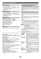
Press the BASS/TREBLE button to adjust the treble. Note: The backup function will protect the memorized function mode for theatrical use . This product incorporates decoders supporting the Dolby Digital system and DTS system. Within 5 seconds, press the VOLUME (+ or -) button to select "TREBLE". 2. On remote control: Press the LINE 1 or 2 button to select HDMI input. Press the HDMI 1 or 2 or 3 to select LINE IN 1 input or LINE IN 2 input. Audio Return Channel (ARC) (Audio Return Channel submenu) The audio return channel (ARC) function enables an HDMI ARC-...
Press the BASS/TREBLE button to adjust the treble. Note: The backup function will protect the memorized function mode for theatrical use . This product incorporates decoders supporting the Dolby Digital system and DTS system. Within 5 seconds, press the VOLUME (+ or -) button to select "TREBLE". 2. On remote control: Press the LINE 1 or 2 button to select HDMI input. Press the HDMI 1 or 2 or 3 to select LINE IN 1 input or LINE IN 2 input. Audio Return Channel (ARC) (Audio Return Channel submenu) The audio return channel (ARC) function enables an HDMI ARC-...
HT-SB600 Operation Manual
Page 19
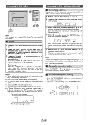
Tuning 1 Press the ON/STAND-BY button to turn the power on. 2 Press the INPUT button on the main unit or TUNER(BAND) button on the remote control repeatedly to select the desired frequency band (FM Stereo/FM Mono/AM). 3 Press the (TUNING or ) button to tune in stereo. ● If the FM reception is in to the desired station. Notes: ● When radio interference occurs, auto scan tuning may stop automatically at the push of a button. (Preset tuning) 1 Perform steps 1 - 3 in to the desired station. To receive an FM stereo transmission: ● " " will skip weak signal stations. &#...
Tuning 1 Press the ON/STAND-BY button to turn the power on. 2 Press the INPUT button on the main unit or TUNER(BAND) button on the remote control repeatedly to select the desired frequency band (FM Stereo/FM Mono/AM). 3 Press the (TUNING or ) button to tune in stereo. ● If the FM reception is in to the desired station. Notes: ● When radio interference occurs, auto scan tuning may stop automatically at the push of a button. (Preset tuning) 1 Perform steps 1 - 3 in to the desired station. To receive an FM stereo transmission: ● " " will skip weak signal stations. &#...

HT-SB600 Operation Manual
Page 20
If clock is restored after approx. 5 seconds. Note: "ADJUST" will appear or time will be displayed if the CLOCK button is pressed when the AC power supply is not set , you cannot use the timer function. 2. Perform "Setting the clock" from step 1. Before setting timer: 1. HDMI 1 HDMI 2 HDMI 3 TV ARC DIGITAL 1 TUNER LINE 2 LINE 1 DIGITAL 2 ● When you select the tuner, select a station by pressing the or button, and then press the ENTER button. ● If a station has not been programmed, "NOPRESET" will enter the timer stand-by 1 hour. Settings are not displayed). &#...
If clock is restored after approx. 5 seconds. Note: "ADJUST" will appear or time will be displayed if the CLOCK button is pressed when the AC power supply is not set , you cannot use the timer function. 2. Perform "Setting the clock" from step 1. Before setting timer: 1. HDMI 1 HDMI 2 HDMI 3 TV ARC DIGITAL 1 TUNER LINE 2 LINE 1 DIGITAL 2 ● When you select the tuner, select a station by pressing the or button, and then press the ENTER button. ● If a station has not been programmed, "NOPRESET" will enter the timer stand-by 1 hour. Settings are not displayed). &#...