Installation Manual
Page 1
... THE TOP CABINET (For ER-A310 & ER-A330 2 CHAPTER 4. INSTALLATION MANUAL CODE: 00ZERA310VIME ER-A310 ER-A330 ELECTRONIC CASH REGISTER MODEL ER-A310 MODEL ER-A330 SRV Key : LKGIM7113RCZZ PRINTER : ER-A310 : CR-510 : ER-A330 : UCR-812A (For "V" version) CONTENTS CHAPTER 1. SHIELD PLATE KIT: DKIT-8666BHZZ (Only for ER-A330 3 CHAPTER 5. The contents are subject to be used SHARP CORPORATION for maintaining the safety...
... THE TOP CABINET (For ER-A310 & ER-A330 2 CHAPTER 4. INSTALLATION MANUAL CODE: 00ZERA310VIME ER-A310 ER-A330 ELECTRONIC CASH REGISTER MODEL ER-A310 MODEL ER-A330 SRV Key : LKGIM7113RCZZ PRINTER : ER-A310 : CR-510 : ER-A330 : UCR-812A (For "V" version) CONTENTS CHAPTER 1. SHIELD PLATE KIT: DKIT-8666BHZZ (Only for ER-A330 3 CHAPTER 5. The contents are subject to be used SHARP CORPORATION for maintaining the safety...
Installation Manual
Page 2
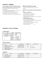
...measure against static electricity. • During operations, disconnect the AC cord from (SRV′) position. GENERAL This manual describes the ER-A310/A330 disassembly procedures and the option attachment procedures. NAME 1 SRV KEY 2 MODE KEYGRIP COVER 3 DRIP-PROOF KEYBOARD COVER 4 SHIELD PLATE...BE BL DESCRIPTIONS OP key only Only for default keyboard layout. for ER-A330 3. Supplies No. CHAPTER 2. NAME 1 ROLL PAPER 2 INK ROLLER (ER-A310) 3 INK ROLLER (ER-A330) 4 INK FOR STAMP PARTS CODE DPAPR1006CSZZ NRÇLR6652RCZZ NRÇLR6638RCZZ UINK-1001CCZZ PRICE RANK AR...
...measure against static electricity. • During operations, disconnect the AC cord from (SRV′) position. GENERAL This manual describes the ER-A310/A330 disassembly procedures and the option attachment procedures. NAME 1 SRV KEY 2 MODE KEYGRIP COVER 3 DRIP-PROOF KEYBOARD COVER 4 SHIELD PLATE...BE BL DESCRIPTIONS OP key only Only for default keyboard layout. for ER-A330 3. Supplies No. CHAPTER 2. NAME 1 ROLL PAPER 2 INK ROLLER (ER-A310) 3 INK ROLLER (ER-A330) 4 INK FOR STAMP PARTS CODE DPAPR1006CSZZ NRÇLR6652RCZZ NRÇLR6638RCZZ UINK-1001CCZZ PRICE RANK AR...
Installation Manual
Page 6
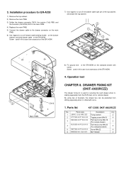
... L2 R55 R56 15K 56K R57 ER-A310:3.3K ER-A330:4.7K CN11 STANDARD DRAWER DR2 ER-A310:R80 ER-A330:R89 1K VP:+24V CN16 ER-A310:Q20 ER-A330:Q14 C3784 OPTION DRAWER 5) Connect the drawer cable to the drawer connector on the drawer connector The main PWB has no part for ER-A310 1) Remove the top cabinet. 2) Remove...
... L2 R55 R56 15K 56K R57 ER-A310:3.3K ER-A330:4.7K CN11 STANDARD DRAWER DR2 ER-A310:R80 ER-A330:R89 1K VP:+24V CN16 ER-A310:Q20 ER-A330:Q14 C3784 OPTION DRAWER 5) Connect the drawer cable to the drawer connector on the drawer connector The main PWB has no part for ER-A310 1) Remove the top cabinet. 2) Remove...
Installation Manual
Page 7
...with screw #. Parts code Description Q'ty 1 LBRC–2321RCZZ Fixing bracket 2 2 XTPSD40P16000 Tapping screw M4x16 4 3 XBSSD40P16000 Flat head screw M4x16 (For remote drawer) 2 4 XUSSD40P20000 Flat head screw M4x20 (For standard drawer) 2 5 XBPSD40P22000 Screw M4x22 4 6 XNESD40–32000 NUT M4x32 4 – 6 – Screw ! Screw # used for ER-A330 1) Remove the... drawer. DRAWER FIXING KIT (DKIT-8633RCZZ) The drawer fixing kit is used in this case is an accessory of the ER-04DW. Parts list KIT CODE: DKIT-8633RCZZ Main PWB. Operation test CHAPTER 8.
...with screw #. Parts code Description Q'ty 1 LBRC–2321RCZZ Fixing bracket 2 2 XTPSD40P16000 Tapping screw M4x16 4 3 XBSSD40P16000 Flat head screw M4x16 (For remote drawer) 2 4 XUSSD40P20000 Flat head screw M4x20 (For standard drawer) 2 5 XBPSD40P22000 Screw M4x22 4 6 XNESD40–32000 NUT M4x32 4 – 6 – Screw ! Screw # used for ER-A330 1) Remove the... drawer. DRAWER FIXING KIT (DKIT-8633RCZZ) The drawer fixing kit is used in this case is an accessory of the ER-04DW. Parts list KIT CODE: DKIT-8633RCZZ Main PWB. Operation test CHAPTER 8.
Installation Manual
Page 8
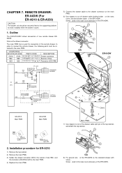
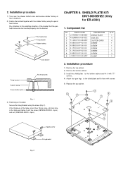
...screw Fig. 1 3) Fastening on the table: Secure the fixing Bracket using the pand hand screw. Pay attention for ER-A330) 1. If the thickness of the bracket that the pan head screw can be inserted properly into the bracket. Component list... of the table is less than 15mm, bore a 4.5mm hole in the table and fasten it with the rubber footing using the screw (Fig. 2). CHAPTER 9. PARTS CODE DESCRIPTION Q'TY 1 LCHSM6705BHZZ SHIELD PLATE 1 2 PGUMM6696BHZZ GUM LEG 4 3 TLABH7054BHZZ CAUTION CARD 4 4 XUBSD30P12X00 SCREW 1 5 XUBSD30P08000 SCREW 1 6 XJPSD30P12X00 SCREW 1 ...
...screw Fig. 1 3) Fastening on the table: Secure the fixing Bracket using the pand hand screw. Pay attention for ER-A330) 1. If the thickness of the bracket that the pan head screw can be inserted properly into the bracket. Component list... of the table is less than 15mm, bore a 4.5mm hole in the table and fasten it with the rubber footing using the screw (Fig. 2). CHAPTER 9. PARTS CODE DESCRIPTION Q'TY 1 LCHSM6705BHZZ SHIELD PLATE 1 2 PGUMM6696BHZZ GUM LEG 4 3 TLABH7054BHZZ CAUTION CARD 4 4 XUBSD30P12X00 SCREW 1 5 XUBSD30P08000 SCREW 1 6 XJPSD30P12X00 SCREW 1 ...
Installation Manual
Page 9
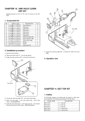
... the following key top (option) to the clerk switch body ! CN9 2. NC9 on the main PWB. 3. MODEL NAME ER-11KT7 ER-12KT7 ER-22KT7 ER-11DK7 ER-51DK7 DESCRIPTION 1 × 1 Key top 1 × 2 Key top 2 × 2 Key top 1 ×... 1 Dummy key 5 × 1 Dummy key – 8 – Operation test Top cabinet 2 3 4) Connect the clerk key cable (5P) " to the clerk switch body !. 5) Attach the clerk angle # to allow additional installation of the ERA330. 1. CHAPTER 10. Component list No. PARTS...
... the following key top (option) to the clerk switch body ! CN9 2. NC9 on the main PWB. 3. MODEL NAME ER-11KT7 ER-12KT7 ER-22KT7 ER-11DK7 ER-51DK7 DESCRIPTION 1 × 1 Key top 1 × 2 Key top 2 × 2 Key top 1 ×... 1 Dummy key 5 × 1 Dummy key – 8 – Operation test Top cabinet 2 3 4) Connect the clerk key cable (5P) " to the clerk switch body !. 5) Attach the clerk angle # to allow additional installation of the ERA330. 1. CHAPTER 10. Component list No. PARTS...


