
Service Manual
Page 1
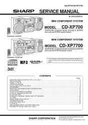
... TRANSISTOR AND LED ...18 BLOCK DIAGRAM ...19 SCHEMATIC DIAGRAM / WIRING SIDE OF P.W.BOARD 22 VOLTAGE ...40 WAVEFORMS OF CD CIRCUIT ...41 TROUBLESHOOTING ...42 FUNCTION TABLE OF IC ...46 FL DISPLAY ...57 REPLACEMENT PARTS LIST/EXPLODED VIEW PACKING OF THE SET (FOR U.S.A. Illustration: CD-XP700 Illustration: CD-XP7700 CD-XP700/CD-XP7700 SERVICE MANUAL No. ONLY) SHARP CORPORATION This document has been published to change without notice. ONLY) ...2 SPECIFICATIONS ...3 NAMES OF PARTS ...4 OPERATION MANUAL ...6 QUICK GUIDE (FOR U.S.A.
... TRANSISTOR AND LED ...18 BLOCK DIAGRAM ...19 SCHEMATIC DIAGRAM / WIRING SIDE OF P.W.BOARD 22 VOLTAGE ...40 WAVEFORMS OF CD CIRCUIT ...41 TROUBLESHOOTING ...42 FUNCTION TABLE OF IC ...46 FL DISPLAY ...57 REPLACEMENT PARTS LIST/EXPLODED VIEW PACKING OF THE SET (FOR U.S.A. Illustration: CD-XP700 Illustration: CD-XP7700 CD-XP700/CD-XP7700 SERVICE MANUAL No. ONLY) SHARP CORPORATION This document has been published to change without notice. ONLY) ...2 SPECIFICATIONS ...3 NAMES OF PARTS ...4 OPERATION MANUAL ...6 QUICK GUIDE (FOR U.S.A.
Service Manual
Page 2
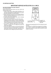
... parts having a return path to the chassis (antenna, metal cabinet, screw heads, knobs and control shafts, escutcheon, etc.) and measure the AC voltage drop across the resistor (See diagram). * Connect the resistor connection to all protective devices such as conduit or electrical ground connected to the user, perform the following manner. * Plug the AC line cord directly into a 120 volt AC outlet. * Using...
... parts having a return path to the chassis (antenna, metal cabinet, screw heads, knobs and control shafts, escutcheon, etc.) and measure the AC voltage drop across the resistor (See diagram). * Connect the resistor connection to all protective devices such as conduit or electrical ground connected to the user, perform the following manner. * Plug the AC line cord directly into a 120 volt AC outlet. * Using...
Service Manual
Page 3
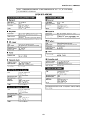
...") Depth: 355 mm (13-15/16") 7.9 kg (17.4 lbs.) Amplifier Output power Output terminals Input terminals CD player Type Signal readout D/A converter Frequency response Dynamic range Tuner Frequency range 100 watts minimum RMS per channel into 6 ohms from 60 Hz to 20 kHz, 10% total harmonic distortion Speakers: 6 ohms Headphones: 16 - 50 ohms (recommended: 32 ohms) Video/Auxiliary (audio signal): 500 mV/47 kohms 3-disc multi-play compact disc player Non-contact, 3-beam semiconductor laser pickup 1-bit D/A converter 20...
...") Depth: 355 mm (13-15/16") 7.9 kg (17.4 lbs.) Amplifier Output power Output terminals Input terminals CD player Type Signal readout D/A converter Frequency response Dynamic range Tuner Frequency range 100 watts minimum RMS per channel into 6 ohms from 60 Hz to 20 kHz, 10% total harmonic distortion Speakers: 6 ohms Headphones: 16 - 50 ohms (recommended: 32 ohms) Video/Auxiliary (audio signal): 500 mV/47 kohms 3-disc multi-play compact disc player Non-contact, 3-beam semiconductor laser pickup 1-bit D/A converter 20...

Service Manual
Page 4
...19 20 21 22 23 24 Rear panel 1. Video/Auxiliary (Audio Signal) Input Jacks 6. Extra Bass Indicator 3. Tape 2 Record Indicator 6. Timer Recording Indicator 11. Disc Tray 2. Tuner (Band) Button 5. Equalizer Mode Select/Extra Bass/ Demo Mode Button 10. Volume Up and Down Buttons 13. Disc Repeat Play Indicator 13. Headphone Jack 7. Tape 1 Cassette Compartment 14. Tuning and Time Down Button 22. Memory/Set Button 23. Transport Screw 4. CD/MP3 Disc Track Down or Fast Reverse, Tape 2 Rewind, Tuner Preset Down Button 16. Timer/Sleep Button 19. Speaker Terminals...
...19 20 21 22 23 24 Rear panel 1. Video/Auxiliary (Audio Signal) Input Jacks 6. Extra Bass Indicator 3. Tape 2 Record Indicator 6. Timer Recording Indicator 11. Disc Tray 2. Tuner (Band) Button 5. Equalizer Mode Select/Extra Bass/ Demo Mode Button 10. Volume Up and Down Buttons 13. Disc Repeat Play Indicator 13. Headphone Jack 7. Tape 1 Cassette Compartment 14. Tuning and Time Down Button 22. Memory/Set Button 23. Transport Screw 4. CD/MP3 Disc Track Down or Fast Reverse, Tape 2 Rewind, Tuner Preset Down Button 16. Timer/Sleep Button 19. Speaker Terminals...

Service Manual
Page 5
... Bass Button 11. CD/MP3 Disc Play or Repeat, Tape Play Button 6 20. Speaker Wire CP-XP700 1 2 3 3 4 CP-XP7700 1 3 3 2 4 - 5 - Equalizer Mode Select Button 2 7. Volume Up and Down Buttons 8 9 Buttons with " " mark in the illustration can be operated on the remote control only. 10 Other buttons can be operated both on the main unit and the remote control. Disc Direct Search Buttons 4. Tuner (Band) Button 8. MP3 Disc Display Button 3 12. Disc Pause Button 17. Video/Auxiliary Button 21. Disc Random Button 13. CD-XP700/CD-XP7700 Remote...
... Bass Button 11. CD/MP3 Disc Play or Repeat, Tape Play Button 6 20. Speaker Wire CP-XP700 1 2 3 3 4 CP-XP7700 1 3 3 2 4 - 5 - Equalizer Mode Select Button 2 7. Volume Up and Down Buttons 8 9 Buttons with " " mark in the illustration can be operated on the remote control only. 10 Other buttons can be operated both on the main unit and the remote control. Disc Direct Search Buttons 4. Tuner (Band) Button 8. MP3 Disc Display Button 3 12. Disc Pause Button 17. Video/Auxiliary Button 21. Disc Random Button 13. CD-XP700/CD-XP7700 Remote...
Service Manual
Page 6
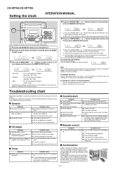
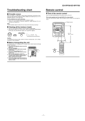
... sound is selected, "AM" will flash at the push of the unit plugged in the middle or is first installed or it down ? If the unit still malfunctions, reset it down to the power stand-by 1 minute. Cannot erase completely. Does the remote control sensor receive strong light? If this unit to advance continuously. CD-XP700/CD-XP7700 Setting the clock OPERATION MANUAL 4 Press the TUNING/TIME ( or ) button to...
... sound is selected, "AM" will flash at the push of the unit plugged in the middle or is first installed or it down ? If the unit still malfunctions, reset it down to the power stand-by 1 minute. Cannot erase completely. Does the remote control sensor receive strong light? If this unit to advance continuously. CD-XP700/CD-XP7700 Setting the clock OPERATION MANUAL 4 Press the TUNING/TIME ( or ) button to...
Service Manual
Page 7
... CLOCK button and the EQUALIZER/X-BASS/DEMO button, press the ON/STAND-BY button until "CLEAR AL" appears. Remove all data stored in memory including clock, timer settings, tuner preset, and CD program. Clearing all the memory by mode, and then unplug the AC power cord from the AC outlet. 6 Insert the transport screw into the back of the remote control Point the remote control directly at the remote sensor...
... CLOCK button and the EQUALIZER/X-BASS/DEMO button, press the ON/STAND-BY button until "CLEAR AL" appears. Remove all data stored in memory including clock, timer settings, tuner preset, and CD program. Clearing all the memory by mode, and then unplug the AC power cord from the AC outlet. 6 Insert the transport screw into the back of the remote control Point the remote control directly at the remote sensor...
Service Manual
Page 10
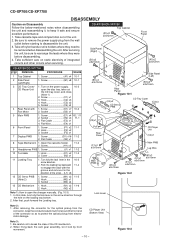
...-2 CD Player Unit open the changer manually. (Fig. 10-3) 1. Turn on static electricity of the unit. 2. Socket E2) x3 11-1 3. Hook F2) x2 3. Flat Cable G2) x1 8 Tape Mechanism 1. Be careful not to keep it lock by front movement. Screw D1) x7 10-2 Fan Motor 2. Take cassette tape and compact disc out of integrated circuits and other circuits when servicing. Hook N2...
...-2 CD Player Unit open the changer manually. (Fig. 10-3) 1. Turn on static electricity of the unit. 2. Socket E2) x3 11-1 3. Hook F2) x2 3. Flat Cable G2) x1 8 Tape Mechanism 1. Be careful not to keep it lock by front movement. Screw D1) x7 10-2 Fan Motor 2. Take cassette tape and compact disc out of integrated circuits and other circuits when servicing. Hook N2...

Service Manual
Page 14
...) x 1 pc., to remove the CD mechanism. CD-XP700/CD-XP7700 CD MECHANISM SECTION Perform steps 1, 2, 3, 10, 11,12 and 13 of connector so as to remove the pickup (See Fig. 14-2) 1. Remove the screws (B3) x 2 pcs., to 80 g.cm - - Specified Instrument Value Connection 3,000 ± 30 Hz Speaker Terminal (Load resistance: 6 ohms) TAPE MECHANISM Tape Motor - 14 - Figure 14-1 (B3...
...) x 1 pc., to remove the CD mechanism. CD-XP700/CD-XP7700 CD MECHANISM SECTION Perform steps 1, 2, 3, 10, 11,12 and 13 of connector so as to remove the pickup (See Fig. 14-2) 1. Remove the screws (B3) x 2 pcs., to 80 g.cm - - Specified Instrument Value Connection 3,000 ± 30 Hz Speaker Terminal (Load resistance: 6 ohms) TAPE MECHANISM Tape Motor - 14 - Figure 14-1 (B3...
Service Manual
Page 15
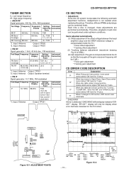
... dB) *1. former T302 fully counter- Input: Antenna Output: Speaker terminal • FM IF Signal generator: 10.7 MHz, FM modulated Test Stage Frequency Frequency Display Setting/ Instrument Adjusting Connection Point IF 10.7 MHz 98 MHz T302 *1 (Turn the core of each disc can be display when error had been detected for 7 secs. 10* When disc table rotate to Open/Close, Open/Close switch cannot detect 'ON' level for the 5 th times.
... dB) *1. former T302 fully counter- Input: Antenna Output: Speaker terminal • FM IF Signal generator: 10.7 MHz, FM modulated Test Stage Frequency Frequency Display Setting/ Instrument Adjusting Connection Point IF 10.7 MHz 98 MHz T302 *1 (Turn the core of each disc can be display when error had been detected for 7 secs. 10* When disc table rotate to Open/Close, Open/Close switch cannot detect 'ON' level for the 5 th times.

Service Manual
Page 16
..." f) "FGAN_XX" g) "RFLS_XX" key input. OFF To cancel : Power OFF key input. IL isn't done buttons make pick's slide possible. When these following key is using manual. key input. key input. Tracking OFF play . STOP - 16 - key input. Function: -CD test mode. -Enter test mode. CD TEST OPEN/CLOSE operation is input into PLAY key, track number can be in STOP mode. Laser ON. FLAT X-BASS - CD-XP700/CD-XP7700 TEST MODE • Setting the test mode Any one of test mode can be appoint directly.
..." f) "FGAN_XX" g) "RFLS_XX" key input. OFF To cancel : Power OFF key input. IL isn't done buttons make pick's slide possible. When these following key is using manual. key input. key input. Tracking OFF play . STOP - 16 - key input. Function: -CD test mode. -Enter test mode. CD TEST OPEN/CLOSE operation is input into PLAY key, track number can be in STOP mode. Laser ON. FLAT X-BASS - CD-XP700/CD-XP7700 TEST MODE • Setting the test mode Any one of test mode can be appoint directly.
Service Manual
Page 18
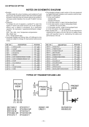
...; Schematic diagram and Wiring Side of P.W.Board for this symbol P means pico-farad and the unit of the capacitor without such a symbol is being played back. 5. NO SW714 SW715 SW716 SW717 SW718 SW719 SW720 SW721 SW722 SW723 SW724 SW725 DESCRIPTION VIDEO/AUX TIMER/SLEEP TUNING/TIME UP REC PAUSE MEMORY/SET TUNING/TIME DOWN CLOCK VOLUME UP VOLUME DOWN DISC SKIP OPEN/CLOSE EQUALIZER/X-BASS/DEMO POSITION...
...; Schematic diagram and Wiring Side of P.W.Board for this symbol P means pico-farad and the unit of the capacitor without such a symbol is being played back. 5. NO SW714 SW715 SW716 SW717 SW718 SW719 SW720 SW721 SW722 SW723 SW724 SW725 DESCRIPTION VIDEO/AUX TIMER/SLEEP TUNING/TIME UP REC PAUSE MEMORY/SET TUNING/TIME DOWN CLOCK VOLUME UP VOLUME DOWN DISC SKIP OPEN/CLOSE EQUALIZER/X-BASS/DEMO POSITION...

Service Manual
Page 21
...POWER AMP. +B5 0dB TT Q601 Q602 Q603 Q604 REC/PLAY T1/T2 BIAS M SYSTEM MUTE VF1 -VF VF2 IC851 KIA7812AP VOLTAGE REGULATOR CD-XP700/CD-XP7700 FL701 FL DISPLAY 1 5 ~ 12 13 14 ~ 19 27 ~ 32 33 ~41 +B9 Q705 45 +B10 TO CD SECTION TAPE...REMOTE 1 SENSOR 3 2 +B10 KEY SW701-SW705 SW711-SW725 +B10 SP DET. L 18 11 L-OUT R 14 7 6 251 8 R-OUT +B1 -B1 +B10 XL700 4.194304 MHz TO CD SECTION RESET Q709 +B10 FAN MOTOR DRIVER Q906 +B7 M4 M FAN MOTOR Q901~ Q904 SP RELAY ON-OFF Q905 RL914 SO901 SPEAKER TERMINAL +B3 D801 PT801 POWER...POWER SUPPLY CORD AC 120 V, 60 Hz Figure 21 BLOCK...
...POWER AMP. +B5 0dB TT Q601 Q602 Q603 Q604 REC/PLAY T1/T2 BIAS M SYSTEM MUTE VF1 -VF VF2 IC851 KIA7812AP VOLTAGE REGULATOR CD-XP700/CD-XP7700 FL701 FL DISPLAY 1 5 ~ 12 13 14 ~ 19 27 ~ 32 33 ~41 +B9 Q705 45 +B10 TO CD SECTION TAPE...REMOTE 1 SENSOR 3 2 +B10 KEY SW701-SW705 SW711-SW725 +B10 SP DET. L 18 11 L-OUT R 14 7 6 251 8 R-OUT +B1 -B1 +B10 XL700 4.194304 MHz TO CD SECTION RESET Q709 +B10 FAN MOTOR DRIVER Q906 +B7 M4 M FAN MOTOR Q901~ Q904 SP RELAY ON-OFF Q905 RL914 SO901 SPEAKER TERMINAL +B3 D801 PT801 POWER...POWER SUPPLY CORD AC 120 V, 60 Hz Figure 21 BLOCK...
Service Manual
Page 42
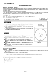
... below." Turn the power off any adjustment make certain that the lens is dirty, this product is displayed. (1) Check the power to come in the cleaner cap, apply 1 or 2 drops of the cleaning fluid to turn, press the stop . Pressing the CD operation key is taken, check the following items. Remove the cabinet and follow the trouble shooting instructions. Using the...
... below." Turn the power off any adjustment make certain that the lens is dirty, this product is displayed. (1) Check the power to come in the cleaner cap, apply 1 or 2 drops of the cleaning fluid to turn, press the stop . Pressing the CD operation key is taken, check the following items. Remove the cabinet and follow the trouble shooting instructions. Using the...

Service Manual
Page 46
... reading clock input terminal/FG signal input terminal/external emphasis setting terminal. Internal signal monitor terminal 5. FIN1 Input - Output terminal for test. Servo D/A general-purpose output terminal. The status changes to "H" when the sync signal detected in Reset SLCO Output - TIN2 Input - RF power terminal. RF internal signal monitor terminal. E signal input terminal. Digital OUT output terminal. (EIAJ format) Input terminal for tracking control. Left channel D/A converter Power supply for Left channel. ADAVSS - - CD-XP700/CD-XP7700 FUNCTION TABLE OF...
... reading clock input terminal/FG signal input terminal/external emphasis setting terminal. Internal signal monitor terminal 5. FIN1 Input - Output terminal for test. Servo D/A general-purpose output terminal. The status changes to "H" when the sync signal detected in Reset SLCO Output - TIN2 Input - RF power terminal. RF internal signal monitor terminal. E signal input terminal. Digital OUT output terminal. (EIAJ format) Input terminal for tracking control. Left channel D/A converter Power supply for Left channel. ADAVSS - - CD-XP700/CD-XP7700 FUNCTION TABLE OF...

Service Manual
Page 47
... be connect to 0 V, or set LOW after first applied power on. 67 DRF Output L Focus detection output port. 68 VDD5 Input - Must be connected to 0 V. When not used, General purpose input/ output terminal 7. PLL GND for Right channel. Right channel output. Chip reset signal input port. LVDD /2 - Chip enable signal input port. 62 CL Input - Power supply for crystal oscillator. Must be connected to 0 V.) 57 ASDFIN Input - Must be connect to 0 V. CD-XP700/CD-XP7700 IC1 VHiLC78645NE1: CD...
... be connect to 0 V, or set LOW after first applied power on. 67 DRF Output L Focus detection output port. 68 VDD5 Input - Must be connected to 0 V. When not used, General purpose input/ output terminal 7. PLL GND for Right channel. Right channel output. Chip reset signal input port. LVDD /2 - Chip enable signal input port. 62 CL Input - Power supply for crystal oscillator. Must be connected to 0 V.) 57 ASDFIN Input - Must be connect to 0 V. CD-XP700/CD-XP7700 IC1 VHiLC78645NE1: CD...

Service Manual
Page 55
... 2-KEY 0 Input Input Speaker output level detect. Key input. 34 AVDD AVDD - Output Ground voltage. Port Name Terminal Name Input/Output Function 1 VDD 2 P37 VDD -20dBATT Input Output (+) Power supply. -20dB Attenuator. 3 P36 4 P35 SUB_CE T_BIAS Output Output MP3 sub microcomputer. CD-XP700/CD-XP7700 IC701 RH-iX0499AWZZ: System Microcomputer (IX0499AW) (1/2) Pin No. Tape record bias. 5 P34 T_T1/T2 Output Tape T1/T2 change. 6 P33 T_REC/PLY Output Tape REC/PLAY change. 7 P32 CD_RESOUT Output CD DSP reset. 8 P31 CD WRQ Input CD write...
... 2-KEY 0 Input Input Speaker output level detect. Key input. 34 AVDD AVDD - Output Ground voltage. Port Name Terminal Name Input/Output Function 1 VDD 2 P37 VDD -20dBATT Input Output (+) Power supply. -20dB Attenuator. 3 P36 4 P35 SUB_CE T_BIAS Output Output MP3 sub microcomputer. CD-XP700/CD-XP7700 IC701 RH-iX0499AWZZ: System Microcomputer (IX0499AW) (1/2) Pin No. Tape record bias. 5 P34 T_T1/T2 Output Tape T1/T2 change. 6 P33 T_REC/PLY Output Tape REC/PLAY change. 7 P32 CD_RESOUT Output CD DSP reset. 8 P31 CD WRQ Input CD write...
Service Manual
Page 59
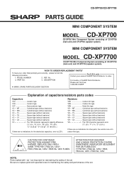
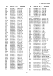
... wire) VC J .. "HOW TO ORDER REPLACEMENT PARTS" To have your nearest SHARP Parts Distributor to replace parts with " " are ±5% carbon-film type. Be sure to order. 3. MODEL NUMBER 2. REF. PART NO. 4. No. DESCRIPTION For location of SHARP Parts Distributor, Please call Toll-Free; 1-800-BE-SHARP MARK: SPARE PARTS-DELIVERY SECTION Explanation of the set . MINI COMPONENT SYSTEM MODEL CD-XP7700 CD-XP7700 Mini Component System consisting of CD-XP700 (main unit) and CP-XP700 (speaker...
... wire) VC J .. "HOW TO ORDER REPLACEMENT PARTS" To have your nearest SHARP Parts Distributor to replace parts with " " are ±5% carbon-film type. Be sure to order. 3. MODEL NUMBER 2. REF. PART NO. 4. No. DESCRIPTION For location of SHARP Parts Distributor, Please call Toll-Free; 1-800-BE-SHARP MARK: SPARE PARTS-DELIVERY SECTION Explanation of the set . MINI COMPONENT SYSTEM MODEL CD-XP7700 CD-XP7700 Mini Component System consisting of CD-XP700 (main unit) and CP-XP700 (speaker...
Service Manual
Page 63
... [Disc Number] AD Switch,Leaf Type [Pickup In] AC Switch,Key Type [Power] AC Switch,Key Type [Fast Rewind/Preset Down] AC Switch,Key Type [Fast Forward/Preset Up] AC Switch,Key Type [Stop] AC Switch,Key Type [Play/Repeat] AC Switch,Key Type [CD] AC Switch,Key Type [Tuner (Band)] AC Switch,Key Type [Tape] AC Switch,Key Type [Video/Aux] AC Switch,Key Type [Timer/Sleep] AC Switch,Key Type [Tuning/Time Up...
... [Disc Number] AD Switch,Leaf Type [Pickup In] AC Switch,Key Type [Power] AC Switch,Key Type [Fast Rewind/Preset Down] AC Switch,Key Type [Fast Forward/Preset Up] AC Switch,Key Type [Stop] AC Switch,Key Type [Play/Repeat] AC Switch,Key Type [CD] AC Switch,Key Type [Tuner (Band)] AC Switch,Key Type [Tape] AC Switch,Key Type [Video/Aux] AC Switch,Key Type [Timer/Sleep] AC Switch,Key Type [Tuning/Time Up...

Service Manual
Page 64
... 1] AE Holder,Cassette [Tape 2] AE Panel,Cassette [Tape 1] [CD-XP700] AE Panel,Cassette [Tape 1] [CD-XP7700] AE Panel,Cassette [Tape 2] [CD-XP700] AE Panel,Cassette [Tape 2] [CD-XP7700] AL Panel,Amp. [CD-XP700] AL Panel,Amp. [CD-XP7700] AE Ring,Play/Stop AH Button,Volume [CD-XP700] Button,Volume [CD-XP7700] AK Button,Operation [CD-XP700] AH Button,Operation [CD-XP7700] AC Button,X-Bass/Equalizer [CD-XP700] AD Button,X-Bass/Equalizer [CD-XP7700] AD Button,Function [CD-XP700] AD Button,Function [CD-XP7700] AF Button,Power [CD-XP700] AE Button,Power [CD-XP7700] AF Block,Button AD Damper AB Spring...
... 1] AE Holder,Cassette [Tape 2] AE Panel,Cassette [Tape 1] [CD-XP700] AE Panel,Cassette [Tape 1] [CD-XP7700] AE Panel,Cassette [Tape 2] [CD-XP700] AE Panel,Cassette [Tape 2] [CD-XP7700] AL Panel,Amp. [CD-XP700] AL Panel,Amp. [CD-XP7700] AE Ring,Play/Stop AH Button,Volume [CD-XP700] Button,Volume [CD-XP7700] AK Button,Operation [CD-XP700] AH Button,Operation [CD-XP7700] AC Button,X-Bass/Equalizer [CD-XP700] AD Button,X-Bass/Equalizer [CD-XP7700] AD Button,Function [CD-XP700] AD Button,Function [CD-XP7700] AF Button,Power [CD-XP700] AE Button,Power [CD-XP7700] AF Block,Button AD Damper AB Spring...


