
Service Manual
Page 1
CD-XP200/CD-XP2200 SERVICE MANUAL No. ONLY) SHARP CORPORATION This document has been published to be used for after sales service only. S1206CDXP200/ MINI COMPONENT SYSTEM MODEL CD-XP200 CD-XP200 Mini Component System consisting of user-safety the set should be restored to its original condition and only parts identical to change without notice. ONLY) ...8 DISASSEMBLY ...10 REMOVING AND REINSTALLING THE MAIN PARTS 13 ADJUSTMENT ...14 NOTES ON SCHEMATIC DIAGRAM ...18 TYPES OF...
CD-XP200/CD-XP2200 SERVICE MANUAL No. ONLY) SHARP CORPORATION This document has been published to be used for after sales service only. S1206CDXP200/ MINI COMPONENT SYSTEM MODEL CD-XP200 CD-XP200 Mini Component System consisting of user-safety the set should be restored to its original condition and only parts identical to change without notice. ONLY) ...8 DISASSEMBLY ...10 REMOVING AND REINSTALLING THE MAIN PARTS 13 ADJUSTMENT ...14 NOTES ON SCHEMATIC DIAGRAM ...18 TYPES OF...
Service Manual
Page 2
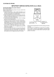
... EXPOSED METAL PARTS 0.15 µF TEST PROBE CONNECT TO KNOWN EARTH GROUND All check must be repeated with 1000 ohm per volt, or higher, sensitivity to all protective devices such as conduit or electrical ground connected to the user, perform the following manner. * Plug the AC line cord directly into a 120 volt AC outlet. * Using two clip leads, connect a 1.5 kohm, 10 watt resistor...
... EXPOSED METAL PARTS 0.15 µF TEST PROBE CONNECT TO KNOWN EARTH GROUND All check must be repeated with 1000 ohm per volt, or higher, sensitivity to all protective devices such as conduit or electrical ground connected to the user, perform the following manner. * Plug the AC line cord directly into a 120 volt AC outlet. * Using two clip leads, connect a 1.5 kohm, 10 watt resistor...

Service Manual
Page 3
.... (6.6 kg) Amplifier Output power Output terminals Input terminals 75 watts minimum RMS per channel into 6 ohms from 60 Hz to 20 kHz, 10% total harmonic distortion Speakers: 6 ohms Headphones: 16 - 50 ohms (recommended: 32 ohms) Video/Auxiliary (audio signal): 500 mV/47 kohms CD player Type Signal readout D/A converter Frequency response Dynamic range 3-disc multi-play compact disc player Non-contact, 3-beam semiconductor laser pickup 1-bit D/A converter 20 - 20,000 Hz 90 dB (1 kHz) Tuner Frequency range FM: 87...
.... (6.6 kg) Amplifier Output power Output terminals Input terminals 75 watts minimum RMS per channel into 6 ohms from 60 Hz to 20 kHz, 10% total harmonic distortion Speakers: 6 ohms Headphones: 16 - 50 ohms (recommended: 32 ohms) Video/Auxiliary (audio signal): 500 mV/47 kohms CD player Type Signal readout D/A converter Frequency response Dynamic range 3-disc multi-play compact disc player Non-contact, 3-beam semiconductor laser pickup 1-bit D/A converter 20 - 20,000 Hz 90 dB (1 kHz) Tuner Frequency range FM: 87...

Service Manual
Page 4
...Set Indicator 3. Tuner (Band) Button 5. Headphone Jack 7. Equalizer Mode Select/Extra Bass/Demo Mode Button 10. Clock Button 18. Cooling Fan 2. AC Power Cord 3. Sleep Indicator 9. Disc Tray 7 2. CD Button 5 8 9 6. Video/Auxiliary Button 9. CD Play or Repeat, Tape Play Button 20. Tape 2 Record Pause Button 19 20 21 22 23 24 24. Tuning and Time Up Button Rear panel 1. Transport Screw 4. Tape 2 Record Indicator 5. Tape Play Indicator 13. Tape (1 2) Button 6 10 8. Tape 1 Cassette Compartment 14. CD or Tape Stop Button 21. FM/AM Loop Antenna...
...Set Indicator 3. Tuner (Band) Button 5. Headphone Jack 7. Equalizer Mode Select/Extra Bass/Demo Mode Button 10. Clock Button 18. Cooling Fan 2. AC Power Cord 3. Sleep Indicator 9. Disc Tray 7 2. CD Button 5 8 9 6. Video/Auxiliary Button 9. CD Play or Repeat, Tape Play Button 20. Tape 2 Record Pause Button 19 20 21 22 23 24 24. Tuning and Time Up Button Rear panel 1. Transport Screw 4. Tape 2 Record Indicator 5. Tape Play Indicator 13. Tape (1 2) Button 6 10 8. Tape 1 Cassette Compartment 14. CD or Tape Stop Button 21. FM/AM Loop Antenna...

Service Manual
Page 5
... Pause Button 7. CD or Tape Stop Button 9. Equalizer Mode Select Button 14. CD Random Button 5. CD Track Down or Fast Reverse, Tape 2 Rewind Button 8. CD Button 11. CD Pause Button 17. Woofer 3. Bass Reflex Duct 4. Extra Bass Button 13. Tuner Preset Up and Down Buttons 16. CD Play or Repeat, Tape Play Button 19. Tweeter 2. Speaker Wire 1 2 3 3 4 - 5 - Tuner (Band) Button 10. Volume Up and Down Buttons Buttons with " " mark in the illustration can be operated on the main unit and the remote control. Tape (1 2) Button 20. CD Clear Button 15. Power On...
... Pause Button 7. CD or Tape Stop Button 9. Equalizer Mode Select Button 14. CD Random Button 5. CD Track Down or Fast Reverse, Tape 2 Rewind Button 8. CD Button 11. CD Pause Button 17. Woofer 3. Bass Reflex Duct 4. Extra Bass Button 13. Tuner Preset Up and Down Buttons 16. CD Play or Repeat, Tape Play Button 19. Tweeter 2. Speaker Wire 1 2 3 3 4 - 5 - Tuner (Band) Button 10. Volume Up and Down Buttons Buttons with " " mark in the illustration can be operated on the main unit and the remote control. Tape (1 2) Button 20. CD Clear Button 15. Power On...
Service Manual
Page 6
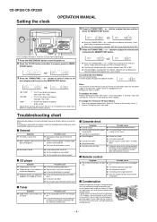
... sound quality. Do not open the compartment forcibly. Is the distance or angle incorrect? CD-XP200/CD-XP2200 Setting the clock OPERATION MANUAL 4 Press the TUNING/TIME ( or ) button to select 12-hour or 24- When the 12-hour display is flashing, step 3 (for selecting the 12-hour or 24-hour display) will flash at the push of the CLOCK button when the AC power supply is first installed...
... sound quality. Do not open the compartment forcibly. Is the distance or angle incorrect? CD-XP200/CD-XP2200 Setting the clock OPERATION MANUAL 4 Press the TUNING/TIME ( or ) button to select 12-hour or 24- When the 12-hour display is flashing, step 3 (for selecting the 12-hour or 24-hour display) will flash at the push of the CLOCK button when the AC power supply is first installed...
Service Manual
Page 7
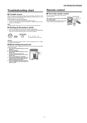
...: This operation will erase all the memory by resetting it. Clearing all CDs inserted in memory including clock, timer settings, tuner preset, and CD program. Now, you can be used within the range shown: Press the ON/STAND-BY button. Make sure that "NO DISC" is displayed. 5 Press the ON/STAND-BY button to enter the stand-by mode, and then unplug the AC power cord from...
...: This operation will erase all the memory by resetting it. Clearing all CDs inserted in memory including clock, timer settings, tuner preset, and CD program. Now, you can be used within the range shown: Press the ON/STAND-BY button. Make sure that "NO DISC" is displayed. 5 Press the ON/STAND-BY button to enter the stand-by mode, and then unplug the AC power cord from...

Service Manual
Page 10
... CD-XP200/CD-XP2200 STEP REMOVAL PROCEDURE FIGURE 1 Top Cabinet 1. Turn on static electricity of the arrow. .. (L1) x6 10-3 11-4 12 CD Servo PWB (Note 2) 1. Screw C1) x1 3. Figure 10-3 - 10 - Take cassette tape and compact disc out of the CD mechanism. 2. Screw B1) x8 10-1 3 CD Tray Cover/ 1. Flat Wire E4) x1 6 Front Panel 1. Turn fully the lock lever in the direction...
... CD-XP200/CD-XP2200 STEP REMOVAL PROCEDURE FIGURE 1 Top Cabinet 1. Turn on static electricity of the arrow. .. (L1) x6 10-3 11-4 12 CD Servo PWB (Note 2) 1. Screw C1) x1 3. Figure 10-3 - 10 - Take cassette tape and compact disc out of the CD mechanism. 2. Screw B1) x8 10-1 3 CD Tray Cover/ 1. Flat Wire E4) x1 6 Front Panel 1. Turn fully the lock lever in the direction...

Service Manual
Page 14
... the pickup (See Fig. 14-2) 1. CD-XP200/CD-XP2200 CD MECHANISM SECTION Perform steps 1, 2, 3, 10, 11,12 and 13 of connector so as to protect the optical pickup from electrostatic damage. Loading Tray Loading ...Tape Speed Test Tape Normal MTT-111 speed Adjusting Point Variable Resistor in motor Figure 14-3 Remove the pickup. Bend the hooks (A1) x 6 pcs., to remove the gear (B2) x 1 pc. 2. Variable Resistor in motor. How to remove the CD mechanism. Specified Instrument Value Connection 3,000 ± 30 Hz Speaker Terminal (Load resistance: 6 ohms) TAPE MECHANISM Tape...
... the pickup (See Fig. 14-2) 1. CD-XP200/CD-XP2200 CD MECHANISM SECTION Perform steps 1, 2, 3, 10, 11,12 and 13 of connector so as to protect the optical pickup from electrostatic damage. Loading Tray Loading ...Tape Speed Test Tape Normal MTT-111 speed Adjusting Point Variable Resistor in motor Figure 14-3 Remove the pickup. Bend the hooks (A1) x 6 pcs., to remove the gear (B2) x 1 pc. 2. Variable Resistor in motor. How to remove the CD mechanism. Specified Instrument Value Connection 3,000 ± 30 Hz Speaker Terminal (Load resistance: 6 ohms) TAPE MECHANISM Tape...
Service Manual
Page 15
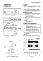
CD-XP200/CD-XP2200 TUNER SECTION fL: Low-range frequency fH: High-range frequency • AM IF/RF Signal generator: 400 Hz, 30%, AM modulated Test Stage Frequency Frequency Setting/ Instrument Display Adjusting Connection Parts AM IF 450 kHz 1,702 kHz T351 *1 AM Band - former T302 fully counter- Therefore, different PWBs and pickups can be 0 dB.) * Focus gain adjustment * Tracking gain adjustment CD ERROR CODE DESCRIPTION Error Explanation When Pickup set to CD function, DSP cannot read 31 initial...
CD-XP200/CD-XP2200 TUNER SECTION fL: Low-range frequency fH: High-range frequency • AM IF/RF Signal generator: 400 Hz, 30%, AM modulated Test Stage Frequency Frequency Setting/ Instrument Display Adjusting Connection Parts AM IF 450 kHz 1,702 kHz T351 *1 AM Band - former T302 fully counter- Therefore, different PWBs and pickups can be 0 dB.) * Focus gain adjustment * Tracking gain adjustment CD ERROR CODE DESCRIPTION Error Explanation When Pickup set to CD function, DSP cannot read 31 initial...

Service Manual
Page 16
.... Laser ON. Adjustment result automatically will display as follows. + + TEST: CD operation test. CENTER P.GEQ - Do normal play from that specific point. Tracking OFF play at that specific point. key input. STOP - 16 - Function: -CD test mode. -Enter test mode. key input. Last memory BAL - FLAT X-BASS - key input. When these following key is using manual. IL isn't done buttons make pick's slide possible. CD TEST OPEN/CLOSE operation is input into PLAY key, track number can be set c) Tracking balance d) Tracking...
.... Laser ON. Adjustment result automatically will display as follows. + + TEST: CD operation test. CENTER P.GEQ - Do normal play from that specific point. Tracking OFF play at that specific point. key input. STOP - 16 - Function: -CD test mode. -Enter test mode. key input. Last memory BAL - FLAT X-BASS - key input. When these following key is using manual. IL isn't done buttons make pick's slide possible. CD TEST OPEN/CLOSE operation is input into PLAY key, track number can be set c) Tracking balance d) Tracking...
Service Manual
Page 18
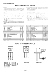
...SW724 SW725 DESCRIPTION VIDEO/AUX TIMER/SLEEP TUNING/TIME UP REC PAUSE MEMORY/SET TUNING/TIME DOWN CLOCK VOLUME UP VOLUME DOWN DISC SKIP OPEN/CLOSE EQUALIZER/X-BASS/DEMO POSITION ON-...tuner section, indicates AM indicates FM stereo 2. As to replace these parts with specified ones for improvement without any symbol is used: this model are subject to change for maintaining the safety and performance of capacitor, a symbol P is ohm-type resistor. In the power section, a tape is stopped. • Parts marked with no signal given. 1. In the CD section, the CD is being played...
...SW724 SW725 DESCRIPTION VIDEO/AUX TIMER/SLEEP TUNING/TIME UP REC PAUSE MEMORY/SET TUNING/TIME DOWN CLOCK VOLUME UP VOLUME DOWN DISC SKIP OPEN/CLOSE EQUALIZER/X-BASS/DEMO POSITION ON-...tuner section, indicates AM indicates FM stereo 2. As to replace these parts with specified ones for improvement without any symbol is used: this model are subject to change for maintaining the safety and performance of capacitor, a symbol P is ohm-type resistor. In the power section, a tape is stopped. • Parts marked with no signal given. 1. In the CD section, the CD is being played...

Service Manual
Page 21
VOLTAGE REGULATOR AC POWER SUPPLY CORD AC 120 V, 60 Hz Figure 21 BLOCK DIAGRAM (3/3) - 21 - IC901 STK4029S POWER AMP. CD-XP200/CD-XP2200 +B5 0dB TT Q601 Q602 Q603 Q604 REC/PLAY T1/T2 BIAS M SYSTEM MUTE VF1 -VF VF2 FL701 FL DISPLAY 1 5 ~ 12 13 14 ~ 19 27 ~ 32 33 ~41 +B9 Q705 45 +B10 TO CD SECTION TAPE MECHANISM ASS'Y VDD 38...
VOLTAGE REGULATOR AC POWER SUPPLY CORD AC 120 V, 60 Hz Figure 21 BLOCK DIAGRAM (3/3) - 21 - IC901 STK4029S POWER AMP. CD-XP200/CD-XP2200 +B5 0dB TT Q601 Q602 Q603 Q604 REC/PLAY T1/T2 BIAS M SYSTEM MUTE VF1 -VF VF2 FL701 FL DISPLAY 1 5 ~ 12 13 14 ~ 19 27 ~ 32 33 ~41 +B9 Q705 45 +B10 TO CD SECTION TAPE MECHANISM ASS'Y VDD 38...

Service Manual
Page 41
... not operate. Gently clean the lens with a lens cleaning tissue and a small amount of the RESET terminal (pin 66 on computer CD-ROM drives. CD optical pickup Lens cleaner disc Parts code UDSKA0004AFZZ HOW TO USE 1. Cleaner disc When a CD cannot be used on car CD players or on IC1). (2) Does the pickup move to the PICKUP-IN Switch (SW4) position? "E-CD01" is displayed. (1) Check the power...
... not operate. Gently clean the lens with a lens cleaning tissue and a small amount of the RESET terminal (pin 66 on computer CD-ROM drives. CD optical pickup Lens cleaner disc Parts code UDSKA0004AFZZ HOW TO USE 1. Cleaner disc When a CD cannot be used on car CD players or on IC1). (2) Does the pickup move to the PICKUP-IN Switch (SW4) position? "E-CD01" is displayed. (1) Check the power...

Service Manual
Page 45
... in Reset Function 1 SLCO 2 SLCIST 3 EFMIN Output Input Input - Control output. Resistor connection terminal for servo A/D, D/A. 19 ADAVSS - - RF power terminal. 6 RFVSS - - Reference supply setting terminal. 13* FE Output ZHI FE signal monitor terminal. 14 TEC Output - Power terminal for SLCO output current setting. - When not used , set them as output Subcode reading clock input terminal. "H": rough servo, "L": phase servo. 31* FSEQ Output L Sync signal detection output terminal. Digital system earth terminal. Left channel output...
... in Reset Function 1 SLCO 2 SLCIST 3 EFMIN Output Input Input - Control output. Resistor connection terminal for servo A/D, D/A. 19 ADAVSS - - RF power terminal. 6 RFVSS - - Reference supply setting terminal. 13* FE Output ZHI FE signal monitor terminal. 14 TEC Output - Power terminal for SLCO output current setting. - When not used , set them as output Subcode reading clock input terminal. "H": rough servo, "L": phase servo. 31* FSEQ Output L Sync signal detection output terminal. Digital system earth terminal. Left channel output...

Service Manual
Page 46
... power control signal output port. In this port does not use , must be connected to 0 V. 70 CONT3 71 CONT2 72* CONT1 Input/Output Input/Output Input/Output Input Input Input General purpose port 1. Output Input - Right channel D/A converter GND for crystal oscillator. Power supply for the 33.8688 MHz crystal oscillator ciement. - 50 FSX/16MIN Input/Output Input 7.35 kHz Synchronization signal monitor port. Oscillator Connected for crystal oscillator. Chip enable signal input port. 62 CL Input - Chip reset signal input...
... power control signal output port. In this port does not use , must be connected to 0 V. 70 CONT3 71 CONT2 72* CONT1 Input/Output Input/Output Input/Output Input Input Input General purpose port 1. Output Input - Right channel D/A converter GND for crystal oscillator. Power supply for the 33.8688 MHz crystal oscillator ciement. - 50 FSX/16MIN Input/Output Input 7.35 kHz Synchronization signal monitor port. Oscillator Connected for crystal oscillator. Chip enable signal input port. 62 CL Input - Chip reset signal input...

Service Manual
Page 49
... SP_DET Input Speaker abnormal detect. 39 INTP0 REMOCON Input Remocon input. 40 VSS VSS - GND 14* XT2 XT2 - Port Name Terminal Name Input/Output Function 1 VDD VDD Input (+) Power supply. 2 P37 -20dBATT Output -20dB Attenuator. 3* P36 NO USE Output Open 4 P35 T_BIAS Output Tape record bias. 5 P34 T_T1/T2 Output Tape T1/T2 change. 6 P33 T_REC/PLY Output Tape REC/PLAY change. 7 P32 CD_RESOUT Output CD DSP reset. 8 P31 CD WRQ Input CD write read request.. 9 P30 NO USE Input Connect...
... SP_DET Input Speaker abnormal detect. 39 INTP0 REMOCON Input Remocon input. 40 VSS VSS - GND 14* XT2 XT2 - Port Name Terminal Name Input/Output Function 1 VDD VDD Input (+) Power supply. 2 P37 -20dBATT Output -20dB Attenuator. 3* P36 NO USE Output Open 4 P35 T_BIAS Output Tape record bias. 5 P34 T_T1/T2 Output Tape T1/T2 change. 6 P33 T_REC/PLY Output Tape REC/PLAY change. 7 P32 CD_RESOUT Output CD DSP reset. 8 P31 CD WRQ Input CD write read request.. 9 P30 NO USE Input Connect...
Service Manual
Page 53
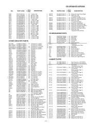
...%. PARTS GUIDE CD-XP200/CD-XP2200 MINI COMPONENT SYSTEM MODEL CD-XP200 CD-XP200 Mini Component System consisting of CD-XP2200 (main unit) and CP-XP2200 (speaker system). MINI COMPONENT SYSTEM MODEL CD-XP2200 CD-XP2200 Mini Component System consisting of CD-XP200 (main unit) and CP-XP200 (speaker system). REF. For U.S.A. only Contact your order filled promptly and correctly, please furnish the following information. 1. Be sure to order. 3. "HOW TO ORDER REPLACEMENT PARTS" To have your nearest SHARP Parts Distributor...
...%. PARTS GUIDE CD-XP200/CD-XP2200 MINI COMPONENT SYSTEM MODEL CD-XP200 CD-XP200 Mini Component System consisting of CD-XP2200 (main unit) and CP-XP2200 (speaker system). MINI COMPONENT SYSTEM MODEL CD-XP2200 CD-XP2200 Mini Component System consisting of CD-XP200 (main unit) and CP-XP200 (speaker system). REF. For U.S.A. only Contact your order filled promptly and correctly, please furnish the following information. 1. Be sure to order. 3. "HOW TO ORDER REPLACEMENT PARTS" To have your nearest SHARP Parts Distributor...
Service Manual
Page 57
... Panel,Cassette [Tape 2] [CD-XP200] Panel,Cassette [Tape 2] [CD-XP2200] Panel,Amp. [CD-XP200] Panel,Amp. [CD-XP2200] AC Ring,Play/Stop [CD-XP200] Ring,Play/Stop [CD-XP2200] AH Panel,FL Display AH Button,Volume [CD-XP200] Button,Volume [CD-XP2200] AK Button,Operation [CD-XP200] Button,Operation [CD-XP2200] AC Button,X-Bass/Equalizer [CD-XP200] Button,X-Bass/Equalizer [CD-XP2200] AD Button,Function [CD-XP200] Button,Function [CD-XP2200] AF Button,Power [CD-XP200] Button,Power [CD-XP2200] AF Block,Button AD Damper AB Spring,Cassette [Tape 1] AB Spring,Cassette [Tape 2] - 4 - PARTS CODE PRICE...
... Panel,Cassette [Tape 2] [CD-XP200] Panel,Cassette [Tape 2] [CD-XP2200] Panel,Amp. [CD-XP200] Panel,Amp. [CD-XP2200] AC Ring,Play/Stop [CD-XP200] Ring,Play/Stop [CD-XP2200] AH Panel,FL Display AH Button,Volume [CD-XP200] Button,Volume [CD-XP2200] AK Button,Operation [CD-XP200] Button,Operation [CD-XP2200] AC Button,X-Bass/Equalizer [CD-XP200] Button,X-Bass/Equalizer [CD-XP2200] AD Button,Function [CD-XP200] Button,Function [CD-XP2200] AF Button,Power [CD-XP200] Button,Power [CD-XP2200] AF Block,Button AD Damper AB Spring,Cassette [Tape 1] AB Spring,Cassette [Tape 2] - 4 - PARTS CODE PRICE...
Service Manual
Page 64
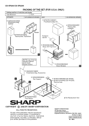
.../CD-XP2200 SPAKA0366AWZZ Packing Add., Left/Right TOP FRONT SPAKZ0891AWZZ BOTTOM Sheet, CD Tray Cover A BOTTOM AM/FM Loop Antenna Operation Manual Quick Guide Remote Control SPAKZ0885AWZZ Sheet, Miramat B SSAKA0007AWZZ Polyethylene Bag, Accessories A REAR REAR SPAKZ0895AWZZ Pad, Support B SPAKC1398AWZZ [CD-XP200] SPAKC1416AWZZ [CD-XP2200] Packing Case SPAKZ0887AWZZ Pad, Bottom Not Replacement Item COPYRIGHT © 2002 BY SHARP CORPORATION ALL RIGHTS RESERVED. ONLY) Setting position of the publisher. CD-XP200/CD-XP2200...
.../CD-XP2200 SPAKA0366AWZZ Packing Add., Left/Right TOP FRONT SPAKZ0891AWZZ BOTTOM Sheet, CD Tray Cover A BOTTOM AM/FM Loop Antenna Operation Manual Quick Guide Remote Control SPAKZ0885AWZZ Sheet, Miramat B SSAKA0007AWZZ Polyethylene Bag, Accessories A REAR REAR SPAKZ0895AWZZ Pad, Support B SPAKC1398AWZZ [CD-XP200] SPAKC1416AWZZ [CD-XP2200] Packing Case SPAKZ0887AWZZ Pad, Bottom Not Replacement Item COPYRIGHT © 2002 BY SHARP CORPORATION ALL RIGHTS RESERVED. ONLY) Setting position of the publisher. CD-XP200/CD-XP2200...


