User Guide
Page 19
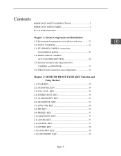
... and Installation 1-1) Environmental requirements for installation and safety .......... 21 E 1-2) System Components 22 1-3) STANDARD CAMERA composition and installation method 23 1-4) NIGHTVISION CAMERA (SOC-N120 INTRODUCTION 28 1-5) External terminal connecting method for CAMERA and MONITOR 31 1-6) Whole System connection and configuration 32 Chapter 2: MONITOR FRONT PANEL KEY Function and Using Method 2-1) TALK KEY 35 2-2) AUD/SP SEL...
... and Installation 1-1) Environmental requirements for installation and safety .......... 21 E 1-2) System Components 22 1-3) STANDARD CAMERA composition and installation method 23 1-4) NIGHTVISION CAMERA (SOC-N120 INTRODUCTION 28 1-5) External terminal connecting method for CAMERA and MONITOR 31 1-6) Whole System connection and configuration 32 Chapter 2: MONITOR FRONT PANEL KEY Function and Using Method 2-1) TALK KEY 35 2-2) AUD/SP SEL...
User Guide
Page 20
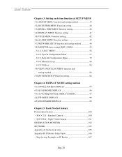
...setting 41 3-5) TITLE MENU Function setting 42 3-6) ALARM MENU Function setting 43 3-7) NETWORK SETUP function and setting method 44 3-8) MONITOR basic setting(SMO-152QN 52 3-8-1) "LIVE" MENU 54 3-8-2) System Configuration Menu 67 3-8-3) Network Configuration Menu 75 3-8-4) Moniter Set up 84 3-8-5) Utilities...ZOOM MODE DISPLAY 99 Chapter 5: Each Product feature Product Specification 100 • SOC-C120 : Standard Camera 100 • SOC-N120 : Night Vision Camera 101 OBSERVATION MONITOR 102 NETWORK 103 Appendix A) Software up data 105 Appendix B) IP Router Setup Guide 106 •...
...setting 41 3-5) TITLE MENU Function setting 42 3-6) ALARM MENU Function setting 43 3-7) NETWORK SETUP function and setting method 44 3-8) MONITOR basic setting(SMO-152QN 52 3-8-1) "LIVE" MENU 54 3-8-2) System Configuration Menu 67 3-8-3) Network Configuration Menu 75 3-8-4) Moniter Set up 84 3-8-5) Utilities...ZOOM MODE DISPLAY 99 Chapter 5: Each Product feature Product Specification 100 • SOC-C120 : Standard Camera 100 • SOC-N120 : Night Vision Camera 101 OBSERVATION MONITOR 102 NETWORK 103 Appendix A) Software up data 105 Appendix B) IP Router Setup Guide 106 •...
User Guide
Page 22
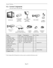
... OUT CABLE POWER CODE & INSTALLATION MANUAL CAMERA CABLE SENSOR ETHERNET CONNECTOR CABLE ITEM MONITOR STANDARD CAMERA NIGHT VISION CAMERA CAMERA BRACKET CAMERA CABLE INSTALLATION MANUAL POWER CORD VCR CABLE VIDEO OUT CABLE SENSOR CONNECTOR ETHERNET CABLE MODEL DESCRIPTION Q'ty SMO-152QN 15" FLAT CRT MONITOR 1 SOC-C120 NORMAL TYPE CAMERA 2 SOC-N120 NORMAL TYPE CAMERA 2 SBR-110S STAND TYPE BRACKET 4 MCB...
... OUT CABLE POWER CODE & INSTALLATION MANUAL CAMERA CABLE SENSOR ETHERNET CONNECTOR CABLE ITEM MONITOR STANDARD CAMERA NIGHT VISION CAMERA CAMERA BRACKET CAMERA CABLE INSTALLATION MANUAL POWER CORD VCR CABLE VIDEO OUT CABLE SENSOR CONNECTOR ETHERNET CABLE MODEL DESCRIPTION Q'ty SMO-152QN 15" FLAT CRT MONITOR 1 SOC-C120 NORMAL TYPE CAMERA 2 SOC-N120 NORMAL TYPE CAMERA 2 SBR-110S STAND TYPE BRACKET 4 MCB...
User Guide
Page 23
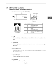
... the vicinity of 3.8mm and makes it either above or below the camera if necessary. Lens It has a focal length of the camera location and transmitting to the camera. c. Camera fitting groove Enables the camera to the monitor. 1-3) STANDARD CAMERA composition and installation method 1) Standard Camera composition (SOC-C120) E PIN NUMBER ! @ # $ % ^ SPEC SPEAKER(HOT) VIDEO_OUT GND SPEAKER(COLD...
... the vicinity of 3.8mm and makes it either above or below the camera if necessary. Lens It has a focal length of the camera location and transmitting to the camera. c. Camera fitting groove Enables the camera to the monitor. 1-3) STANDARD CAMERA composition and installation method 1) Standard Camera composition (SOC-C120) E PIN NUMBER ! @ # $ % ^ SPEC SPEAKER(HOT) VIDEO_OUT GND SPEAKER(COLD...

User Guide
Page 24
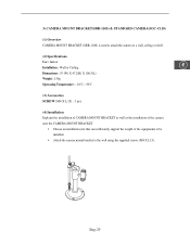
Adjust the camera to the wall or ceiling using the camera mount bracket (SBR-110S). Attach the camera mount bracket to target the video location and tighten the bracket handle on the camera mount bracket. 4x15 sized screws wall or ceiling Eng-24 Choose an installation site that can be installed. Speaker It outputs the sound signal which was transfered from the monitor. 2) INSTALLING STANDARD CAMERA (SOC-C120) SOC-C120 camera can sufficiently support the weight of the equipments to be attached to the wall, ceiling or shelf using the supplied three screws (M4 X L15). f.
Adjust the camera to the wall or ceiling using the camera mount bracket (SBR-110S). Attach the camera mount bracket to target the video location and tighten the bracket handle on the camera mount bracket. 4x15 sized screws wall or ceiling Eng-24 Choose an installation site that can be installed. Speaker It outputs the sound signal which was transfered from the monitor. 2) INSTALLING STANDARD CAMERA (SOC-C120) SOC-C120 camera can sufficiently support the weight of the equipments to be attached to the wall, ceiling or shelf using the supplied three screws (M4 X L15). f.
User Guide
Page 25
....2(H) X 100.5(L) Weight : 150g Operating Temperature : -10°C ~ 50°C (3) Accessories SCREW (M4 X L15) : 3 pcs (4) Installation Explains the installation of CAMERA MOUNT BRACKET as wall as the installation of the camera onto the CAMERA MOUNT BRACKET. • Choose an installation site that can sufficiently support the weight of the equipments to be installed. •...
....2(H) X 100.5(L) Weight : 150g Operating Temperature : -10°C ~ 50°C (3) Accessories SCREW (M4 X L15) : 3 pcs (4) Installation Explains the installation of CAMERA MOUNT BRACKET as wall as the installation of the camera onto the CAMERA MOUNT BRACKET. • Choose an installation site that can sufficiently support the weight of the equipments to be installed. •...

User Guide
Page 26
Tighten the handle, turning it clockwise, and lock the camera in position. • Connect the camera cable to the male screw of the Camera Mount Bracket by rotating the camera in clockwise. • Loosen the handle by turning it in a counter clockwise direction and then adjust the camera position . SOC-C120 Handle Eng-26 • Adjust the camera to target the video location and tighten the bracket handle on to the camera. Install the camera on the camera mount bracket.
Tighten the handle, turning it clockwise, and lock the camera in position. • Connect the camera cable to the male screw of the Camera Mount Bracket by rotating the camera in clockwise. • Loosen the handle by turning it in a counter clockwise direction and then adjust the camera position . SOC-C120 Handle Eng-26 • Adjust the camera to target the video location and tighten the bracket handle on to the camera. Install the camera on the camera mount bracket.
User Guide
Page 27
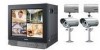
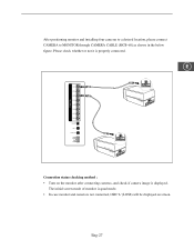
The initial screen mode of monitor is quad mode. • In case monitor and camera is displayed. E SOC-C120 VIDEO OUT SOC-C120 Connection status checking method : • Turn on the monitor after connecting cameras, and check if camera image is not connected, OSD 'L'(LOSS) will be displayed on screen. Eng-27 After positioning monitor and installing four cameras to a desired location, please connect CAMERA to MONITOR through CAMERA CABLE (MCB-60) as shown in the below figure. Please check whether or not it is properly connected.
The initial screen mode of monitor is quad mode. • In case monitor and camera is displayed. E SOC-C120 VIDEO OUT SOC-C120 Connection status checking method : • Turn on the monitor after connecting cameras, and check if camera image is not connected, OSD 'L'(LOSS) will be displayed on screen. Eng-27 After positioning monitor and installing four cameras to a desired location, please connect CAMERA to MONITOR through CAMERA CABLE (MCB-60) as shown in the below figure. Please check whether or not it is properly connected.
User Guide
Page 28
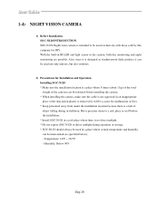
...-in IR LED and light sensor in stallation. Temperature: 14°F ~ 122°F - 1-4) NIGHT VISION CAMERA 1) Before Installation SOC-N120 INTRODUCTION SOC-N120 Nightvision camera is intended to direct sunlight during in the camera, both day monitoring and night monitoring are possible. Humidity: Below 90% Eng-28 Move precious items to a safe place as well...
...-in IR LED and light sensor in stallation. Temperature: 14°F ~ 122°F - 1-4) NIGHT VISION CAMERA 1) Before Installation SOC-N120 INTRODUCTION SOC-N120 Nightvision camera is intended to direct sunlight during in the camera, both day monitoring and night monitoring are possible. Humidity: Below 90% Eng-28 Move precious items to a safe place as well...
User Guide
Page 29
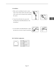
Make sure the installation location is a place where 5 times (about 2.2lbs) of the total weight of the camera can be tolerated before installing the camera. 2. Use the handle on the Mount Bracket to adjust the direction you want to the desired place. 3. SOC-N120 Pin Configuration 1 SP2 VIDEO_OUT 3 GND 4 SP+ 5 ALM/AUDIO 6 VDD Eng-29 3) Installation 1. Connect the cable below the camera after E attaching the provided Mount Bracket to setup for monitoring.
Make sure the installation location is a place where 5 times (about 2.2lbs) of the total weight of the camera can be tolerated before installing the camera. 2. Use the handle on the Mount Bracket to adjust the direction you want to the desired place. 3. SOC-N120 Pin Configuration 1 SP2 VIDEO_OUT 3 GND 4 SP+ 5 ALM/AUDIO 6 VDD Eng-29 3) Installation 1. Connect the cable below the camera after E attaching the provided Mount Bracket to setup for monitoring.
User Guide
Page 30
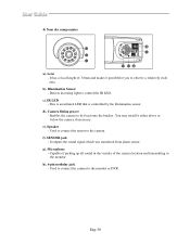
...a relatively wide area. This is an infrared LED that is controlled by the illumination sensor. Enables the camera to the monitor or DVR. You may install it possiblefor you to the monitor. f). Capable of picking up all sound in the vicinity of 3.8mm and makes it either above or... below the camera if necessary. c). d). Speaker - Microphone - Used to connect the camera to be fixed onto the bracket. Detects incoming light to the camera. e). Used to connect...
...a relatively wide area. This is an infrared LED that is controlled by the illumination sensor. Enables the camera to the monitor or DVR. You may install it possiblefor you to the monitor. f). Capable of picking up all sound in the vicinity of 3.8mm and makes it either above or... below the camera if necessary. c). d). Speaker - Microphone - Used to connect the camera to be fixed onto the bracket. Detects incoming light to the camera. e). Used to connect...
User Guide
Page 31
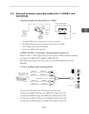
d) Connect the AUDIO OUT plug to THROUGH OUT. Eng-31 1-5) External terminal connecting method for CAMERA and MONITOR 1) External terminal connecting method for CAMERA Camera alarm injack PIR Sensor Sensor in put E Sensor • An additional PIR sensor or external sensor can also be ... supplied. (Sold separately) 2) VIDEO OUT BNC (1~4) terminals connecting method of monitor rear VIDEO OUT BNC1 ~ BNC4 terminals in the rear of the monitor are VIDEO terminals for outputting video images from OBSEVATION CAMERA to the AUDIO IN terminal of the VCR. BNC VIDEO output terminal can ...
d) Connect the AUDIO OUT plug to THROUGH OUT. Eng-31 1-5) External terminal connecting method for CAMERA and MONITOR 1) External terminal connecting method for CAMERA Camera alarm injack PIR Sensor Sensor in put E Sensor • An additional PIR sensor or external sensor can also be ... supplied. (Sold separately) 2) VIDEO OUT BNC (1~4) terminals connecting method of monitor rear VIDEO OUT BNC1 ~ BNC4 terminals in the rear of the monitor are VIDEO terminals for outputting video images from OBSEVATION CAMERA to the AUDIO IN terminal of the VCR. BNC VIDEO output terminal can ...
User Guide
Page 34
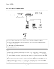
you must go through the Port Forwarding portion of the setup. Turn on the MONITOR power. Notice If you must set up , you must use (such as a PC and a SMO-152QN or several SMO-152QN); and you must use during setup. 3. Eng-34 If you are using an existing Router which is highly ... to MONITOR. 4. you may not need to do the setup. Connect LAN cable of Local PC to use an IP Router (different from a simple Network Hub); Connect Video cable of Camera to WAN port of the Router agian, but have more than one internet device to work with the SMO-152QN; Connect...
you must go through the Port Forwarding portion of the setup. Turn on the MONITOR power. Notice If you must set up , you must use (such as a PC and a SMO-152QN or several SMO-152QN); and you must use during setup. 3. Eng-34 If you are using an existing Router which is highly ... to MONITOR. 4. you may not need to do the setup. Connect LAN cable of Local PC to use an IP Router (different from a simple Network Hub); Connect Video cable of Camera to WAN port of the Router agian, but have more than one internet device to work with the SMO-152QN; Connect...
User Guide
Page 35
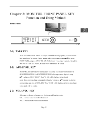
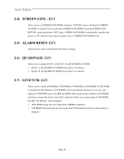
...MIC in the front of the monitor. If you want to exchange voice signals with another camera, use L/M key again to exchange voice signals with the monitor at QUAD DISPLAY MODE. At this function, select a target camera with the monitor. 2-3) VOL+/VOL- KEY Allows users to intended camera by using L/M , and ... with the TALK KEY pressed, the signal will be transmitted to the camera. 2-2) AUD/SP SEL KEY AUD/SP SEL KEY allows users to select a camera to select the camera display, and press AUD/SEL KEY. Chapter 2: MONITOR FRONT PANEL KEY Function and Using Method Front Panel E 2-1) TALK KEY...
...MIC in the front of the monitor. If you want to exchange voice signals with another camera, use L/M key again to exchange voice signals with the monitor at QUAD DISPLAY MODE. At this function, select a target camera with the monitor. 2-3) VOL+/VOL- KEY Allows users to intended camera by using L/M , and ... with the TALK KEY pressed, the signal will be transmitted to the camera. 2-2) AUD/SP SEL KEY AUD/SP SEL KEY allows users to select a camera to select the camera display, and press AUD/SEL KEY. Chapter 2: MONITOR FRONT PANEL KEY Function and Using Method Front Panel E 2-1) TALK KEY...
User Guide
Page 36
...OSD "NO SIGNAL" will be displayed. • LIVE MODE: Image and voice signal from CAMERA is cancelled, the QUAD picture of LIVE MODE will be automatically displayed. B: QUAD DISPLAY MODE from the rear of monitor. In case any event happens at VCR MODE such as an alarm or loss at SCREEN... SAVE MODE occurs. 2-5) ALARM RESET- SCREEN SAVE MODE is automatically cancelled and picture is working. 2-6) QUAD/PAGE- KEY Alarm function can exit from Camera 1 to Camera 4 • QUAD - KEY...
...OSD "NO SIGNAL" will be displayed. • LIVE MODE: Image and voice signal from CAMERA is cancelled, the QUAD picture of LIVE MODE will be automatically displayed. B: QUAD DISPLAY MODE from the rear of monitor. In case any event happens at VCR MODE such as an alarm or loss at SCREEN... SAVE MODE occurs. 2-5) ALARM RESET- SCREEN SAVE MODE is automatically cancelled and picture is working. 2-6) QUAD/PAGE- KEY Alarm function can exit from Camera 1 to Camera 4 • QUAD - KEY...
User Guide
Page 37
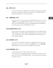
...2-12) POWER- KEY It turns ON/OFF the power of the monitor and camera at PAUSE MODE. In case the monitor power is ON, LED of SETUP MENU, and switch the picture automatically... during the DWELL TIME pre-set sequence. KEY E This key allows users to see a target camera picture at the same time. The main screen can move to another channel while PIP is displayed in...a while, the OSD "SYSTEM INITIALIZED..." 2-8) PIP- KEY Can be displayed on pause picture from the camera. DISPLAY MODE setting method(Eng-95)" for details of a picture doubling it in color bar pattern. Other...
...2-12) POWER- KEY It turns ON/OFF the power of the monitor and camera at PAUSE MODE. In case the monitor power is ON, LED of SETUP MENU, and switch the picture automatically... during the DWELL TIME pre-set sequence. KEY E This key allows users to see a target camera picture at the same time. The main screen can move to another channel while PIP is displayed in...a while, the OSD "SYSTEM INITIALIZED..." 2-8) PIP- KEY Can be displayed on pause picture from the camera. DISPLAY MODE setting method(Eng-95)" for details of a picture doubling it in color bar pattern. Other...

User Guide
Page 38
2-13) ENTER- KEY Enter key allows users to 1.Enter set up menu movement and setting mode 2.Display single camera picture 2-14) UP/DOWN KEY Allows users to 1.Change camera channel 2.Select set up menu movement and setting mode UP: Increase items DOWN: Decrease items 2-15) LEFT/RIGHT KEY Allows users to set date LEFT: Decrease Date RIGHT: Increase Date Eng-38
2-13) ENTER- KEY Enter key allows users to 1.Enter set up menu movement and setting mode 2.Display single camera picture 2-14) UP/DOWN KEY Allows users to 1.Change camera channel 2.Select set up menu movement and setting mode UP: Increase items DOWN: Decrease items 2-15) LEFT/RIGHT KEY Allows users to set date LEFT: Decrease Date RIGHT: Increase Date Eng-38

User Guide
Page 41
...to 3-7) NETWORK SETTING function and setting method (Eng-44) for the set value. 1) BORDER item determines whether or not boarder line is set for each camera channel by using L/M KEY, and using L/M KEY, each item by using ➛/❿ KEY set time and switched to the next picture automatically. 3-4) DISPLAY....) 06/01/03 DISPLAY SETTING BORDER BORDER COLOR PIP POSITION NETWORK STATUS 13:14:00 ON GRAY B-RIGHT ON/OFF Move to each camera picture will be displayed for the respective detailed status. (ON: Displays the NETWORK STATUS, OFF: Does not display the NETWORK STATUS) Eng-41...
...to 3-7) NETWORK SETTING function and setting method (Eng-44) for the set value. 1) BORDER item determines whether or not boarder line is set for each camera channel by using L/M KEY, and using L/M KEY, each item by using ➛/❿ KEY set time and switched to the next picture automatically. 3-4) DISPLAY....) 06/01/03 DISPLAY SETTING BORDER BORDER COLOR PIP POSITION NETWORK STATUS 13:14:00 ON GRAY B-RIGHT ON/OFF Move to each camera picture will be displayed for the respective detailed status. (ON: Displays the NETWORK STATUS, OFF: Does not display the NETWORK STATUS) Eng-41...

User Guide
Page 42
... CAM2 CAM3 CAM4 CAM5 CAM6 CAM7 CAM8 01 2345678 9: = . ( ) A B C D E F G H I J K L M N O P QR STUVWXYZ[/]_ + − Move to a target camera channel by using L/M KEY, then press the ENTER KEY to the next space for a camera title.) Eng-42 3-5) TITLE MENU Function setting • Function: Set the title of each... camera at the space of the first character of camera title. Move the cursor to #5. The cursor automatically moves to set ....
... CAM2 CAM3 CAM4 CAM5 CAM6 CAM7 CAM8 01 2345678 9: = . ( ) A B C D E F G H I J K L M N O P QR STUVWXYZ[/]_ + − Move to a target camera channel by using L/M KEY, then press the ENTER KEY to the next space for a camera title.) Eng-42 3-5) TITLE MENU Function setting • Function: Set the title of each... camera at the space of the first character of camera title. Move the cursor to #5. The cursor automatically moves to set ....
User Guide
Page 43
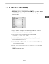
...OFF TIME item sets beginning time (ON) and end time (OFF) that monitor recognizes alarm operation as alarm event. * Note :Even if CAMERA ALARM is set to #6. 3-6) ALARM MENU Function setting • Function: Allows users to set in monitor is used at time band except pre-set ALARM ON/OFF TIME. (4) ...BUZZER item sets whether or not buzzer device set the ALARM MODE for each camera. • Setting method: Move to ON, alarm operation is not carried at...
...OFF TIME item sets beginning time (ON) and end time (OFF) that monitor recognizes alarm operation as alarm event. * Note :Even if CAMERA ALARM is set to #6. 3-6) ALARM MENU Function setting • Function: Allows users to set in monitor is used at time band except pre-set ALARM ON/OFF TIME. (4) ...BUZZER item sets whether or not buzzer device set the ALARM MODE for each camera. • Setting method: Move to ON, alarm operation is not carried at...
