User Manual (user Manual) (ver.1.0) (English)
Page 1
All rights reserved. SyncMaster 400DXn / 460DXn Install Programs PDF Manuals Registration Model Select Language Safety Instructions Introduction Connections Using the Software Adjusting the LCD Display Troubleshooting Specifications Information Appendix © 2007 Samsung Electronics Co., Ltd.
All rights reserved. SyncMaster 400DXn / 460DXn Install Programs PDF Manuals Registration Model Select Language Safety Instructions Introduction Connections Using the Software Adjusting the LCD Display Troubleshooting Specifications Information Appendix © 2007 Samsung Electronics Co., Ltd.
User Manual (user Manual) (ver.1.0) (English)
Page 2
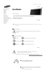
... they are not applicable in bodily harm or damage to the user. Select Language Main Page Model Safety Instructions Notational Power Installation Clean Others Introduction Connections Using the Software Adjusting the LCD Display Troubleshooting Specifications Information Appendix The color and appearance of the product may vary depending on the model, and...
... they are not applicable in bodily harm or damage to the user. Select Language Main Page Model Safety Instructions Notational Power Installation Clean Others Introduction Connections Using the Software Adjusting the LCD Display Troubleshooting Specifications Information Appendix The color and appearance of the product may vary depending on the model, and...
User Manual (user Manual) (ver.1.0) (English)
Page 3
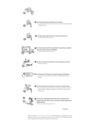
.... z An improper ground may cause electric shock or fire. z If the connector or plug of the power cord is dusty. z This may cause fire. z A bad connection may cause electric shock or fire. Do not use the power cord when the connector or plug is dusty, clean it with a dry cloth. Installation... damage.(Class l Equipment only.) Insert the power plug firmly so that it operates for 24 hours such as at airports, train stations etc. Do not connect too many extension cords or plugs to chemical substances and where it does not come loose. z Using the power cord with heavy dust, high or...
.... z An improper ground may cause electric shock or fire. z If the connector or plug of the power cord is dusty. z This may cause fire. z A bad connection may cause electric shock or fire. Do not use the power cord when the connector or plug is dusty, clean it with a dry cloth. Installation... damage.(Class l Equipment only.) Insert the power plug firmly so that it operates for 24 hours such as at airports, train stations etc. Do not connect too many extension cords or plugs to chemical substances and where it does not come loose. z Using the power cord with heavy dust, high or...
User Manual (user Manual) (ver.1.0) (English)
Page 8
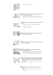
... power cord. z Change the mode to energy saving mode or set a screensaver to vibrations. Make sure that all cables, including the antenna cable and cables connected to the person carrying it . Do not install the product on an unstable, uneven surface or a location prone to a changing picture when away from the...
... power cord. z Change the mode to energy saving mode or set a screensaver to vibrations. Make sure that all cables, including the antenna cable and cables connected to the person carrying it . Do not install the product on an unstable, uneven surface or a location prone to a changing picture when away from the...
User Manual (user Manual) (ver.1.0) (English)
Page 11
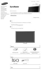
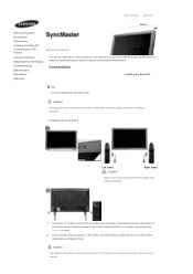
... Power Cord If any items are included with your dealer. Select Language Main Page Model Safety Instructions Introduction Package Contents Your LCD Display Machanical Layout Connections Using the Software Adjusting the LCD Display Troubleshooting Specifications Information Appendix The color and appearance of performance enhancement. Contact a local dealer to buy optional items...
... Power Cord If any items are included with your dealer. Select Language Main Page Model Safety Instructions Introduction Package Contents Your LCD Display Machanical Layout Connections Using the Software Adjusting the LCD Display Troubleshooting Specifications Information Appendix The color and appearance of performance enhancement. Contact a local dealer to buy optional items...
User Manual (user Manual) (ver.1.0) (English)
Page 13
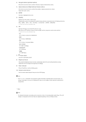
...the source is not needed or when leaving it unattended for further information regarding power saving functions. Rear Note • For detailed information concerning cable connections, refer to Video mode. Adjusts the audio volume. 4) ENTER Activates a highlighted menu item. 5) SOURCE Switches from one PIP cannot overlap on... clip. 6) PIP Push the PIP button to turn your LCD Display OFF when it is only allowed for external devices that are connected to the LCD Display at the back may vary slightly depending on the LCD Display. More than one menu item to another vertically ...
...the source is not needed or when leaving it unattended for further information regarding power saving functions. Rear Note • For detailed information concerning cable connections, refer to Video mode. Adjusts the audio volume. 4) ENTER Activates a highlighted menu item. 5) SOURCE Switches from one PIP cannot overlap on... clip. 6) PIP Push the PIP button to turn your LCD Display OFF when it is only allowed for external devices that are connected to the LCD Display at the back may vary slightly depending on the LCD Display. More than one menu item to another vertically ...

User Manual (user Manual) (ver.1.0) (English)
Page 14
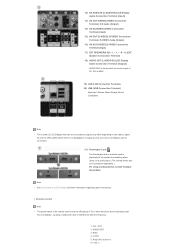
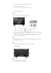
.../Off. 2) POWER IN The power cord plugs into the LCD Display and the wall plug. 3) REMOTE OUT/IN You can use a wired remote control by connecting it to your monitor. 4) RS232C OUT/IN (RS232C Serial PORT) MDC(Multiple Display Control) Program Port 5) DVI / PC / HDMI IN [PC/DVI/BNC ...AUDIO IN] (PC/DVI/BNC/HDMI Audio Connection Terminal (Input)) 6) DVI / PC / HDMI IN [HDMI] Connect the HDMI terminal at the back of your monitor to DVI-D) - DVI mode (Digital PC) 9) COMPONENT AUDIO IN [L-AUDIO-R] (Component Audio...
.../Off. 2) POWER IN The power cord plugs into the LCD Display and the wall plug. 3) REMOTE OUT/IN You can use a wired remote control by connecting it to your monitor. 4) RS232C OUT/IN (RS232C Serial PORT) MDC(Multiple Display Control) Program Port 5) DVI / PC / HDMI IN [PC/DVI/BNC ...AUDIO IN] (PC/DVI/BNC/HDMI Audio Connection Terminal (Input)) 6) DVI / PC / HDMI IN [HDMI] Connect the HDMI terminal at the back of your monitor to DVI-D) - DVI mode (Digital PC) 9) COMPONENT AUDIO IN [L-AUDIO-R] (Component Audio...
User Manual (user Manual) (ver.1.0) (English)
Page 15
... the frequency. 1. MagicNet buttons 6.+100 -/-- ON / OFF 2. MDC 4. LOCK 5. L - +, - - MAGICNET 3. R - +] (EXT Speaker Connection Terminal) 18) AUDIO OUT [L-AUDIO-R] (LCD Display Audio Connection Terminal (Output)) AUDIO OUT is a device used to physically fix the system to something when using it in a public place. (The... locking device has to be connected to loopout may be affected by a TV or other electronic device operating near the LCD Display , causing a malfunction due to ten...
... the frequency. 1. MagicNet buttons 6.+100 -/-- ON / OFF 2. MDC 4. LOCK 5. L - +, - - MAGICNET 3. R - +] (EXT Speaker Connection Terminal) 18) AUDIO OUT [L-AUDIO-R] (LCD Display Audio Connection Terminal (Output)) AUDIO OUT is a device used to physically fix the system to something when using it in a public place. (The... locking device has to be connected to loopout may be affected by a TV or other electronic device operating near the LCD Display , causing a malfunction due to ten...
User Manual (user Manual) (ver.1.0) (English)
Page 33
... KIT Note • Only the supplied bolts should be responsible for damages caused by using a base other than those specified. Caution Samsung Electronics will not be used. If you install a wall mount kit for your product, a Cover Hole is inserted. Installing the ...it. 2) Insert it into the marked place and fasten it firmly. Select Language Main Page Model Safety Instructions Introduction Connections Installing the Stand KIT Connecting the LCD Display Using the Software Adjusting the LCD Display Troubleshooting Specifications Information Appendix The color and appearance of the ...
... KIT Note • Only the supplied bolts should be responsible for damages caused by using a base other than those specified. Caution Samsung Electronics will not be used. If you install a wall mount kit for your product, a Cover Hole is inserted. Installing the ...it. 2) Insert it into the marked place and fasten it firmly. Select Language Main Page Model Safety Instructions Introduction Connections Installing the Stand KIT Connecting the LCD Display Using the Software Adjusting the LCD Display Troubleshooting Specifications Information Appendix The color and appearance of the ...

User Manual (user Manual) (ver.1.0) (English)
Page 34
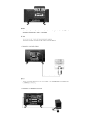
Note • AV input devices such as DVD players, VCR's or camcorders as well as your computer can be connected to the BNC/COMPONENT IN - Connecting a Computer 1) Connect the power cord for your LCD Display to the power port on the back of the following: 2-1) Using the D-sub (Analog) connector on the video ...card. Choose one of the LCD Display. Connect the D-sub to wire the earth lead in advance. Connect the BNC Cable to the LCD Display. Make sure to the 15-pin, RGB port on the back of your LCD...
Note • AV input devices such as DVD players, VCR's or camcorders as well as your computer can be connected to the BNC/COMPONENT IN - Connecting a Computer 1) Connect the power cord for your LCD Display to the power port on the back of the following: 2-1) Using the D-sub (Analog) connector on the video ...card. Choose one of the LCD Display. Connect the D-sub to wire the earth lead in advance. Connect the BNC Cable to the LCD Display. Make sure to the 15-pin, RGB port on the back of your LCD...

User Manual (user Manual) (ver.1.0) (English)
Page 35
... computer and the LCD Display. Note • The S-VHS or BNC cable is optional. Contact a local Samsung Electronics Service Center to buy optional items. Connecting a VCR 1) AV input devices such as VCRs or Camcorders are connected via the AV IN [VIDEO] or AV IN [S-VIDEO] of the LCD Display using an S-VHS or... BNC cable. 2) Connect the Audio (L) and Audio (R) terminals of a VCR or Camcorders to the audio port on the back of the LCD Display or on the remote control. &#...
... computer and the LCD Display. Note • The S-VHS or BNC cable is optional. Contact a local Samsung Electronics Service Center to buy optional items. Connecting a VCR 1) AV input devices such as VCRs or Camcorders are connected via the AV IN [VIDEO] or AV IN [S-VIDEO] of the LCD Display using an S-VHS or... BNC cable. 2) Connect the Audio (L) and Audio (R) terminals of a VCR or Camcorders to the audio port on the back of the LCD Display or on the remote control. &#...

User Manual (user Manual) (ver.1.0) (English)
Page 36
...the LCD Display or on the remote control. • Then, start the Camcorders with a DVD disc inserted. Note • Select AV for the connection to a DVD player using the SOURCE button on the front of the LCD Display or on the remote control. • Then, start the DVD ...camcorder. For an explanation of Component video, consult your DVD manual. Note They are usually found on the DVD player. Connecting a Camcorder 1) Locate the A/V output jacks on the camcorder. Connect a set of audio cables between the COMPONENT AUDIO IN [L-AUDIO-R] on the LCD Display and the AUDIO OUT jacks ...
...the LCD Display or on the remote control. • Then, start the Camcorders with a DVD disc inserted. Note • Select AV for the connection to a DVD player using the SOURCE button on the front of the LCD Display or on the remote control. • Then, start the DVD ...camcorder. For an explanation of Component video, consult your DVD manual. Note They are usually found on the DVD player. Connecting a Camcorder 1) Locate the A/V output jacks on the camcorder. Connect a set of audio cables between the COMPONENT AUDIO IN [L-AUDIO-R] on the LCD Display and the AUDIO OUT jacks ...
User Manual (user Manual) (ver.1.0) (English)
Page 37
PR, Y, PB port on the LCD Display and the PR, Y, PB jacks on the Set Top Box. 2) Connect a set of two cables. Connecting a DTV Set Top Box Note • The connections for the connection to connect a set without the speaker stand. Note • Select Component for a typical Set Top Box are usually included with....) If your Set Top Box owner's manual. Note • For an explanation of the LCD Display or on the Set Top Box. Connecting Speakers Note • Fasten the SET and the speaker using the SOURCE button on the front of Component video, see your camcorder is stereo...
PR, Y, PB port on the LCD Display and the PR, Y, PB jacks on the Set Top Box. 2) Connect a set of two cables. Connecting a DTV Set Top Box Note • The connections for the connection to connect a set without the speaker stand. Note • Select Component for a typical Set Top Box are usually included with....) If your Set Top Box owner's manual. Note • For an explanation of the LCD Display or on the Set Top Box. Connecting Speakers Note • Fasten the SET and the speaker using the SOURCE button on the front of Component video, see your camcorder is stereo...
User Manual (user Manual) (ver.1.0) (English)
Page 38
Connecting to an Audio System Note • Connect a set of audio cables between the speaker connection jack on the back of the speaker. Connecting to a Wired Remote Control The speaker-bracket for connecting the SET speaker my become damaged. Note • Do not move the SET while the SET is connected to the speakers. Note • Connect the speaker connection cable between the AUX L, R jacks on the AUDIO SYSTEM and the AUDIO OUT [L-AUDIO-R] on the back of the SET and the speaker connection jack on LCD Display.
Connecting to an Audio System Note • Connect a set of audio cables between the speaker connection jack on the back of the speaker. Connecting to a Wired Remote Control The speaker-bracket for connecting the SET speaker my become damaged. Note • Do not move the SET while the SET is connected to the speakers. Note • Connect the speaker connection cable between the AUX L, R jacks on the AUDIO SYSTEM and the AUDIO OUT [L-AUDIO-R] on the back of the SET and the speaker connection jack on LCD Display.

User Manual (user Manual) (ver.1.0) (English)
Page 39
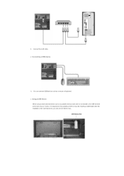
...the HDMI IN terminal of the monitor using a DVI to HDMI cable. 2) Connect the red and white jacks of an RCA to stereo (for PC) cable to the same colored audio output terminals of the digital output device, and connect the opposite jack to the HDMI / PC / DVI-D AUDIO IN terminal ...of the monitor. Connecting a LAN Cable Connecting Using a DVI to HDMI Cable 1) Connect the DVI output terminal of a digital output device to the HDMI IN terminal of...
...the HDMI IN terminal of the monitor using a DVI to HDMI cable. 2) Connect the red and white jacks of an RCA to stereo (for PC) cable to the same colored audio output terminals of the digital output device, and connect the opposite jack to the HDMI / PC / DVI-D AUDIO IN terminal ...of the monitor. Connecting a LAN Cable Connecting Using a DVI to HDMI Cable 1) Connect the DVI output terminal of a digital output device to the HDMI IN terminal of...
User Manual (user Manual) (ver.1.0) (English)
Page 40
By installing a USB holder after the installation of an external device, you can connect USB devices such as a portable memory stick and it is connected to the USB terminal at the back of your monitor, it is exposed to the possiblity of theft or loss. Using a USB Holder When using a small external device such as a mouse or keyboard. Connecting a USB device 1) You can prevent theft or loss. 1) Connect the LAN cable.
By installing a USB holder after the installation of an external device, you can connect USB devices such as a portable memory stick and it is connected to the USB terminal at the back of your monitor, it is exposed to the possiblity of theft or loss. Using a USB Holder When using a small external device such as a mouse or keyboard. Connecting a USB device 1) You can prevent theft or loss. 1) Connect the LAN cable.
User Manual (user Manual) (ver.1.0) (English)
Page 43
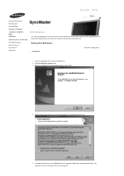
Select Language Main Page Model Safety Instructions Introduction Connections Using the Software Installation MagicNet MDC MagicNet Adjusting the LCD Display Troubleshooting Specifications Information Appendix The color and appearance of the product may vary depending ...
Select Language Main Page Model Safety Instructions Introduction Connections Using the Software Installation MagicNet MDC MagicNet Adjusting the LCD Display Troubleshooting Specifications Information Appendix The color and appearance of the product may vary depending ...

User Manual (user Manual) (ver.1.0) (English)
Page 46
...the network status. 4. What is MagicNet? | Using MagicNet | Remote Management | Message | What is enabled, the monitor attempts to connect to other servers and connects to identify itself on them . Library Option | Screen | | Client / Contents | Server Schedule Troubleshooting MagicNet uses an Ethernet network...screens to your circumstances. Network/Local Schedules and Publishing → You can only be displayed on the screens according to be connected if they have the same server name. A server and a monitor can transfer the edited screens to a single monitor....
...the network status. 4. What is MagicNet? | Using MagicNet | Remote Management | Message | What is enabled, the monitor attempts to connect to other servers and connects to identify itself on them . Library Option | Screen | | Client / Contents | Server Schedule Troubleshooting MagicNet uses an Ethernet network...screens to your circumstances. Network/Local Schedules and Publishing → You can only be displayed on the screens according to be connected if they have the same server name. A server and a monitor can transfer the edited screens to a single monitor....

User Manual (user Manual) (ver.1.0) (English)
Page 47
Update and PXE → The Update function allows you to connect to easily update the programs on selected monitors regardless of schedules. 6. VNC → The VNC function allows you to a monitor remotely and view the status of , and diagnose monitors. 7. schedules. 5. The PXE allows you to recover the operating system image for a monitor. MDC and System → The MDC and System functions allow you to control, view the status of and control and diagnose it. 8. Instants message → You can display a message on the monitor.
Update and PXE → The Update function allows you to connect to easily update the programs on selected monitors regardless of schedules. 6. VNC → The VNC function allows you to a monitor remotely and view the status of , and diagnose monitors. 7. schedules. 5. The PXE allows you to recover the operating system image for a monitor. MDC and System → The MDC and System functions allow you to control, view the status of and control and diagnose it. 8. Instants message → You can display a message on the monitor.

User Manual (user Manual) (ver.1.0) (English)
Page 48
... user name and the password you set when installing the program. (For information on how to install MagicNet, refer to Installing MagicNet, Using the Software.) Connecting a Monitor to open the Server Setup window. What is MagicNet? | Using MagicNet | Remote Management | Message | Using MagicNet Library Option | Screen | | Client / Contents | Server Schedule Troubleshooting...
... user name and the password you set when installing the program. (For information on how to install MagicNet, refer to Installing MagicNet, Using the Software.) Connecting a Monitor to open the Server Setup window. What is MagicNet? | Using MagicNet | Remote Management | Message | Using MagicNet Library Option | Screen | | Client / Contents | Server Schedule Troubleshooting...

