
Service Manual
Page 1
Alignment and Adjustments 6. Disassembly and Reassembly 5. Exploded Views and Parts List 8. Operating Instructions 4. Specifications 3. Schematic Diagrams Troubleshooting 7. PCB Diagrams 9. Precaution 2. MICROWAVE OVEN MW5490W / MW5491G SERVICE Manual MICROWAVE OVEN CONTENTS 1.
Alignment and Adjustments 6. Disassembly and Reassembly 5. Exploded Views and Parts List 8. Operating Instructions 4. Specifications 3. Schematic Diagrams Troubleshooting 7. PCB Diagrams 9. Precaution 2. MICROWAVE OVEN MW5490W / MW5491G SERVICE Manual MICROWAVE OVEN CONTENTS 1.
Service Manual
Page 2
... hinges and latches, (5) evidence of dropping or abuse. (c) Before turning on microwave power for any service test or inspection within the microwave generating compartments, check the magnetron, wave guide or transmission line, and cavity for proper alignment, integrity, and connections. (d) Any defective or misadjusted components in the interlock, monitor, door seal, and microwave generation and transmission systems shall be repaired, replaced, or adjusted...
... hinges and latches, (5) evidence of dropping or abuse. (c) Before turning on microwave power for any service test or inspection within the microwave generating compartments, check the magnetron, wave guide or transmission line, and cavity for proper alignment, integrity, and connections. (d) Any defective or misadjusted components in the interlock, monitor, door seal, and microwave generation and transmission systems shall be repaired, replaced, or adjusted...
Service Manual
Page 3
... monitor switch. 12. Design Alteration Warning: Use exact replacement parts only, i.e., only those that the fuse has the correct rating for devices and radiological health immediatly. 4. This product complies with the door open : Instruct the user not to remove or reinstall any oven found to have emmission in accordance with the wiring diagram. If the fuse is especially important for the following at no cabinet openings...
... monitor switch. 12. Design Alteration Warning: Use exact replacement parts only, i.e., only those that the fuse has the correct rating for devices and radiological health immediatly. 4. This product complies with the door open : Instruct the user not to remove or reinstall any oven found to have emmission in accordance with the wiring diagram. If the fuse is especially important for the following at no cabinet openings...
Service Manual
Page 4
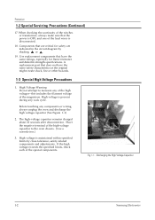
... cook cycle. Pretaution 1-2 Special Servicing Precautions (Continued) 17. High voltage is maintained within specified limits by shading, or . 19. Fig. 1-1. Discharging the High Voltage Capacitor 1-2 Samsung Electronics Use replacement components that does not have the same ratings, especially for safety are critical for flame resistance and dielectric strength specifications. Before touching any components or wiring, always unplug the oven...
... cook cycle. Pretaution 1-2 Special Servicing Precautions (Continued) 17. High voltage is maintained within specified limits by shading, or . 19. Fig. 1-1. Discharging the High Voltage Capacitor 1-2 Samsung Electronics Use replacement components that does not have the same ratings, especially for safety are critical for flame resistance and dielectric strength specifications. Before touching any components or wiring, always unplug the oven...
Service Manual
Page 5
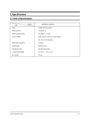
Specifications 2-1 Table of Specifications ITEM TIMER POWER SOURCE POWER CONSUMPTION OUTPUT POWER MODEL OPERATING FREQUENCY MAGNETRON COOLING METHOD OUTSIDE DIMENSIONS NET WEIGHT MW5490W / MW5491G 99 MINUTES 99 SECONDS 120V/60HZ, AC MICROWAVE : 1,450W FROM 100W TO 1000W (10 LEVEL POWER) (IEC-705 TEST PROCEDURE) 2,450MHz OM75PH(31)ESS COOLING FAN MOTOR 2011/32(W) x 1111/16(H) x 1411/16(D) 35.3 lbs. Samsung Electronics 2-1 2.
Specifications 2-1 Table of Specifications ITEM TIMER POWER SOURCE POWER CONSUMPTION OUTPUT POWER MODEL OPERATING FREQUENCY MAGNETRON COOLING METHOD OUTSIDE DIMENSIONS NET WEIGHT MW5490W / MW5491G 99 MINUTES 99 SECONDS 120V/60HZ, AC MICROWAVE : 1,450W FROM 100W TO 1000W (10 LEVEL POWER) (IEC-705 TEST PROCEDURE) 2,450MHz OM75PH(31)ESS COOLING FAN MOTOR 2011/32(W) x 1111/16(H) x 1411/16(D) 35.3 lbs. Samsung Electronics 2-1 2.
Service Manual
Page 6
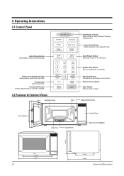
... Power Level Clock Pause Cancel 3 6 9 More/Less Kitchen Timer Start One Minute + Button Press once for every minute of food to start cooking 3-2 Features & External Views Door Ventilation Holes Light Safety Interlock Holes Door Latches Glass Tray Guide Roller Control Panel Open Door Push Button 297mm 3-1 370mm 517mm 215mm 379mm Samsung Electronics More/Less Button Inscreases to be defrosted. Kitchen Timer Button Start Button Press to be reheated. Operating Instructions 3-1 Control Panel Auto Defrost Button Sets weight of cooking at High power. Number Key Button Sets...
... Power Level Clock Pause Cancel 3 6 9 More/Less Kitchen Timer Start One Minute + Button Press once for every minute of food to start cooking 3-2 Features & External Views Door Ventilation Holes Light Safety Interlock Holes Door Latches Glass Tray Guide Roller Control Panel Open Door Push Button 297mm 3-1 370mm 517mm 215mm 379mm Samsung Electronics More/Less Button Inscreases to be defrosted. Kitchen Timer Button Start Button Press to be reheated. Operating Instructions 3-1 Control Panel Auto Defrost Button Sets weight of cooking at High power. Number Key Button Sets...
Service Manual
Page 7
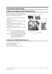
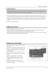
... all lead wires from the magnetron and lamp. 2. Disconnect all the leads. 3. Remove tow screws from hole of fan motor assembly. 6. Trans 4-2 Replacement of which are contained in good condition. Samsung Electronics 4-1 Remove the oven lamp by pulling out from the back panel of air cover. Discharge the high voltage capacitor. 2. Take out the fan motor assembly. 7. Remove the mounting bolts. 4. Disassembly and Reassembly 4-1 Replacement of Magnetron, Motor Assembly and Lamp Remove the magnetron including the shield...
... all lead wires from the magnetron and lamp. 2. Disconnect all the leads. 3. Remove tow screws from hole of fan motor assembly. 6. Trans 4-2 Replacement of which are contained in good condition. Samsung Electronics 4-1 Remove the oven lamp by pulling out from the back panel of air cover. Discharge the high voltage capacitor. 2. Take out the fan motor assembly. 7. Remove the mounting bolts. 4. Disassembly and Reassembly 4-1 Replacement of Magnetron, Motor Assembly and Lamp Remove the magnetron including the shield...
Service Manual
Page 8
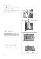
... door. 4-2 Door "E" Door "E" Key Door Spring Samsung Electronics Then remove the door assembly. Door "A" Door "C" 4-3-2 Removal of Door "E" Following the procedure as shown in the figure, insert and bend a thin metal plate between Door "E" and Door "A" until you hear the 'tick' sound. ¥ Insertion depth of the thin metal plate should be 0.5mm or less. 4-3-3 Removal of Door "C" Insert flat screwdriver into the gap between Door "A" and Door "C" to remove Door "C". Be careful when handling Door...
... door. 4-2 Door "E" Door "E" Key Door Spring Samsung Electronics Then remove the door assembly. Door "A" Door "C" 4-3-2 Removal of Door "E" Following the procedure as shown in the figure, insert and bend a thin metal plate between Door "E" and Door "A" until you hear the 'tick' sound. ¥ Insertion depth of the thin metal plate should be 0.5mm or less. 4-3-3 Removal of Door "C" Insert flat screwdriver into the gap between Door "A" and Door "C" to remove Door "C". Be careful when handling Door...
Service Manual
Page 9
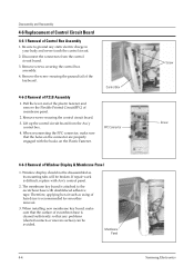
... replacement of the defective component parts of the door, reassemble it in the direction necessary for proper installation and adjustment so as the control circuit board, blower motor or high voltage transformer is not mounted properly, microwave energy may leak from base plate by nipper. 4. Take out the glass tray and the guide roller from the drive motor. 5. Disconnect the oven from the power source. 2. Screw the drive motor cover...
... replacement of the defective component parts of the door, reassemble it in the direction necessary for proper installation and adjustment so as the control circuit board, blower motor or high voltage transformer is not mounted properly, microwave energy may leak from base plate by nipper. 4. Take out the glass tray and the guide roller from the drive motor. 5. Disconnect the oven from the power source. 2. Screw the drive motor cover...
Service Manual
Page 10
... adhesive tape. Window display should not be broken. When installing new membrane key board, make sure that the holes on the connector are properly engaged with Ass'y control panel. 2. Membrane Panel 4-4 Screw Screw Samsung Electronics Disassembly and Reassembly 4-6 Replacement of Control Circuit Board 4-6-1 Removal of Window Display & Membrane Panel 1. Therefore, applying hot air such as its mounting tabs will be disassembled as using of escutcheon base is...
... adhesive tape. Window display should not be broken. When installing new membrane key board, make sure that the holes on the connector are properly engaged with Ass'y control panel. 2. Membrane Panel 4-4 Screw Screw Samsung Electronics Disassembly and Reassembly 4-6 Replacement of Control Circuit Board 4-6-1 Removal of Window Display & Membrane Panel 1. Therefore, applying hot air such as its mounting tabs will be disassembled as using of escutcheon base is...
Service Manual
Page 11
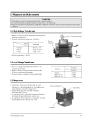
... Transformer 1. High voltage is located on the control circuit board. 2. The low voltage transformer is present at the high voltage terminals during any oven components or wiring, always unplug the oven from the circuit by disconnecting its power source and discharge the high voltage capacitor. 5-1 High Voltage Transformer 1. Magnetron Antenna Gasket Plate Cooling Fins Samsung Electronics 5-1 5. Remove the low voltage transformer from...
... Transformer 1. High voltage is located on the control circuit board. 2. The low voltage transformer is present at the high voltage terminals during any oven components or wiring, always unplug the oven from the circuit by disconnecting its power source and discharge the high voltage capacitor. 5-1 High Voltage Transformer 1. Magnetron Antenna Gasket Plate Cooling Fins Samsung Electronics 5-1 5. Remove the low voltage transformer from...
Service Manual
Page 12
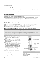
... of the diode (otherwise an infinite resistance may be sure to use the correct part number for the following switches: Primary interlock and door sensing switches, and the interlock monitor switch (replace all latch switches again by following the components test procedures. 5. When mounting Primary switch and Interlock Monitor switch to the oven assembly. 4. After repair and adjustment, be read the resistance. Make sure that the...
... of the diode (otherwise an infinite resistance may be sure to use the correct part number for the following switches: Primary interlock and door sensing switches, and the interlock monitor switch (replace all latch switches again by following the components test procedures. 5. When mounting Primary switch and Interlock Monitor switch to the oven assembly. 4. After repair and adjustment, be read the resistance. Make sure that the...
Service Manual
Page 13
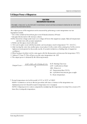
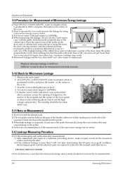
... NOT ALLOW EXPOSURE TO MICROWAVE RADIATION FROM MICROWAVE GENERATOR OR OTHER PARTS CONDUCTING MICROWAVE ENERGY. After moving the water into another glass vessel, place it in watts is marginal. The output power is 9.9ûC to high power and operate for 44 seconds exactly. (3 seconds included as a holding time of centigrade temperature. Equipment needed : * Two 1-liter cylindrical borosilicate glass vessel (Outside diameter 190 mm...
... NOT ALLOW EXPOSURE TO MICROWAVE RADIATION FROM MICROWAVE GENERATOR OR OTHER PARTS CONDUCTING MICROWAVE ENERGY. After moving the water into another glass vessel, place it in watts is marginal. The output power is 9.9ûC to high power and operate for 44 seconds exactly. (3 seconds included as a holding time of centigrade temperature. Equipment needed : * Two 1-liter cylindrical borosilicate glass vessel (Outside diameter 190 mm...
Service Manual
Page 14
... oven. 2) Start to operate the oven and measure the leakage by its manufacturer. 5-4 Samsung Electronics Remove the outer panel. 2. If the leakage testing of the cabinet door seam is graduated to 2,450MHz. 5. this manual notift that the probe end at the highest power level. 4. CENTRAL SERVICE CENTER 5-12-2 At least once a year have the microwave energy survey meter checked for Microwave Leakage 1. Set survey meter dual ranges...
... oven. 2) Start to operate the oven and measure the leakage by its manufacturer. 5-4 Samsung Electronics Remove the outer panel. 2. If the leakage testing of the cabinet door seam is graduated to 2,450MHz. 5. this manual notift that the probe end at the highest power level. 4. CENTRAL SERVICE CENTER 5-12-2 At least once a year have the microwave energy survey meter checked for Microwave Leakage 1. Set survey meter dual ranges...
Service Manual
Page 15
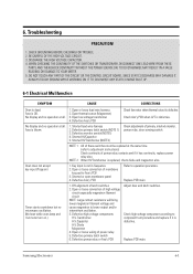
... lead wire harness 2. Open thermal cutout (Magnetron) 3. Defective monitor switch (NOTE1) 4. Shorted HVCapacitor 5. NOTE 2: When HVTransformer is blown. 1. No display and no microwave oscillation. (No heat while oven lamp and fan motor turn on.) 1. Timer starts countdown but no operation at all . Samsung Electronics 6-1 Shorted HVTransformer (NOTE2) Check adjustment of membrane key pad to component test procedure and replace if it has continuity, replace power relay also. Shorted or open membrane panel...
... lead wire harness 2. Open thermal cutout (Magnetron) 3. Defective monitor switch (NOTE1) 4. Shorted HVCapacitor 5. NOTE 2: When HVTransformer is blown. 1. No display and no microwave oscillation. (No heat while oven lamp and fan motor turn on.) 1. Timer starts countdown but no operation at all . Samsung Electronics 6-1 Shorted HVTransformer (NOTE2) Check adjustment of membrane key pad to component test procedure and replace if it has continuity, replace power relay also. Shorted or open membrane panel...
Service Manual
Page 16
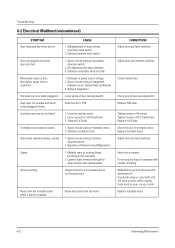
... of magnetron Loose wiring of microwave due to the plugged in power source voltage. 2. Uneven intensity of door sensing switch Defective Ass'y PCB 1. Inform the customer. Off-alignment of thermal cutout(Magnetron) 1. Noise from the motor. Operation of primary interlock 3. Tighten screws of fan motor. Loud buzzing noise can program but timer does not start. CORRECTIONS Adjust door and latch switches. Defective turntable motor. 1. Replace turntable motor. 6-2 Samsung Electronics Use plastic wrap or cover with gold or silver...
... of magnetron Loose wiring of microwave due to the plugged in power source voltage. 2. Uneven intensity of door sensing switch Defective Ass'y PCB 1. Inform the customer. Off-alignment of thermal cutout(Magnetron) 1. Noise from the motor. Operation of primary interlock 3. Tighten screws of fan motor. Loud buzzing noise can program but timer does not start. CORRECTIONS Adjust door and latch switches. Defective turntable motor. 1. Replace turntable motor. 6-2 Samsung Electronics Use plastic wrap or cover with gold or silver...
Service Manual
Page 18
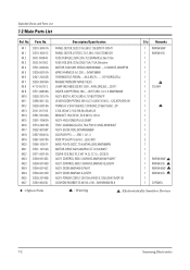
... TRAY-COOKING;GLASS,T6.0,PI318,1050G,MW5630T ASSY-GUIDE ROLLER;MW5896W COUPLER;PPS,-,-,-,3RD-1.0/1.3 FOOT;PP,H8,PI15.8x16.1,-,BLK,3RD BASE-PLATE;SGCC,T0.8,W345,L565,MW5896W MOTOR-DRIVE;M2HJ49ZR02,ST-16,50/60HZ COVER-CEILING;T0.3,W114.2,L121.5,-,CE2933 ASSY CONTROL-BOX;120V60HZ,MW5490W,P/WHT ASSY CONTROL-BOX;120V60HZ,MW5491G,D/GRY ASSY DOOR;MW5490,P/WHT ASSY DOOR;MW5491G,D/GRY ASSY POWER CORD...
... TRAY-COOKING;GLASS,T6.0,PI318,1050G,MW5630T ASSY-GUIDE ROLLER;MW5896W COUPLER;PPS,-,-,-,3RD-1.0/1.3 FOOT;PP,H8,PI15.8x16.1,-,BLK,3RD BASE-PLATE;SGCC,T0.8,W345,L565,MW5896W MOTOR-DRIVE;M2HJ49ZR02,ST-16,50/60HZ COVER-CEILING;T0.3,W114.2,L121.5,-,CE2933 ASSY CONTROL-BOX;120V60HZ,MW5490W,P/WHT ASSY CONTROL-BOX;120V60HZ,MW5491G,D/GRY ASSY DOOR;MW5490,P/WHT ASSY DOOR;MW5491G,D/GRY ASSY POWER CORD...
Service Manual
Page 19
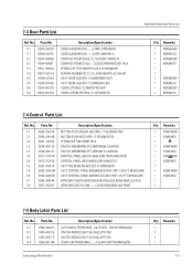
... ASSY CONTROL-PANEL;MW5491G,D/GRY,3RD-1.0CU.FT,NEWGUARD WINDOW-COVER HIDDEN;ABS(HR0370U),BLK,MW4390W,LCD-N/G WINDOW-DISPLAY;SAN,-,-,-,CLEAR,MW5490W,BLK PRINT Q'ty Remarks 1 MW5490W 1 MW5491G 1 1 MW5490W 1 MW5491G 1 MW5490W 1 MW5491G 1 1 MW5490W 1 MW5491G 1 1 7-5 Body Latch Parts List Ref. Parts No. Parts No. D 1 DE64-00037D D 1 DE64-00037E D 2 DE64-40006B D 2 DE64-40006F D 3 DE61-70032A D 4 DE67-00011A D 5 DE94-00073A D 5 DE94-00073B D 6 DE64-40012B D 6 DE64-40012A Description/Specification DOOR...
... ASSY CONTROL-PANEL;MW5491G,D/GRY,3RD-1.0CU.FT,NEWGUARD WINDOW-COVER HIDDEN;ABS(HR0370U),BLK,MW4390W,LCD-N/G WINDOW-DISPLAY;SAN,-,-,-,CLEAR,MW5490W,BLK PRINT Q'ty Remarks 1 MW5490W 1 MW5491G 1 1 MW5490W 1 MW5491G 1 MW5490W 1 MW5491G 1 1 MW5490W 1 MW5491G 1 1 7-5 Body Latch Parts List Ref. Parts No. Parts No. D 1 DE64-00037D D 1 DE64-00037E D 2 DE64-40006B D 2 DE64-40006F D 3 DE61-70032A D 4 DE67-00011A D 5 DE94-00073A D 5 DE94-00073B D 6 DE64-40012B D 6 DE64-40012A Description/Specification DOOR...
Service Manual
Page 20
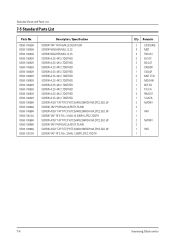
Exploded Views and Parts List 7-5 Standard Parts List Parts No. DE60-10059A DE60-10080A DE60-10080A DE60-10082H DE60-10082H DE60-10082H DE60-10082H DE60-10082H DE60-10082H DE60-10082H DE60-10082H DE60-10082H DE60-10082H DE60-10098A DE60-10088A DE60-10098A DE60-10012A DE60-10098A DE60-10088A DE60-10098A DE60-10012A Description / Specification SCREW-TAP TH;TH...
Exploded Views and Parts List 7-5 Standard Parts List Parts No. DE60-10059A DE60-10080A DE60-10080A DE60-10082H DE60-10082H DE60-10082H DE60-10082H DE60-10082H DE60-10082H DE60-10082H DE60-10082H DE60-10082H DE60-10082H DE60-10098A DE60-10088A DE60-10098A DE60-10012A DE60-10098A DE60-10088A DE60-10098A DE60-10012A Description / Specification SCREW-TAP TH;TH...

Service Manual
Page 23
... COM NO NC MONITOR SWITCH H. Schematic Diagrams 9-1 Schematic Diagrams FUSE 120V15A VARISTOR POWER CORD AC 120V/60Hz GND MGT CVT TCO CONDITION DOOR IS OPENED L.V.TRANS LAMP PRIMARY S/W BLK BLK BLK BLU YEL FAN MOTOR 125V 40W L 120V 21V FM 0V YEL YEL ORG RED DM D/MOTOR H. V. V. CAPACITOR MAIN RELAY PCB PATTERN BLU 0V F FA WHT RED MAGNETRON POWER RELAY (SECONDARY INTERLOCK) DOOR SENSING S/W ORG ORG ASSY...
... COM NO NC MONITOR SWITCH H. Schematic Diagrams 9-1 Schematic Diagrams FUSE 120V15A VARISTOR POWER CORD AC 120V/60Hz GND MGT CVT TCO CONDITION DOOR IS OPENED L.V.TRANS LAMP PRIMARY S/W BLK BLK BLK BLU YEL FAN MOTOR 125V 40W L 120V 21V FM 0V YEL YEL ORG RED DM D/MOTOR H. V. V. CAPACITOR MAIN RELAY PCB PATTERN BLU 0V F FA WHT RED MAGNETRON POWER RELAY (SECONDARY INTERLOCK) DOOR SENSING S/W ORG ORG ASSY...


