
Open Source Guide (ENGLISH)
Page 1
... as a special exception, the source code distributed need to control compilation and installation of the executable. Each version is safest to control the distribution of the GPL and LGPL. If you from the conditions of this License. For software which are designed to incorporate parts of the Program into another work based on the Program) on the Program, and copy and distribute such...
... as a special exception, the source code distributed need to control compilation and installation of the executable. Each version is safest to control the distribution of the GPL and LGPL. If you from the conditions of this License. For software which are designed to incorporate parts of the Program into another work based on the Program) on the Program, and copy and distribute such...
Open Source Guide (ENGLISH)
Page 2
... public, we recommend making it free software that everyone can do so by permitting redistribution under these terms (or, alternatively, under the terms of the greatest possible use to the library. IN NO ...LIBRARY TO OPERATE WITH ANY OTHER SOFTWARE), EVEN IF SUCH HOLDER OR OTHER PARTY HAS BEEN ADVISED OF THE POSSIBILITY OF SUCH DAMAGES. It is found. You can redistribute and change. How to...source file to where the full notice is safest to attach them to the start of each file should have at least the "copyright" line and a pointer to most effectively convey the exclusion of warranty...
... public, we recommend making it free software that everyone can do so by permitting redistribution under these terms (or, alternatively, under the terms of the greatest possible use to the library. IN NO ...LIBRARY TO OPERATE WITH ANY OTHER SOFTWARE), EVEN IF SUCH HOLDER OR OTHER PARTY HAS BEEN ADVISED OF THE POSSIBILITY OF SUCH DAMAGES. It is found. You can redistribute and change. How to...source file to where the full notice is safest to attach them to the start of each file should have at least the "copyright" line and a pointer to most effectively convey the exclusion of warranty...
User Manual (ENGLISH)
Page 4
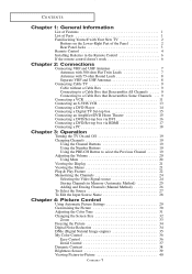
... Previous Channel . . . . . 19 Adjusting the Volume 20 Using Mute 20 Viewing the Display 21 Viewing the Menus 21 Plug & Play Feature 22 Memorizing the Channels 24 Selecting the Video Signal-source 24 Storing Channels in Memory (Automatic Method 25 Adding and Erasing Channels (Manual Method 26 To Select the Source 27 To Edit the Input Source Name 28 Chapter 4: Picture Control Using Automatic Picture Settings 29 Customizing the Picture 30 Adjusting the Color Tone 31 Changing the Screen Size 32...
... Previous Channel . . . . . 19 Adjusting the Volume 20 Using Mute 20 Viewing the Display 21 Viewing the Menus 21 Plug & Play Feature 22 Memorizing the Channels 24 Selecting the Video Signal-source 24 Storing Channels in Memory (Automatic Method 25 Adding and Erasing Channels (Manual Method 26 To Select the Source 27 To Edit the Input Source Name 28 Chapter 4: Picture Control Using Automatic Picture Settings 29 Customizing the Picture 30 Adjusting the Color Tone 31 Changing the Screen Size 32...
User Manual (ENGLISH)
Page 5
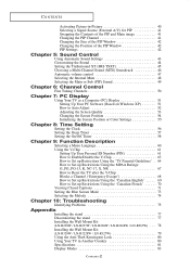
... volume control 47 Selecting the Internal Mute 48 Selecting the Main or Sub (PIP) Sound 49 Chapter 6: Channel Control Fine Tuning Channels 50 Chapter 7: PC Display Using Your TV as a Computer (PC) Display 51 Setting Up Your PC Software (Based on Windows XP 51 How to Auto Adjust 52 Adjusting the Screen Quality 53 Changing the Screen Position 54 Initializing the Screen Position or Color Settings 55 Chapter 8: Time Setting Setting the Clock 56 Setting the Sleep Timer...
... volume control 47 Selecting the Internal Mute 48 Selecting the Main or Sub (PIP) Sound 49 Chapter 6: Channel Control Fine Tuning Channels 50 Chapter 7: PC Display Using Your TV as a Computer (PC) Display 51 Setting Up Your PC Software (Based on Windows XP 51 How to Auto Adjust 52 Adjusting the Screen Quality 53 Changing the Screen Position 54 Initializing the Screen Position or Color Settings 55 Chapter 8: Time Setting Setting the Clock 56 Setting the Sleep Timer...
User Manual (ENGLISH)
Page 6
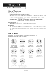
... system enables you to implement perfect digital sound and picture quality. - Remote Control (BN59-00455A) & Batteries (AAA x 2) RF Cable (AA39-00039A) Power Cord (3903-000085) Anynet Cable (BN39-00518B) Cleaning Cloth (BN63-01798A) Owner's Instructions Anynet AV Owner's Instructions M4 X L16 Stand Screw (6002-001294) x 4 Cover-Bottom (BN63-01674A) Stand (23", 26" BN96-01727A) (32" BN96-01733A) English-1 My Color Control: Colors can be set to create optimum contrast. - SRS...
... system enables you to implement perfect digital sound and picture quality. - Remote Control (BN59-00455A) & Batteries (AAA x 2) RF Cable (AA39-00039A) Power Cord (3903-000085) Anynet Cable (BN39-00518B) Cleaning Cloth (BN63-01798A) Owner's Instructions Anynet AV Owner's Instructions M4 X L16 Stand Screw (6002-001294) x 4 Cover-Bottom (BN63-01674A) Stand (23", 26" BN96-01727A) (32" BN96-01733A) English-1 My Color Control: Colors can be set to create optimum contrast. - SRS...
User Manual (ENGLISH)
Page 7
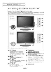
LN-R238W - LN-R3228W - SOURCE Displays a menu of all of the surrounding environment. Also used to select items on the on . This sensor works when the Brightness Sensor is on -screen menu. LN-R2668W - LN-R328W - LN-R267W - LN-R237W - POWER INDICATOR Blinks and turns off . Also used to confirm your choice on the on and lights up in stand-by detecting brightness of the available input sources (TV, AV1, AV2, S-Video, Component 1, Component 2, PC, HDMI). Also press...
LN-R238W - LN-R3228W - SOURCE Displays a menu of all of the surrounding environment. Also used to select items on the on . This sensor works when the Brightness Sensor is on -screen menu. LN-R2668W - LN-R328W - LN-R267W - LN-R237W - POWER INDICATOR Blinks and turns off . Also used to confirm your choice on the on and lights up in stand-by detecting brightness of the available input sources (TV, AV1, AV2, S-Video, Component 1, Component 2, PC, HDMI). Also press...
User Manual (ENGLISH)
Page 8
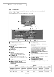
.... POWER INPUT Connect the supplied power cord. KENSINGTON LOCK Refer to a cable TV system. Anynet Refer to connect an A/V component that will be connected continuously such as a VCR or a DVD player. Use the HDMI/DVI terminal for external devices, such as a camcorder or VCR. You should use the DVI-to an external device. G E N E R A L I N F O R M AT I O N Rear Panel Jacks Use the rear panel jacks to "Anynet AV Owner's Instructions". For more information on your amplifier. COMPONENT IN 1, 2 Connect component video/audio from a DVD/Set...
.... POWER INPUT Connect the supplied power cord. KENSINGTON LOCK Refer to a cable TV system. Anynet Refer to connect an A/V component that will be connected continuously such as a VCR or a DVD player. Use the HDMI/DVI terminal for external devices, such as a camcorder or VCR. You should use the DVI-to an external device. G E N E R A L I N F O R M AT I O N Rear Panel Jacks Use the rear panel jacks to "Anynet AV Owner's Instructions". For more information on your amplifier. COMPONENT IN 1, 2 Connect component video/audio from a DVD/Set...
User Manual (ENGLISH)
Page 10
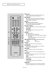
... Anynet button to bring up the Anynet menu. (Refer to "Anynet AV Owner's Instructions".) S.MODE Adjusts the TV sound by selecting one of the preset factory settings (or selects your remote does not work, change the screen size. (See page 33) PC Press to switch to the PC mode. (See pages 52~55) SWAP Press to interchange the main picture and the sub (PIP) picture. (See page 41) SIZE Press...
... Anynet button to bring up the Anynet menu. (Refer to "Anynet AV Owner's Instructions".) S.MODE Adjusts the TV sound by selecting one of the preset factory settings (or selects your remote does not work, change the screen size. (See page 33) PC Press to switch to the PC mode. (See pages 52~55) SWAP Press to interchange the main picture and the sub (PIP) picture. (See page 41) SIZE Press...

User Manual (ENGLISH)
Page 14
... "ANT IN", "VHF IN" or simply, "IN". CONNECTIONS Connecting Cable TV To connect to a cable TV system, follow the instructions below . Connecting to a Cable Box that Descrambles All Channels 1 Find the cable that Descrambles Some Channels If your cable box. Because this cable to the ANT IN terminal on back of the TV. Connecting to view unscrambled cable channels. Cable without a Cable Box 1 Plug the incoming cable into the ANT IN terminal on the...
... "ANT IN", "VHF IN" or simply, "IN". CONNECTIONS Connecting Cable TV To connect to a cable TV system, follow the instructions below . Connecting to a Cable Box that Descrambles All Channels 1 Find the cable that Descrambles Some Channels If your cable box. Because this cable to the ANT IN terminal on back of the TV. Connecting to view unscrambled cable channels. Cable without a Cable Box 1 Plug the incoming cable into the ANT IN terminal on the...
User Manual (ENGLISH)
Page 16
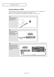
CONNECTIONS Connecting a VCR These instructions assume that you have already connected your TV to an antenna or a cable TV system (according to the instructions on pages 7-10). VCR Rear Panel TV Rear Panel RF Cable English-11 Incoming Cable or Antenna VCR Rear Panel 3 Connect an RF cable between the ANT OUT terminal on the VCR and the ANT IN terminal on the back of the TV. 2 Connect the cable or antenna to an antenna or a cable system. 1 Unplug the cable or antenna from the back of the VCR. Skip step 1 if you have not yet connected to the ANT IN terminal on the TV.
CONNECTIONS Connecting a VCR These instructions assume that you have already connected your TV to an antenna or a cable TV system (according to the instructions on pages 7-10). VCR Rear Panel TV Rear Panel RF Cable English-11 Incoming Cable or Antenna VCR Rear Panel 3 Connect an RF cable between the ANT OUT terminal on the VCR and the ANT IN terminal on the back of the TV. 2 Connect the cable or antenna to an antenna or a cable system. 1 Unplug the cable or antenna from the back of the VCR. Skip step 1 if you have not yet connected to the ANT IN terminal on the TV.

User Manual (ENGLISH)
Page 21
DVD Player Rear Panel TV Rear Panel DVI-to-HDMI Cable (Option) 2 Connect an audio cable between the HDMI/DVI connector on the TV and the DVI connector on the DVD player/Set-top box. DVD Player Rear Panel TV Rear Panel Audio Cable (Option) DVI-to-HDMI Cable (Option) English-16 CONNECTIONS Connecting a DVD/Set-top box via DVI This can be applied only if there is the DVI Output connector on the external device. 1 Connect a DVI-to-HDMI cable or DVI-HDMI adapter between the DVI IN [R-AUDIO-L] jack on the TV and the AUDIO OUT jacks on the DVD player/Set-top box.
DVD Player Rear Panel TV Rear Panel DVI-to-HDMI Cable (Option) 2 Connect an audio cable between the HDMI/DVI connector on the TV and the DVI connector on the DVD player/Set-top box. DVD Player Rear Panel TV Rear Panel Audio Cable (Option) DVI-to-HDMI Cable (Option) English-16 CONNECTIONS Connecting a DVD/Set-top box via DVI This can be applied only if there is the DVI Output connector on the external device. 1 Connect a DVI-to-HDMI cable or DVI-HDMI adapter between the DVI IN [R-AUDIO-L] jack on the TV and the AUDIO OUT jacks on the DVD player/Set-top box.
User Manual (ENGLISH)
Page 22
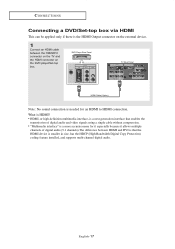
..., is a next-generation interface that enables the transmission of digital audio and video signals using a single cable without compression. • "Multimedia interface" is needed for it especially because it allows multiple channels of digital audio (5.1 channels).The difference between the HDMI/DVI connector on the TV and the HDMI connector on the DVD player/Set-top box. DVD Player Rear Panel TV Rear Panel HDMI Cable (Option) Note: No sound connection is a more accurate name for an...
..., is a next-generation interface that enables the transmission of digital audio and video signals using a single cable without compression. • "Multimedia interface" is needed for it especially because it allows multiple channels of digital audio (5.1 channels).The difference between the HDMI/DVI connector on the TV and the HDMI connector on the DVD player/Set-top box. DVD Player Rear Panel TV Rear Panel HDMI Cable (Option) Note: No sound connection is a more accurate name for an...

User Manual (ENGLISH)
Page 24
..., tune to select the Previous Channel 1 Press the PRE-CH button. English-19 buttons to When you use the PRE-CH button to the last channel viewed. See pages 22-23 to a channel. Chapter 3 O P E R AT I O N Turning the TV On and Off 1 Press the POWER button on the front of the panel. You will switch to quickly alternate between two channels that the TV has memorized...
..., tune to select the Previous Channel 1 Press the PRE-CH button. English-19 buttons to When you use the PRE-CH button to the last channel viewed. See pages 22-23 to a channel. Chapter 3 O P E R AT I O N Turning the TV On and Off 1 Press the POWER button on the front of the panel. You will switch to quickly alternate between two channels that the TV has memorized...
User Manual (ENGLISH)
Page 26
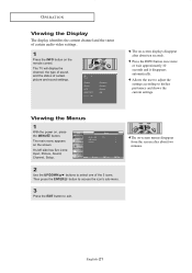
... access the icon's sub-menu. 3 Press the EXIT button to his/her preference and shows the current settings. It's left side has five icons: Input, Picture, Sound, Channel, Setup. 2 Use the UP/DOWN buttons to select one of certain picture and sound settings. The on , press the MENU button. The TV will display the channel, the type of sound, and the status of the 5 icons. Viewing the Menus 1 With the power on -screen displays...
... access the icon's sub-menu. 3 Press the EXIT button to his/her preference and shows the current settings. It's left side has five icons: Input, Picture, Sound, Channel, Setup. 2 Use the UP/DOWN buttons to select one of certain picture and sound settings. The on , press the MENU button. The TV will display the channel, the type of sound, and the status of the 5 icons. Viewing the Menus 1 With the power on -screen displays...
User Manual (ENGLISH)
Page 40
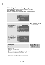
... DNIe pictures. • By default, the product displays the picture with contrast, white enhancement and 3D noise reduction. The left-hand side of the screen shows the improved DNIe image. Alternate method: Press the DNIe button under the remote's cover to display the menu. You can see how DNIe improves the picture by setting DNIe demo mode to On. 1 Press the MENU button to change the DNIe Demo mode...
... DNIe pictures. • By default, the product displays the picture with contrast, white enhancement and 3D noise reduction. The left-hand side of the screen shows the improved DNIe image. Alternate method: Press the DNIe button under the remote's cover to display the menu. You can see how DNIe improves the picture by setting DNIe demo mode to On. 1 Press the MENU button to change the DNIe Demo mode...
User Manual (ENGLISH)
Page 69
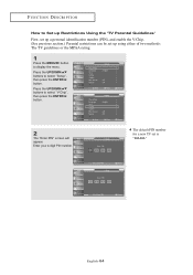
... your 4-digit PIN number. The default PIN number for a new TV set up using either of two methods: The TV guidelines or the MPAA rating. 1 Press the MENU button to display the menu. Press the UP/DOWN buttons to select "V-Chip", then press the ENTER button. 2 The "Enter PIN" screen will appear. FUNCTION DESCRIPTION How to Set up Restrictions Using the 'TV Parental Guidelines' First, set up...
... your 4-digit PIN number. The default PIN number for a new TV set up using either of two methods: The TV guidelines or the MPAA rating. 1 Press the MENU button to display the menu. Press the UP/DOWN buttons to select "V-Chip", then press the ENTER button. 2 The "Enter PIN" screen will appear. FUNCTION DESCRIPTION How to Set up Restrictions Using the 'TV Parental Guidelines' First, set up...

User Manual (ENGLISH)
Page 80
... sound or sound is too light or too dark. Remote control malfunctions "Check signal cable" message. Possible Solution Try another channel. Adjust the antenna. Ensure that the signal cable is plugged in the Display Modes. Adjust the Coarse tuning and then adjust the Fine tuning. The image is too low at maximum volume. Try another channel. Check the antenna connections. Unplug the TV for 30 seconds, then try this list of possible problems...
... sound or sound is too light or too dark. Remote control malfunctions "Check signal cable" message. Possible Solution Try another channel. Adjust the antenna. Ensure that the signal cable is plugged in the Display Modes. Adjust the Coarse tuning and then adjust the Fine tuning. The image is too low at maximum volume. Try another channel. Check the antenna connections. Unplug the TV for 30 seconds, then try this list of possible problems...
User Manual (ENGLISH)
Page 81
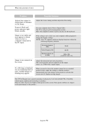
When you have no impact on the keyboard. Screen is not correct, use your computer check: Power, Signal Cable. If the setting is black and power indicator light blinks steadily. English-76 On your computer utility program to change the display settings. These pixels will have a computer connected to the PC input. STB) with a digital signal. Image is using its power management system. The TV is not stable and may be...
When you have no impact on the keyboard. Screen is not correct, use your computer check: Power, Signal Cable. If the setting is black and power indicator light blinks steadily. English-76 On your computer utility program to change the display settings. These pixels will have a computer connected to the PC input. STB) with a digital signal. Image is using its power management system. The TV is not stable and may be...
User Manual (ENGLISH)
Page 83
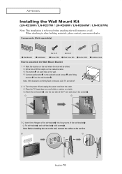
... on the wall, connect the cables to the set -bracket and wall-bracket with wood screws after fitting anchors into the grooves of 35mm depth on the marked location. Fix set first. Drill a hole of the wall-bracket . English-78 APPENDIX Installing the Wall Mount Kit (LN-R238W / LN-R237W / LN-R268W / LN-R2668W / LN-R267W) Note: This installation is not firmly fixed to the wall, LCD TV can fall off and unplug the power cord from...
... on the wall, connect the cables to the set -bracket and wall-bracket with wood screws after fitting anchors into the grooves of 35mm depth on the marked location. Fix set first. Drill a hole of the wall-bracket . English-78 APPENDIX Installing the Wall Mount Kit (LN-R238W / LN-R237W / LN-R268W / LN-R2668W / LN-R267W) Note: This installation is not firmly fixed to the wall, LCD TV can fall off and unplug the power cord from...
User Manual (ENGLISH)
Page 84
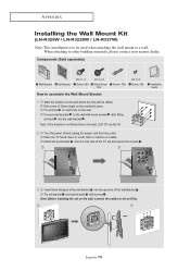
... of 35mm depth on the wall where the hole will be used when attaching the wall mount to a wall. Installation Guide 2 Turn the power off . English-79 APPENDIX Installing the Wall Mount Kit (LN-R328W / LN-R3228W / LN-R327W) Note: This installation is not firmly fixed to the wall, LCD TV can fall off and unplug the power cord from the outlet. Drill a hole of the wall-bracket . Fix set first. Place the TV faced...
... of 35mm depth on the wall where the hole will be used when attaching the wall mount to a wall. Installation Guide 2 Turn the power off . English-79 APPENDIX Installing the Wall Mount Kit (LN-R328W / LN-R3228W / LN-R327W) Note: This installation is not firmly fixed to the wall, LCD TV can fall off and unplug the power cord from the outlet. Drill a hole of the wall-bracket . Fix set first. Place the TV faced...


