

User Manual (ENGLISH)
Page 2
... for extended periods of light transmission will also remain varied and as you may experience temporary or permanent image burn. • Digital Ready TV: When the TV receives HD-grade signals (and the set -top box output is 1080i). When you watch a digital HD-grade broadcast on a regular... of time, the amount of the screen are cropped. Precautions When Displaying a Still Image A still image may cause permanent damage to the TV screen. • Digital Ready TV: When you select the regular screen (4:3) mode to watch an SD-grade digital broadcast (and the set-top box output is 480p). &#...
... for extended periods of light transmission will also remain varied and as you may experience temporary or permanent image burn. • Digital Ready TV: When the TV receives HD-grade signals (and the set -top box output is 1080i). When you watch a digital HD-grade broadcast on a regular... of time, the amount of the screen are cropped. Precautions When Displaying a Still Image A still image may cause permanent damage to the TV screen. • Digital Ready TV: When you select the regular screen (4:3) mode to watch an SD-grade digital broadcast (and the set-top box output is 480p). &#...

User Manual (ENGLISH)
Page 3
...into digital form, in pause mode for extended periods of time as you connect a DVD player, computer or a game console to the TV and select the 4:3 screen mode. If you may experience temporary or permanent image burn. Note: If the borders at the left and ... mode for extended periods of the screen are cropped. • Integrated Digital TV (Wide-screen): When the TV receives SD-grade (regular) broadcasting signals (receives 480p regular signals). • Digital Ready TV (wide-screen): digital TV: When the TV receives SD-grade (regular) broadcasting signals (with a set-top box). &#...
...into digital form, in pause mode for extended periods of time as you connect a DVD player, computer or a game console to the TV and select the 4:3 screen mode. If you may experience temporary or permanent image burn. Note: If the borders at the left and ... mode for extended periods of the screen are cropped. • Integrated Digital TV (Wide-screen): When the TV receives SD-grade (regular) broadcasting signals (receives 480p regular signals). • Digital Ready TV (wide-screen): digital TV: When the TV receives SD-grade (regular) broadcasting signals (with a set-top box). &#...
User Manual (ENGLISH)
Page 4
... Connecting VHF and UHF Antennas 7 Antennas with 300-ohm Flat Twin Leads 7 Antennas with 75-ohm Round Leads 8 Separate VHF and UHF Antennas 8 Connecting Cable TV 9 Cable without a Cable Box 9 Connecting to a Cable Box that Descrambles All Channels . . . . . 9 Connecting to a Cable Box that Descrambles Some... Channels . . . 9 Connecting a VCR 11 Connecting an S-VHS VCR 13 Connecting a DVD Player 14 Connecting a Digital TV Set-top box 15 Connecting an Amplifier/DVD Home Theater 15 Connecting a DVD/Set-top box via DVI 16 Connecting a DVD/Set-top box via...
... Connecting VHF and UHF Antennas 7 Antennas with 300-ohm Flat Twin Leads 7 Antennas with 75-ohm Round Leads 8 Separate VHF and UHF Antennas 8 Connecting Cable TV 9 Cable without a Cable Box 9 Connecting to a Cable Box that Descrambles All Channels . . . . . 9 Connecting to a Cable Box that Descrambles Some... Channels . . . 9 Connecting a VCR 11 Connecting an S-VHS VCR 13 Connecting a DVD Player 14 Connecting a Digital TV Set-top box 15 Connecting an Amplifier/DVD Home Theater 15 Connecting a DVD/Set-top box via DVI 16 Connecting a DVD/Set-top box via...
User Manual (ENGLISH)
Page 5
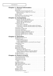
... Mute 48 Selecting the Main or Sub (PIP) Sound 49 Chapter 6: Channel Control Fine Tuning Channels 50 Chapter 7: PC Display Using Your TV as a Computer (PC) Display 51 Setting Up Your PC Software (Based on Windows XP 51 How to Auto Adjust 52 Adjusting the Screen... the stand 77 Disconnecting the stand 77 Installing the Wall Mount Kit (LN-R238W / LN-R237W / LN-R268W / LN-R2668W / LN-R267W) . . . 78 Installing the Wall Mount Kit (LN-R328W / LN-R3228W / LN-R327W 79 Using the Anti-Theft Kensington Lock 80 Using Your TV in Another Country 80 Specifications 81 Display Modes 83 Contents-2
... Mute 48 Selecting the Main or Sub (PIP) Sound 49 Chapter 6: Channel Control Fine Tuning Channels 50 Chapter 7: PC Display Using Your TV as a Computer (PC) Display 51 Setting Up Your PC Software (Based on Windows XP 51 How to Auto Adjust 52 Adjusting the Screen... the stand 77 Disconnecting the stand 77 Installing the Wall Mount Kit (LN-R238W / LN-R237W / LN-R268W / LN-R2668W / LN-R267W) . . . 78 Installing the Wall Mount Kit (LN-R328W / LN-R3228W / LN-R327W 79 Using the Anti-Theft Kensington Lock 80 Using Your TV in Another Country 80 Specifications 81 Display Modes 83 Contents-2
User Manual (ENGLISH)
Page 6
... the screen brightness automatically depending on the brightness of the surrounding environment. The TV utilizes the HDMI system to create optimum contrast. - If any items are included with your LCD TV. Dynamic Contrast: Automatically detects the input visual signal and adjusts to implement perfect... digital sound and picture quality. - My Color Control: Colors can be set to easily control Samsung audio-video (AV) devices from this TV. The Anynet system enables ...
... the screen brightness automatically depending on the brightness of the surrounding environment. The TV utilizes the HDMI system to create optimum contrast. - If any items are included with your LCD TV. Dynamic Contrast: Automatically detects the input visual signal and adjusts to implement perfect... digital sound and picture quality. - My Color Control: Colors can be set to easily control Samsung audio-video (AV) devices from this TV. The Anynet system enables ...
User Manual (ENGLISH)
Page 7
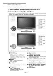
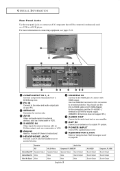
.... POWER INDICATOR Blinks and turns off . REMOTE CONTROL SENSOR Aim the remote control towards this spot on -screen menu of your TV's features. - MENU Press to select items on the on the model. LN-R327W Note: The product color may vary depending on -screen menu. Also used to turn the... on the Lower-Right Part of the Panel The buttons on the lower-right panel control your TV's basic features, including the on and off when the power is on. LN-R2668W - LN-R267W - Also press to highlight various items on the on-screen menu. (POWER) Press to confirm your choice on ...
.... POWER INDICATOR Blinks and turns off . REMOTE CONTROL SENSOR Aim the remote control towards this spot on -screen menu of your TV's features. - MENU Press to select items on the on the model. LN-R327W Note: The product color may vary depending on -screen menu. Also used to turn the... on the Lower-Right Part of the Panel The buttons on the lower-right panel control your TV's basic features, including the on and off when the power is on. LN-R2668W - LN-R267W - Also press to highlight various items on the on-screen menu. (POWER) Press to confirm your choice on ...
User Manual (ENGLISH)
Page 8
... use the DVI-to-HDMI cable or DVI-HDMI Adapter for the connection, and the 'R -AUDIO -L' terminal on DVI-IN for DVI connection to a cable TV system. Speaker RF Internal Mute Off Speaker Output Internal Mute On Mute Video No Signal Mute AV, S-Video Speaker Output Mute Mute Audio Out Component...
... use the DVI-to-HDMI cable or DVI-HDMI Adapter for the connection, and the 'R -AUDIO -L' terminal on DVI-IN for DVI connection to a cable TV system. Speaker RF Internal Mute Off Speaker Output Internal Mute On Mute Video No Signal Mute AV, S-Video Speaker Output Mute Mute Audio Out Component...
User Manual (ENGLISH)
Page 9
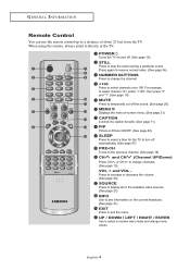
When using the remote, always point it directly at the TV. For example, to select channel 121, press "+100", then press "2" and "1". (See page 19) MUTE ...decoder. (See page 71) PIP Picture-in-Picture ON/OFF. (See page 40) SLEEP Press to select a time for the TV to turn off . (See page 19) STILL Press to select channels over 100. Press again to resume normal video. (See... (See page 27) INFO Use to see information on -screen menu items and change menu values. English-4 POWER Turns the TV on and off automatically. (See page 57) PRE-CH Tunes to the previous channel. (See page 19) CH and CH...
When using the remote, always point it directly at the TV. For example, to select channel 121, press "+100", then press "2" and "1". (See page 19) MUTE ...decoder. (See page 71) PIP Picture-in-Picture ON/OFF. (See page 40) SLEEP Press to select a time for the TV to turn off . (See page 19) STILL Press to select channels over 100. Press again to resume normal video. (See... (See page 27) INFO Use to see information on -screen menu items and change menu values. English-4 POWER Turns the TV on and off automatically. (See page 57) PRE-CH Tunes to the previous channel. (See page 19) CH and CH...
User Manual (ENGLISH)
Page 10
... Audio Program (SAP broadcast). (See page 46) AUTO PROG. Fast Forward SRS Selects TruSurround XT mode. (See page 45) P.MODE Adjusts the TV picture by selecting one of the preset factory settings. (See page 29) P.SIZE Press to change the batteries and press the RESET button for 2-3.... G E N E R A L I N F O R M AT I O N Anynet Press the Anynet button to bring up the Anynet menu. (Refer to "Anynet AV Owner's Instructions".) S.MODE Adjusts the TV sound by selecting one of the preset factory settings (or selects your remote does not work, change the screen size. (See page 33) PC Press...
... Audio Program (SAP broadcast). (See page 46) AUTO PROG. Fast Forward SRS Selects TruSurround XT mode. (See page 45) P.MODE Adjusts the TV picture by selecting one of the preset factory settings. (See page 29) P.SIZE Press to change the batteries and press the RESET button for 2-3.... G E N E R A L I N F O R M AT I O N Anynet Press the Anynet button to bring up the Anynet menu. (Refer to "Anynet AV Owner's Instructions".) S.MODE Adjusts the TV sound by selecting one of the preset factory settings (or selects your remote does not work, change the screen size. (See page 33) PC Press...
User Manual (ENGLISH)
Page 11
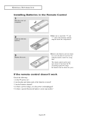
... following: 1. Is there a power outage, or is the power cord unplugged? 5. Make sure to about 23 feet from the TV. (Assuming typical TV usage, the batteries last for a long time. Is the TV power on? 2. English-6 Are the plus and minus ends of the batteries with the diagram inside the compartment. 3 Replace the...
... following: 1. Is there a power outage, or is the power cord unplugged? 5. Make sure to about 23 feet from the TV. (Assuming typical TV usage, the batteries last for a long time. Is the TV power on? 2. English-6 Are the plus and minus ends of the batteries with the diagram inside the compartment. 3 Replace the...

User Manual (ENGLISH)
Page 12
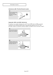
... and UHF Antennas If your antenna has one lead that looks like this , see "Antennas with 75-ohm Round Leads" on the back of the TV.
... and UHF Antennas If your antenna has one lead that looks like this , see "Antennas with 75-ohm Round Leads" on the back of the TV.
User Manual (ENGLISH)
Page 13
UHF VHF ANT IN English-8 Separate VHF and UHF Antennas If you have two separate antennas for your TV (one VHF and one UHF), you must combine the two antenna signals before connecting the antennas to the combiner. UHF VHF 2 Plug the combiner into the ANT IN terminal on the back of the TV. CONNECTIONS Antennas with 75-ohm Round Leads 1 Plug the antenna lead into the ANT IN terminal on the back of the TV. This procedure requires an optional combiner-adapter (available at most electronics shops). 1 Connect both antenna leads to the TV.
UHF VHF ANT IN English-8 Separate VHF and UHF Antennas If you have two separate antennas for your TV (one VHF and one UHF), you must combine the two antenna signals before connecting the antennas to the combiner. UHF VHF 2 Plug the combiner into the ANT IN terminal on the back of the TV. CONNECTIONS Antennas with 75-ohm Round Leads 1 Plug the antenna lead into the ANT IN terminal on the back of the TV. This procedure requires an optional combiner-adapter (available at most electronics shops). 1 Connect both antenna leads to the TV.

User Manual (ENGLISH)
Page 14
... might be labeled "ANT IN", "VHF IN" or simply, "IN". Because this cable to the ANT IN terminal on the back of this TV is connected to the ANT OUT terminal on your cable box descrambles only some channels (such as premium channels), follow the instructions below . Cable without.... Connecting to a Cable Box that is cable-ready, you do not need a two-way splitter, an RF (A/B) switch, and four lengths of the TV. English-9 Connecting to a Cable Box that Descrambles All Channels 1 Find the cable that Descrambles Some Channels If your cable box. CONNECTIONS Connecting Cable...
... might be labeled "ANT IN", "VHF IN" or simply, "IN". Because this cable to the ANT IN terminal on the back of this TV is connected to the ANT OUT terminal on your cable box descrambles only some channels (such as premium channels), follow the instructions below . Cable without.... Connecting to a Cable Box that is cable-ready, you do not need a two-way splitter, an RF (A/B) switch, and four lengths of the TV. English-9 Connecting to a Cable Box that Descrambles All Channels 1 Find the cable that Descrambles Some Channels If your cable box. CONNECTIONS Connecting Cable...

User Manual (ENGLISH)
Page 15
... RF (A/B) Switch 6 Connect the last RF cable between the other OUT terminal on the splitter and the A-IN terminal on the rear of the TV. Incoming cable Splitter 3 Connect an RF cable between the ANT OUT terminal on the cable box and the B-IN terminal on the cable box. ... RF cable between an OUTPUT terminal on the splitter and the IN terminal on the A/B switch. Incoming cable Splitter Cable Box RF (A/B) Switch ANT IN TV Rear After you've made this cable to a two-way splitter. CONNECTIONS 2 Connect this connection, set the A/B switch to "B", you will need to ...
... RF (A/B) Switch 6 Connect the last RF cable between the other OUT terminal on the splitter and the A-IN terminal on the rear of the TV. Incoming cable Splitter 3 Connect an RF cable between the ANT OUT terminal on the cable box and the B-IN terminal on the cable box. ... RF cable between an OUTPUT terminal on the splitter and the IN terminal on the A/B switch. Incoming cable Splitter Cable Box RF (A/B) Switch ANT IN TV Rear After you've made this cable to a two-way splitter. CONNECTIONS 2 Connect this connection, set the A/B switch to "B", you will need to ...
User Manual (ENGLISH)
Page 16
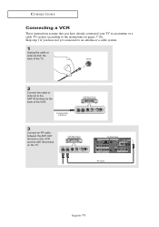
Skip step 1 if you have not yet connected to an antenna or a cable system. 1 Unplug the cable or antenna from the back of the TV. 2 Connect the cable or antenna to the instructions on pages 7-10). VCR Rear Panel TV Rear Panel RF Cable English-11 CONNECTIONS Connecting a VCR These instructions assume that you have already connected your TV to an antenna or a cable TV system (according to the ANT IN terminal on the back of the VCR. Incoming Cable or Antenna VCR Rear Panel 3 Connect an RF cable between the ANT OUT terminal on the VCR and the ANT IN terminal on the TV.
Skip step 1 if you have not yet connected to an antenna or a cable system. 1 Unplug the cable or antenna from the back of the TV. 2 Connect the cable or antenna to the instructions on pages 7-10). VCR Rear Panel TV Rear Panel RF Cable English-11 CONNECTIONS Connecting a VCR These instructions assume that you have already connected your TV to an antenna or a cable TV system (according to the ANT IN terminal on the back of the VCR. Incoming Cable or Antenna VCR Rear Panel 3 Connect an RF cable between the ANT OUT terminal on the VCR and the ANT IN terminal on the TV.

User Manual (ENGLISH)
Page 17
... "Viewing a VCR or Camcorder Tape" to the left and right audio input jacks of the TV. 5 Connect a video cable between the AUDIO OUT jacks on the VCR and the AV IN [R-AUDIO-L] jacks on the TV. CONNECTIONS 4 Connect an audio cable between the VIDEO OUT jack on the VCR and the AV... IN [VIDEO] jack on the TV. English-12 VCR Rear Panel TV Rear Panel Audio Cable (Option) RF Cable If you have a "mono" (non-stereo) VCR, use the Y-connector (not supplied) to hook up to view your...
... "Viewing a VCR or Camcorder Tape" to the left and right audio input jacks of the TV. 5 Connect a video cable between the AUDIO OUT jacks on the VCR and the AV IN [R-AUDIO-L] jacks on the TV. CONNECTIONS 4 Connect an audio cable between the VIDEO OUT jack on the VCR and the AV... IN [VIDEO] jack on the TV. English-12 VCR Rear Panel TV Rear Panel Audio Cable (Option) RF Cable If you have a "mono" (non-stereo) VCR, use the Y-connector (not supplied) to hook up to view your...

User Manual (ENGLISH)
Page 18
... Cable (Option) S-Video Cable (Option) RF Cable An S-Video cable is usually included with an S-VHS VCR. (If not, check your TV. CONNECTIONS Connecting an S-VHS VCR Your Samsung TV can be connected to an S-Video signal from an S-VHS VCR. (This connection delivers a better picture as compared to a standard VHS VCR... Panel RF Cable 2 Connect an audio cable between the S-VIDEO OUT jack on the VCR and the S-VIDEO IN jack on the TV. English-13 VCR Rear Panel TV Rear Panel Audio Cable (Option) RF Cable 3 Connect an S-Video cable between the AUDIO OUT jacks on the VCR and the AV...
... Cable (Option) S-Video Cable (Option) RF Cable An S-Video cable is usually included with an S-VHS VCR. (If not, check your TV. CONNECTIONS Connecting an S-VHS VCR Your Samsung TV can be connected to an S-Video signal from an S-VHS VCR. (This connection delivers a better picture as compared to a standard VHS VCR... Panel RF Cable 2 Connect an audio cable between the S-VIDEO OUT jack on the VCR and the S-VIDEO IN jack on the TV. English-13 VCR Rear Panel TV Rear Panel Audio Cable (Option) RF Cable 3 Connect an S-Video cable between the AUDIO OUT jacks on the VCR and the AV...

User Manual (ENGLISH)
Page 19
...Panel Note: For an explanation of Component video, see your DVD player owner's manual. CONNECTIONS Connecting a DVD Player The rear panel jacks on your TV make it easy to connect a DVD player to match the component video and audio connections. For example, if connecting the video cable to Component In... 1, connect the audio cable to Component In 1 also. * Each external input source device has a different back panel configuration. DVD Player Rear Panel TV Rear Panel Audio Cable (Option) 2 Connect a component cable between the COMPONENT IN 1 or COMPONENT IN 2 [R-AUDIO-L] jacks on the...
...Panel Note: For an explanation of Component video, see your DVD player owner's manual. CONNECTIONS Connecting a DVD Player The rear panel jacks on your TV make it easy to connect a DVD player to match the component video and audio connections. For example, if connecting the video cable to Component In... 1, connect the audio cable to Component In 1 also. * Each external input source device has a different back panel configuration. DVD Player Rear Panel TV Rear Panel Audio Cable (Option) 2 Connect a component cable between the COMPONENT IN 1 or COMPONENT IN 2 [R-AUDIO-L] jacks on the...
User Manual (ENGLISH)
Page 20
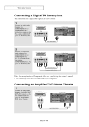
...Connect an audio cable between the AUDIO OUT [R-AUDIO-L] jacks on the TV and the AUDIO IN jacks on the Set-top box. Amplifier/DVD Home Theater TV Rear Panel Audio Cable (Option) English-15 CONNECTIONS Connecting a Digital TV Set-top box The connections for a typical Set-top box are ...below. 1 Connect an audio cable between the COMPONENT IN 1 or COMPONENT IN 2 [R-AUDIO-L] jacks on the TV and the AUDIO OUT jacks on the Amplifier/ DVD Home Theater. Set-Top Box Rear Panel TV Rear Panel Audio Cable (Option) 2 Connect a component cable between the COMPONENT IN 1 or COMPONENT IN 2 [...
...Connect an audio cable between the AUDIO OUT [R-AUDIO-L] jacks on the TV and the AUDIO IN jacks on the Set-top box. Amplifier/DVD Home Theater TV Rear Panel Audio Cable (Option) English-15 CONNECTIONS Connecting a Digital TV Set-top box The connections for a typical Set-top box are ...below. 1 Connect an audio cable between the COMPONENT IN 1 or COMPONENT IN 2 [R-AUDIO-L] jacks on the TV and the AUDIO OUT jacks on the Amplifier/ DVD Home Theater. Set-Top Box Rear Panel TV Rear Panel Audio Cable (Option) 2 Connect a component cable between the COMPONENT IN 1 or COMPONENT IN 2 [...

User Manual (ENGLISH)
Page 21
CONNECTIONS Connecting a DVD/Set-top box via DVI This can be applied only if there is the DVI Output connector on the external device. 1 Connect a DVI-to-HDMI cable or DVI-HDMI adapter between the DVI IN [R-AUDIO-L] jack on the TV and the AUDIO OUT jacks on the DVD player/Set-top box. DVD Player Rear Panel TV Rear Panel Audio Cable (Option) DVI-to -HDMI Cable (Option) 2 Connect an audio cable between the HDMI/DVI connector on the TV and the DVI connector on the DVD player/Set-top box. DVD Player Rear Panel TV Rear Panel DVI-to -HDMI Cable (Option) English-16
CONNECTIONS Connecting a DVD/Set-top box via DVI This can be applied only if there is the DVI Output connector on the external device. 1 Connect a DVI-to-HDMI cable or DVI-HDMI adapter between the DVI IN [R-AUDIO-L] jack on the TV and the AUDIO OUT jacks on the DVD player/Set-top box. DVD Player Rear Panel TV Rear Panel Audio Cable (Option) DVI-to -HDMI Cable (Option) 2 Connect an audio cable between the HDMI/DVI connector on the TV and the DVI connector on the DVD player/Set-top box. DVD Player Rear Panel TV Rear Panel DVI-to -HDMI Cable (Option) English-16


