Service Manual
Page 3
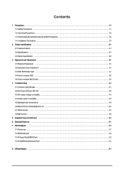
... to execute DDC ...3-2 3-5 How to execute MCU Code ...3-3 4. Electrical Parts List ...6-1 7. Block Diagram ...7-1 7-1 Power tree ...7-1 7-2 Mainboard part ...7-2 7-3 IP Board Part(SMPS Part) ...7-2 7-4 IP BOARD part(Inverter Part) ...7-3 8. Troubleshooting ...4-1 4-1 Common Acknowledge ...4-1 4-2 No Power & Power LED Off ...4-2 4-3 DC output voltage is unstable ...4-3 4-4 Output power is unstable ...4-4 4-5 Backlight can't be turned on ...4-5 4-6 Black Screen...
... to execute DDC ...3-2 3-5 How to execute MCU Code ...3-3 4. Electrical Parts List ...6-1 7. Block Diagram ...7-1 7-1 Power tree ...7-1 7-2 Mainboard part ...7-2 7-3 IP Board Part(SMPS Part) ...7-2 7-4 IP BOARD part(Inverter Part) ...7-3 8. Troubleshooting ...4-1 4-1 Common Acknowledge ...4-1 4-2 No Power & Power LED Off ...4-2 4-3 DC output voltage is unstable ...4-3 4-4 Output power is unstable ...4-4 4-5 Backlight can't be turned on ...4-5 4-6 Black Screen...
Service Manual
Page 4
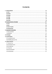
Circuit Descriptions ...13-1 13-1 Overall Block Structure ...13-1 13-2 IP BOARD part(Inverter Part) ...13-4 14. Contents 9. Schematic Diagrams ...9-1 9-1 INPUT ...9-1 9-2 DCINPUT ...9-2 9-3 SCALER ...9-3 9-4 POWER ...9-4 9-5 POWER ...9-5 9-6 KEYPAD ...9-6 10. PCB Diagram ...12-1 13. Reference Infomation ...14-1 14-1 Technical Terms ...14-1 14-2 Connecting the monitor ...14-3 14-3 Pin Assignments ...14-4 14-4 Timing Chart ...14-5 14-5 Preset Timing...
Circuit Descriptions ...13-1 13-1 Overall Block Structure ...13-1 13-2 IP BOARD part(Inverter Part) ...13-4 14. Contents 9. Schematic Diagrams ...9-1 9-1 INPUT ...9-1 9-2 DCINPUT ...9-2 9-3 SCALER ...9-3 9-4 POWER ...9-4 9-5 POWER ...9-5 9-6 KEYPAD ...9-6 10. PCB Diagram ...12-1 13. Reference Infomation ...14-1 14-1 Technical Terms ...14-1 14-2 Connecting the monitor ...14-3 14-3 Pin Assignments ...14-4 14-4 Timing Chart ...14-5 14-5 Preset Timing...
Service Manual
Page 18
If you check the H/V position, please use the crosshatch pattern. - If brightness uneven, repairs Inverter circuit or change panel. 4-1 If not, please re-write EDID or upload firmware into Flash memory via VGA Cable. - So if the entire screen is ...
If you check the H/V position, please use the crosshatch pattern. - If brightness uneven, repairs Inverter circuit or change panel. 4-1 If not, please re-write EDID or upload firmware into Flash memory via VGA Cable. - So if the entire screen is ...

Service Manual
Page 21
... IC501 voltage is Low level Yes Pin 3 of IC501 voltage is high level voltage No No power supply to Yes Check the cable that from inverter I/F BD to P/I BD is ok No No U501, U502 fail Check power supply No Check I/F BD Replace U501, U502 No Check I/F BD No Lamp connector...
... IC501 voltage is Low level Yes Pin 3 of IC501 voltage is high level voltage No No power supply to Yes Check the cable that from inverter I/F BD to P/I BD is ok No No U501, U502 fail Check power supply No Check I/F BD Replace U501, U502 No Check I/F BD No Lamp connector...

Service Manual
Page 22
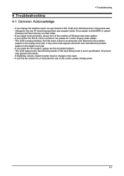
4-5 Black Screen and backlight turn on Black Screen 4 Troubleshooting Check power supply: Pin1, 2 of CN102 Yes Check pin34, 51, 66, and 82 Of U105 Yes Check pin12, 68, 97 and 117 Of U103 Yes Check Reset (pin19) Of U103 Yes Check Crystal: Pin32, Pin33 Of U103 Yes Check CCFLEnable (pin20) of U103 No MCU Fail No Power Fail No Check FB103 And U102 No Check FB105 And U106 No Check C149, R157 No Check: X1, C147, C148 Yes Check pin5 of Yes CN102 Inverter Fail No Check R127, Q101, R125, R126 4-5
4-5 Black Screen and backlight turn on Black Screen 4 Troubleshooting Check power supply: Pin1, 2 of CN102 Yes Check pin34, 51, 66, and 82 Of U105 Yes Check pin12, 68, 97 and 117 Of U103 Yes Check Reset (pin19) Of U103 Yes Check Crystal: Pin32, Pin33 Of U103 Yes Check CCFLEnable (pin20) of U103 No MCU Fail No Power Fail No Check FB103 And U102 No Check FB105 And U106 No Check C149, R157 No Check: X1, C147, C148 Yes Check pin5 of Yes CN102 Inverter Fail No Check R127, Q101, R125, R126 4-5

Service Manual
Page 55
... particular, MCU(TSUM16AL-LF) and use the SDR direct bus for the panel operating board in the LDVS formats. 5. verted to a digital value by Micom. 4. Inverter: A conversion device that are transferred to DC converting devices. Scaler: Receives the analog R,G,B signals and convert them to both MCU and Scaler at the same...
... particular, MCU(TSUM16AL-LF) and use the SDR direct bus for the panel operating board in the LDVS formats. 5. verted to a digital value by Micom. 4. Inverter: A conversion device that are transferred to DC converting devices. Scaler: Receives the analog R,G,B signals and convert them to both MCU and Scaler at the same...
Service Manual
Page 58
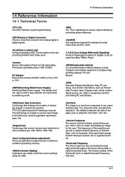
...Screen Display) Customers can easily control the screen settings using the OSD. -Dot Pitch The image on a monitor is composed of transmission method for the user. ond in order to LCD panel lamp. Unit: Hz Example: If the same light repeats itself 60 times per second. This device ... ADC, Device makes clock synchronizing HSYNC with Video clock -Inverter Device that convert various input resolution to other resolution.(ex. 640* 480 to 1024*768) -Auto Configuration(Auto adjustment) This is an algorithm to adjust monitor to optimum condition by pushing one line connecting the right edge...
...Screen Display) Customers can easily control the screen settings using the OSD. -Dot Pitch The image on a monitor is composed of transmission method for the user. ond in order to LCD panel lamp. Unit: Hz Example: If the same light repeats itself 60 times per second. This device ... ADC, Device makes clock synchronizing HSYNC with Video clock -Inverter Device that convert various input resolution to other resolution.(ex. 640* 480 to 1024*768) -Auto Configuration(Auto adjustment) This is an algorithm to adjust monitor to optimum condition by pushing one line connecting the right edge...
