Service Manual
Page 3
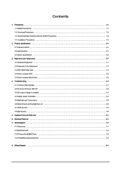
... and Adjustments ...3-1 3-1 Required Equipment ...3-1 3-2 Automatic Color Adjustment ...3-1 3-3 DDC EDID Data Input ...3-1 3-4 How to execute DDC ...3-2 3-5 How to execute MCU Code ...3-3 4. Block Diagram ...7-1 7-1 Power tree ...7-1 7-2 Mainboard part ...7-2 7-3 IP Board Part(SMPS Part) ...7-2 7-4 IP BOARD part(Inverter Part) ...7-3 8. Exploded View and Parts List ...5-1 6. Precautions ...1-1 1-1 Safety Precautions ...1-1 1-2 Servicing Precautions ...1-2 1-3 Electrostatically Sensitive Devices (ESD) Precautions 1-2 1-4 Installation Precautions ...1-3 2.
... and Adjustments ...3-1 3-1 Required Equipment ...3-1 3-2 Automatic Color Adjustment ...3-1 3-3 DDC EDID Data Input ...3-1 3-4 How to execute DDC ...3-2 3-5 How to execute MCU Code ...3-3 4. Block Diagram ...7-1 7-1 Power tree ...7-1 7-2 Mainboard part ...7-2 7-3 IP Board Part(SMPS Part) ...7-2 7-4 IP BOARD part(Inverter Part) ...7-3 8. Exploded View and Parts List ...5-1 6. Precautions ...1-1 1-1 Safety Precautions ...1-1 1-2 Servicing Precautions ...1-2 1-3 Electrostatically Sensitive Devices (ESD) Precautions 1-2 1-4 Installation Precautions ...1-3 2.
Service Manual
Page 4
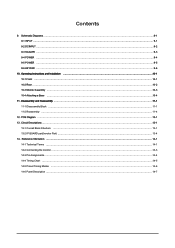
... Structure ...13-1 13-2 IP BOARD part(Inverter Part) ...13-4 14. PCB Diagram ...12-1 13. Reference Infomation ...14-1 14-1 Technical Terms ...14-1 14-2 Connecting the monitor ...14-3 14-3 Pin Assignments ...14-4 14-4 Timing Chart ...14-5 14-5 Preset Timing Modes ...14-6 14-6 Panel Description ...14-7 Schematic Diagrams ...9-1 9-1 INPUT ...9-1 9-2 DCINPUT ...9-2 9-3 SCALER ...9-3 9-4 POWER ...9-4 9-5 POWER ...9-5 9-6 KEYPAD ...9-6 10. Contents 9. Operating...
... Structure ...13-1 13-2 IP BOARD part(Inverter Part) ...13-4 14. PCB Diagram ...12-1 13. Reference Infomation ...14-1 14-1 Technical Terms ...14-1 14-2 Connecting the monitor ...14-3 14-3 Pin Assignments ...14-4 14-4 Timing Chart ...14-5 14-5 Preset Timing Modes ...14-6 14-6 Panel Description ...14-7 Schematic Diagrams ...9-1 9-1 INPUT ...9-1 9-2 DCINPUT ...9-2 9-3 SCALER ...9-3 9-4 POWER ...9-4 9-5 POWER ...9-5 9-6 KEYPAD ...9-6 10. Contents 9. Operating...
Service Manual
Page 6
For continued safety, do not attempt to modify the circuit board. 2. It is essential that service technicians have the same safety characteristics as the recommended replacement part might create shock, fire and/or other metal ... by replacing them with American National Standards Institute (ANSI C101.1, Leakage Current for higher voltage, wattage, etc. Disconnect the AC power and DC power jack before servicing. 1-1-2 Servicing the LCD Monitor 1. Inspect each lead dress to make certain that the leads are not pinched or that have special safetyrelated characteristics which are often...
For continued safety, do not attempt to modify the circuit board. 2. It is essential that service technicians have the same safety characteristics as the recommended replacement part might create shock, fire and/or other metal ... by replacing them with American National Standards Institute (ANSI C101.1, Leakage Current for higher voltage, wattage, etc. Disconnect the AC power and DC power jack before servicing. 1-1-2 Servicing the LCD Monitor 1. Inspect each lead dress to make certain that the leads are not pinched or that have special safetyrelated characteristics which are often...
Service Manual
Page 7
... of the AC plug and accessible conductive parts (see above the printed circuit board for safety. Some solder removal devices not classified as aluminum foil to prevent ... Reinstall all other conductive materials. 7. Connect an insulation resistance meter (500 V) to the monitor. 2. The following servicing precautions and any of the safety precautions, always follow the Safety ... covered by static electricity. These can be sure to remove the wrist strap before applying power to the blades of this service manual, read and follow the safety precautions. 1-2-1 General...
... of the AC plug and accessible conductive parts (see above the printed circuit board for safety. Some solder removal devices not classified as aluminum foil to prevent ... Reinstall all other conductive materials. 7. Connect an insulation resistance meter (500 V) to the monitor. 2. The following servicing precautions and any of the safety precautions, always follow the Safety ... covered by static electricity. These can be sure to remove the wrist strap before applying power to the blades of this service manual, read and follow the safety precautions. 1-2-1 General...
Service Manual
Page 48
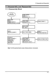
11 Disassembly and Reassembly 11-1 Disassembly Block 11 Disassembly and Reassembly LE 1729 LCD Monitor ASSY, BASE BASE*1 RUBBER FOOT *6 SCREW.P.CROSS,T.T-4*8,Zn STAND_REAR*1 HINGE *1 SCREW M4*10 *3 ASSY STAND SCREW M4*10 *4 BACK COVER BKT-VESA *4 LENS*1 CONTROL BOARD*1 ASSY FRONT BEZEL STAND_FRONT *1 BEZEL*1 BUTTON,FUNCTION *1 CHASSIS *1 PCBA I/F BOARD *1 Power Board *1 SCREW M3*6 CLIP,WIRE *1 SHIELING*1 ASSY PANEL*1 SCREW M3*5, *4 CABLE 30P FFC BOLT,#4-40*11.8,Ni *2 INNOLUX PANEL EN01 Note: The DIS assembly direction please following direction of arrowhead 11-1
11 Disassembly and Reassembly 11-1 Disassembly Block 11 Disassembly and Reassembly LE 1729 LCD Monitor ASSY, BASE BASE*1 RUBBER FOOT *6 SCREW.P.CROSS,T.T-4*8,Zn STAND_REAR*1 HINGE *1 SCREW M4*10 *3 ASSY STAND SCREW M4*10 *4 BACK COVER BKT-VESA *4 LENS*1 CONTROL BOARD*1 ASSY FRONT BEZEL STAND_FRONT *1 BEZEL*1 BUTTON,FUNCTION *1 CHASSIS *1 PCBA I/F BOARD *1 Power Board *1 SCREW M3*6 CLIP,WIRE *1 SHIELING*1 ASSY PANEL*1 SCREW M3*5, *4 CABLE 30P FFC BOLT,#4-40*11.8,Ni *2 INNOLUX PANEL EN01 Note: The DIS assembly direction please following direction of arrowhead 11-1

Service Manual
Page 54
... depending on the panel manufacturer) 17" : 4*(7.0mA*650Vrms)=4* 4.55W=18.2W 2.2 The power consumption of the Panel Control board is as follows: 5V*645mA=3.23W 2.3 The power consumption of . 1.2 The Scaler consumes power up to 37mA 1.3 The power to the panel is as follows: 3.3V*204mA + 1.8V*145mA = 0.93W 13-1... When the AD board is in DPMS state: 1.1 The IP has been designed so that it operates with a power consumption of less than ...
... depending on the panel manufacturer) 17" : 4*(7.0mA*650Vrms)=4* 4.55W=18.2W 2.2 The power consumption of the Panel Control board is as follows: 5V*645mA=3.23W 2.3 The power consumption of . 1.2 The Scaler consumes power up to 37mA 1.3 The power to the panel is as follows: 3.3V*204mA + 1.8V*145mA = 0.93W 13-1... When the AD board is in DPMS state: 1.1 The IP has been designed so that it operates with a power consumption of less than ...

Service Manual
Page 55
...of two lines that converts DC rated voltage/current to high ones necessary for the panel operating board in normal conditions. or down- Scaler & EEPROM: I2C is a two-way serial bus of Power MosFET is transferred into ADC input port of the chip. Function Key: A certain keystroke ... supports communications across the integrated circuits as well as between FLASH and EEPROM. The IP board receives 5V and outputs 1.8 or 3.3V that are transferred to the scaler (TSUM16AL-LF). 3. Power MosFET: The IP board receives 5V and outputs a lower voltage in the LDVS formats. 5. pared to which...
...of two lines that converts DC rated voltage/current to high ones necessary for the panel operating board in normal conditions. or down- Scaler & EEPROM: I2C is a two-way serial bus of Power MosFET is transferred into ADC input port of the chip. Function Key: A certain keystroke ... supports communications across the integrated circuits as well as between FLASH and EEPROM. The IP board receives 5V and outputs 1.8 or 3.3V that are transferred to the scaler (TSUM16AL-LF). 3. Power MosFET: The IP board receives 5V and outputs a lower voltage in the LDVS formats. 5. pared to which...
User Guide
Page 33
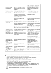
...of the video card signals. There are properly connected to the computer. 2. If you installed the monitor driver? Is the screen displaying only one color as if looking at the video card. (Refer to...to a crash between applications? Unlock the OSD by pressing the [MENU / ] button for the main board of the video screen is fully inserted in Safe Mode, remove the Display Adapter at 56 Hz ~ ... to reinstall the adapter (video) driver. Set the video card by referring to the monitor? Check if the power cord and the video cables are only 16 colors shown on the screen. The screen...
...of the video card signals. There are properly connected to the computer. 2. If you installed the monitor driver? Is the screen displaying only one color as if looking at the video card. (Refer to...to a crash between applications? Unlock the OSD by pressing the [MENU / ] button for the main board of the video screen is fully inserted in Safe Mode, remove the Display Adapter at 56 Hz ~ ... to reinstall the adapter (video) driver. Set the video card by referring to the monitor? Check if the power cord and the video cables are only 16 colors shown on the screen. The screen...


