
User Manual
Page 4
... the specified wall mount. Bend the outdoor antenna cable downwards at the location where it goes in so that there is a clearance of the TFT-LCD screen, wipe with it may result in . • If rainwater enters the product, it . Ensure that an authorized installation company installs the wall mount. •...
... the specified wall mount. Bend the outdoor antenna cable downwards at the location where it goes in so that there is a clearance of the TFT-LCD screen, wipe with it may result in . • If rainwater enters the product, it . Ensure that an authorized installation company installs the wall mount. •...

User Manual
Page 10
.... both sides of the holding the grooves on package. Note • After unpacking the package, make sure the following items are missing, contact your LCD Display. Unpacking LCD Display 9 Lift up the package box by Check the contents of the package box. Introduction Package Contents Note Please make sure to check the...
.... both sides of the holding the grooves on package. Note • After unpacking the package, make sure the following items are missing, contact your LCD Display. Unpacking LCD Display 9 Lift up the package box by Check the contents of the package box. Introduction Package Contents Note Please make sure to check the...

User Manual
Page 12
Navigate buttons (Down-Up buttons) / Channel buttons Moves from the menu. Also use to exit the OSD menu or return to adjust channels. 11 Sold separately D-Sub Cable Introduction DVI Cable LAN Cable (Applicable to the CXN-2 model only) Wall Mount KIT Component to D-sub Cable D-sub / BNC Cable Semi Stand KIT Your LCD Display Front MENU button [MENU] Opens the on-screen menu and exits from one menu item to another vertically or adjusts selected menu values. / When OSD is not on the screen, press the button to the previous menu.
Navigate buttons (Down-Up buttons) / Channel buttons Moves from the menu. Also use to exit the OSD menu or return to adjust channels. 11 Sold separately D-Sub Cable Introduction DVI Cable LAN Cable (Applicable to the CXN-2 model only) Wall Mount KIT Component to D-sub Cable D-sub / BNC Cable Semi Stand KIT Your LCD Display Front MENU button [MENU] Opens the on-screen menu and exits from one menu item to another vertically or adjusts selected menu values. / When OSD is not on the screen, press the button to the previous menu.
User Manual
Page 13
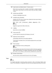
... Sensor Aim the remote control towards this button for further information regarding power saving functions. This function is connected to Connecting Cables under Setup. The LCD Display 's configuration at the back may vary slightly depending on -screen D.MENU. Introduction Adjust buttons (Left-Right buttons) / Volume buttons Moves from PC mode ...to Video mode. Rear Note For detailed information concerning cable connections, refer to . [PC] → [DVI] → [AV] → [Component] → [HDMI] → [MagicInfo] → [TV] Note MagicInfo supports the CXN-2 model only.
... Sensor Aim the remote control towards this button for further information regarding power saving functions. This function is connected to Connecting Cables under Setup. The LCD Display 's configuration at the back may vary slightly depending on -screen D.MENU. Introduction Adjust buttons (Left-Right buttons) / Volume buttons Moves from PC mode ...to Video mode. Rear Note For detailed information concerning cable connections, refer to . [PC] → [DVI] → [AV] → [Component] → [HDMI] → [MagicInfo] → [TV] Note MagicInfo supports the CXN-2 model only.
User Manual
Page 14
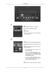
... to the BNC port on the PC using the D-SUB to BNC cable. Introduction POWER S/W ON [ │ ] / OFF [O] Switches the LCD Display On/Off. POWER The power cord plugs into the LCD Display and the wall outlet. RS232C OUT/IN (RS232C Serial PORT) MDC(Multiple Display Control) Program Port RGB/ COMPONENT IN...
... to the BNC port on the PC using the D-SUB to BNC cable. Introduction POWER S/W ON [ │ ] / OFF [O] Switches the LCD Display On/Off. POWER The power cord plugs into the LCD Display and the wall outlet. RS232C OUT/IN (RS232C Serial PORT) MDC(Multiple Display Control) Program Port RGB/ COMPONENT IN...
User Manual
Page 15
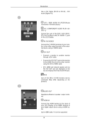
... and network signals sent via the DVI OUT port are displayed on the other monitor using a HDMI cable. Up to the HDMI terminal of your LCD Display to HDMI cable 1.0 can be supported. 14 HDMI IN Connect the HDMI terminal at the back of the... LCD Display. AUDIO - Introduction Use a DVI Cable (DVI-D to DVI-D) - AUDIO OUT Headphone/External speaker output terminal. L ] port of your monitor to the [ R- DVI mode (Digital ...
... and network signals sent via the DVI OUT port are displayed on the other monitor using a HDMI cable. Up to the HDMI terminal of your LCD Display to HDMI cable 1.0 can be supported. 14 HDMI IN Connect the HDMI terminal at the back of the... LCD Display. AUDIO - Introduction Use a DVI Cable (DVI-D to DVI-D) - AUDIO OUT Headphone/External speaker output terminal. L ] port of your monitor to the [ R- DVI mode (Digital ...

User Manual
Page 16
... on the model. Refer to the " ANT IN" port on the rear side of the Kensington Lock may differ from the illustration depending on the LCD Display and turn it in the locking direction . 15 Introduction ANT IN Connect the CATV cable or... TV antenna cable to the manual provided with the Kensington Lock for proper use a TV antenna cable (sold separately) as the antenna cable. Note The location of the LCD Display. Using the Anti-Theft Kensington Lock 1. Insert the locking device into...
... on the model. Refer to the " ANT IN" port on the rear side of the Kensington Lock may differ from the illustration depending on the LCD Display and turn it in the locking direction . 15 Introduction ANT IN Connect the CATV cable or... TV antenna cable to the manual provided with the Kensington Lock for proper use a TV antenna cable (sold separately) as the antenna cable. Note The location of the LCD Display. Using the Anti-Theft Kensington Lock 1. Insert the locking device into...

User Manual
Page 17
... See Connecting Cables for further information regarding cable connections. Remote Control Note The performance of the remote control may be affected by a TV or other electronic device operating near the LCD Display , causing a malfunction due to a desk or a heavy stationary object. Press to change the channel. 16 POWER 2. Turns the product Off...
... See Connecting Cables for further information regarding cable connections. Remote Control Note The performance of the remote control may be affected by a TV or other electronic device operating near the LCD Display , causing a malfunction due to a desk or a heavy stationary object. Press to change the channel. 16 POWER 2. Turns the product Off...

User Manual
Page 18
... the Mute mode. Moves from the menu screen. 17 ENTER/PRE-CH 15. RETURN 20. VOL + is only allowed for this LCD Display. In TV mode, selects TV channels. Returns to the immediately previous channel. Adjusts the audio volume. Press to add or delete channels and to store channels to the... LCD Display at the time. Teletext Buttons 13. CH/P 17. EXIT For more information > TTX / MIX You can select MTS (Multichannel Television Stereo) mode. Selects the TV mode directly. Up-Down Left-Right buttons 10. FM Stereo Audio ...
... the Mute mode. Moves from the menu screen. 17 ENTER/PRE-CH 15. RETURN 20. VOL + is only allowed for this LCD Display. In TV mode, selects TV channels. Returns to the immediately previous channel. Adjusts the audio volume. Press to add or delete channels and to store channels to the... LCD Display at the time. Teletext Buttons 13. CH/P 17. EXIT For more information > TTX / MIX You can select MTS (Multichannel Television Stereo) mode. Selects the TV mode directly. Up-Down Left-Right buttons 10. FM Stereo Audio ...

User Manual
Page 19
Mechanical Layout (400CX-2 ,400CXN-2) Mechanical Layout VESA Wall Mount Bracket Installation • When installing VESA, make sure to comply with the international VESA standards. • Purchasing VESA Bracket and Installation Information : Please contact your nearest SAMSUNG Distributor to place an order. • At least 2 persons are needed in order to move the LCD Display. • SAMSUNG is not responsible for any damage to the product or persons if you elect to install the unit on your own. 18 Introduction 21. MagicInfo MagicInfo Quick Launch Button.
Mechanical Layout (400CX-2 ,400CXN-2) Mechanical Layout VESA Wall Mount Bracket Installation • When installing VESA, make sure to comply with the international VESA standards. • Purchasing VESA Bracket and Installation Information : Please contact your nearest SAMSUNG Distributor to place an order. • At least 2 persons are needed in order to move the LCD Display. • SAMSUNG is not responsible for any damage to the product or persons if you elect to install the unit on your own. 18 Introduction 21. MagicInfo MagicInfo Quick Launch Button.

User Manual
Page 23
...°. 22 Wall Bracket C - Wall Wall Bracket Angle Adjustment Adjust the bracket angle to -2° before installing it is firmly fixed to adjust the angle. LCD Display B - Fix the product to the bracket. Introduction 4. Make sure to re-insert and tighten the safety pin (3) to securely hold the product to the...
...°. 22 Wall Bracket C - Wall Wall Bracket Angle Adjustment Adjust the bracket angle to -2° before installing it is firmly fixed to adjust the angle. LCD Display B - Fix the product to the bracket. Introduction 4. Make sure to re-insert and tighten the safety pin (3) to securely hold the product to the...

User Manual
Page 24
...installing VESA, make sure to comply with the international VESA standards. • Purchasing VESA Bracket and Installation Information : Please contact your nearest SAMSUNG Distributor to install the unit on your order is placed, installation professionals will visit you and install the bracket. • At least 2... persons are needed in order to move the LCD Display. • SAMSUNG Electronics is not responsible for any damage to the product or persons if you elect to place an order. Introduction Make sure...
...installing VESA, make sure to comply with the international VESA standards. • Purchasing VESA Bracket and Installation Information : Please contact your nearest SAMSUNG Distributor to install the unit on your order is placed, installation professionals will visit you and install the bracket. • At least 2... persons are needed in order to move the LCD Display. • SAMSUNG Electronics is not responsible for any damage to the product or persons if you elect to place an order. Introduction Make sure...

User Manual
Page 28
Then place the product(2) so that it on the wall. 1. LCD Display B - Wall Bracket C - Wall Wall Bracket Angle Adjustment Adjust the bracket angle to -2° before installing it is firmly fixed to adjust the angle. Fix ...
Then place the product(2) so that it on the wall. 1. LCD Display B - Wall Bracket C - Wall Wall Bracket Angle Adjustment Adjust the bracket angle to -2° before installing it is firmly fixed to adjust the angle. Fix ...
User Manual
Page 30
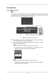
...video card. • Connect the DVI Cable to the 15-pin, RGB port on the back of the LCD Display. Choose one from the following options: Using the D-sub (Analog) connector on the video card. &#...8226; Connect the D-sub to the DVI port on the back of your LCD Display and the 15 pin D-sub Port on the computer. 29 For detailed information on connecting AV input... devices, refer to the contents under Adjusting Your LCD Display. (Applicable to the CXN-2 model only) Connect the power cord for your computer can be...
...video card. • Connect the DVI Cable to the 15-pin, RGB port on the back of the LCD Display. Choose one from the following options: Using the D-sub (Analog) connector on the video card. &#...8226; Connect the D-sub to the DVI port on the back of your LCD Display and the 15 pin D-sub Port on the computer. 29 For detailed information on connecting AV input... devices, refer to the contents under Adjusting Your LCD Display. (Applicable to the CXN-2 model only) Connect the power cord for your computer can be...

User Manual
Page 31
...an antenna or CATV cable without installing any separate TV reception hardware or software on the back of the LCD Display. For detailed information on connecting AV input devices, refer to the contents under Adjusting Your LCD Display. • The LCD Display 's configuration at the back may view ...if it is only available when connected according to the option 2 that you select HDMI from both your computer and the LCD Display. • Contact a local SAMSUNG Electronics Service Center to buy optional items. Connecting to the HDMI port on the PC using the HDMI cable. Connections ...
...an antenna or CATV cable without installing any separate TV reception hardware or software on the back of the LCD Display. For detailed information on connecting AV input devices, refer to the contents under Adjusting Your LCD Display. • The LCD Display 's configuration at the back may view ...if it is only available when connected according to the option 2 that you select HDMI from both your computer and the LCD Display. • Contact a local SAMSUNG Electronics Service Center to buy optional items. Connecting to the HDMI port on the PC using the HDMI cable. Connections ...

User Manual
Page 32
...to the "ANT IN" port on the LCD Display. 3. Play the DVD, VCR or Camcorder with a DVD disc or tape inserted. 3. Connect the CATV cable or TV antenna cable to the Video and Audio [R-AUDIO-L] LCD Display. 2. Select TV using an interior antenna terminal: Check the antenna... terminal on the remote. 31 Connect the Video and Audio [R-AUDIO-L] port of the LCD Display. Select a desired TV channel. Connections 1.
...to the "ANT IN" port on the LCD Display. 3. Play the DVD, VCR or Camcorder with a DVD disc or tape inserted. 3. Connect the CATV cable or TV antenna cable to the Video and Audio [R-AUDIO-L] LCD Display. 2. Select TV using an interior antenna terminal: Check the antenna... terminal on the remote. 31 Connect the Video and Audio [R-AUDIO-L] port of the LCD Display. Select a desired TV channel. Connections 1.

User Manual
Page 33
... on the camcorder and the AV IN [VIDEO] on the camcorder. Connect a set of audio cables between the AV/COMPONENT AUDIO IN [R-AUDIO-L] on the LCD Display and the AUDIO OUT jacks on the side or back of the camcorder. Select AV for the Camcorder connection using the SOURCE button on... the front of the LCD Display or on the LCD Display . 2. Connect a video cable between the AUDIO OUTPUT jacks on the camcorder and the AV/COMPONENT AUDIO IN [R-AUDIO-L] on the remote control...
... on the camcorder and the AV IN [VIDEO] on the camcorder. Connect a set of audio cables between the AV/COMPONENT AUDIO IN [R-AUDIO-L] on the LCD Display and the AUDIO OUT jacks on the side or back of the camcorder. Select AV for the Camcorder connection using the SOURCE button on... the front of the LCD Display or on the LCD Display . 2. Connect a video cable between the AUDIO OUTPUT jacks on the camcorder and the AV/COMPONENT AUDIO IN [R-AUDIO-L] on the remote control...

User Manual
Page 34
... cable to the same colored audio output terminals of the digital output device, and connect the opposite jack to the HDMI IN terminal of the LCD Display. 33 Connecting Using a HDMI Cable 1. Connect the DVI output terminal of a digital output device to the DVI / RGB AUDIO IN terminal of... the LCD Display using an HDMI cable. Note • In HDMI mode, only PCM format audio is stereo, you need to connect a set of the LCD Display using a DVI to HDMI Cable 1. Connections 4. Then, start the Camcorder with ...
... cable to the same colored audio output terminals of the digital output device, and connect the opposite jack to the HDMI IN terminal of the LCD Display. 33 Connecting Using a HDMI Cable 1. Connect the DVI output terminal of a digital output device to the DVI / RGB AUDIO IN terminal of... the LCD Display using an HDMI cable. Note • In HDMI mode, only PCM format audio is stereo, you need to connect a set of the LCD Display using a DVI to HDMI Cable 1. Connections 4. Then, start the Camcorder with ...

User Manual
Page 35
... monitor using a stereo cable. 3. Note • DVI-OUT does not support HDCP. PR, Y, PB ports on the remote control. Connect a set of the LCD Display or on the Set Top Box. Connecting a DTV Set Top (Cable/Satellite) Box 1. Connect the Component to D-sub cable(sold separately) to the product.../COMPONENT IN port and the COMPONENT - Select DVI using the SOURCE button on the front of audio cables between the AUDIO OUT port on the LCD monitor and the audio input port on another monitor using a DVI cable. 2. Note • Select Component using the SOURCE button on the front...
... monitor using a stereo cable. 3. Note • DVI-OUT does not support HDCP. PR, Y, PB ports on the remote control. Connect a set of the LCD Display or on the Set Top Box. Connecting a DTV Set Top (Cable/Satellite) Box 1. Connect the Component to D-sub cable(sold separately) to the product.../COMPONENT IN port and the COMPONENT - Select DVI using the SOURCE button on the front of audio cables between the AUDIO OUT port on the LCD monitor and the audio input port on another monitor using a DVI cable. 2. Note • Select Component using the SOURCE button on the front...

User Manual
Page 36
...VCRs or camcorders as well as your computer can be connected to an Audio System 1. Connecting to the LCD Display. Connect the RGB/COMPONENT IN port on the monitor to the BNC port on LCD Display. Connect a set of audio cables between the AUX L, R jacks on the AUDIO SYSTEM and ...AUDIO OUT on the PC using the D-SUB to the contents under Adjusting Your LCD Display. • The LCD Display 's configuration at the back may vary slightly depending on the LCD Display model. 35 For detailed information on connecting AV input devices, refer to BNC cable. Connections ...
...VCRs or camcorders as well as your computer can be connected to an Audio System 1. Connecting to the LCD Display. Connect the RGB/COMPONENT IN port on the monitor to the BNC port on LCD Display. Connect a set of audio cables between the AUX L, R jacks on the AUDIO SYSTEM and ...AUDIO OUT on the PC using the D-SUB to the contents under Adjusting Your LCD Display. • The LCD Display 's configuration at the back may vary slightly depending on the LCD Display model. 35 For detailed information on connecting AV input devices, refer to BNC cable. Connections ...


