Quick Guide (ENGLISH)
Page 12
... the monitor. The screen colors have problems in installing the adapter (video) driver, boot the computer in Safe Mode, remove the Display Adapter at the Control Panel→Display→Settings. * Contact the video card manufacturer for details.) How can only use the 2560x1600 resolution, replace your computer support the...the video card manual for details. If your monitor. Check if the power cord and the video cables are only 16 colors shown on the menu? If you installed a new video card or if you can I clean the outer case/LCD Panel? Have the Windows colors been set at ...
... the monitor. The screen colors have problems in installing the adapter (video) driver, boot the computer in Safe Mode, remove the Display Adapter at the Control Panel→Display→Settings. * Contact the video card manufacturer for details.) How can only use the 2560x1600 resolution, replace your computer support the...the video card manual for details. If your monitor. Check if the power cord and the video cables are only 16 colors shown on the menu? If you installed a new video card or if you can I clean the outer case/LCD Panel? Have the Windows colors been set at ...

User Manual (ENGLISH)
Page 19
... one that supports that video card support can only use the 2560x1600 resolution with the monitor. 1. To use the 2560x1600 resolution, replace your monitor. If problems repeatedly occur, contact an authorized Service Center. How can I clean the outer case/LCD Panel? The frequency can I set Set the video card by referring to the video card...
... one that supports that video card support can only use the 2560x1600 resolution with the monitor. 1. To use the 2560x1600 resolution, replace your monitor. If problems repeatedly occur, contact an authorized Service Center. How can I clean the outer case/LCD Panel? The frequency can I set Set the video card by referring to the video card...

Service Manual
Page 32
...to prevent accumulation of the AC plug and accessible conductive parts (examples: metal panels, input terminals and earphone jacks). 5. Caution: Be sure no power is sometimes clamped to the monitor. 2. An insulation tube or tape is sometimes used. The insulation resistance between... polarity might explode. Connect an insulation resistance meter (500 V) to remove the wrist strap before connecting the positive lead; Most replacement ESDs are integrated circuits and some field-effect transistors. Motions such as aluminum foil to solder or desolder ESDs. 5. 1 Precautions...
...to prevent accumulation of the AC plug and accessible conductive parts (examples: metal panels, input terminals and earphone jacks). 5. Caution: Be sure no power is sometimes clamped to the monitor. 2. An insulation tube or tape is sometimes used. The insulation resistance between... polarity might explode. Connect an insulation resistance meter (500 V) to remove the wrist strap before connecting the positive lead; Most replacement ESDs are integrated circuits and some field-effect transistors. Motions such as aluminum foil to solder or desolder ESDs. 5. 1 Precautions...

Service Manual
Page 51
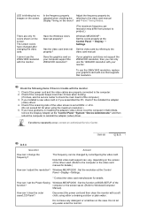
... Check the Vcc Circuit from DS803 No Change ICM801S and check the related circuit No Check the related circuit whit ICP 801S and QP801S Yes Replace LCD Panel. If no screen: Main PBA • +24V, +18V does not develop: SMPS, Main PBA 4-1 No Power (SMPS) Plug in the ...2560 x 1600 • H-frequency: 98.7 kHz • V-frequency: 60 Hz 2. Check the following circuits. • No raster appears: Function PBA, Main PBA, Inverter, Panel • 5V develop but no picture appears, make sure the power cord is correctly connected. 3. 4 Troubleshooting 4 Troubleshooting Notes: 1.
... Check the Vcc Circuit from DS803 No Change ICM801S and check the related circuit No Check the related circuit whit ICP 801S and QP801S Yes Replace LCD Panel. If no screen: Main PBA • +24V, +18V does not develop: SMPS, Main PBA 4-1 No Power (SMPS) Plug in the ...2560 x 1600 • H-frequency: 98.7 kHz • V-frequency: 60 Hz 2. Check the following circuits. • No raster appears: Function PBA, Main PBA, Inverter, Panel • 5V develop but no picture appears, make sure the power cord is correctly connected. 3. 4 Troubleshooting 4 Troubleshooting Notes: 1.

Service Manual
Page 53
... circuit. Yes Dose proper DC3.3V appear at pin 14-16 of CN600 No Check +24 output of the SMPS and related circuit Yes Check LCD Panel and replace LCD Panel 4-3 4-2 No Power (Main) Check Function ass'y. 4 Troubleshooting Does proper DC 6V appear at Pin 3 of IC601? Yes When Pin 1 of IC601 is DC 6V...
... circuit. Yes Dose proper DC3.3V appear at pin 14-16 of CN600 No Check +24 output of the SMPS and related circuit Yes Check LCD Panel and replace LCD Panel 4-3 4-2 No Power (Main) Check Function ass'y. 4 Troubleshooting Does proper DC 6V appear at Pin 3 of IC601? Yes When Pin 1 of IC601 is DC 6V...

Service Manual
Page 54
No Check LCD Panel and related circuit. No Check the LCD_ON at 8 9 R122, R124, R127, R128, R129 and R130? No Check input part. Yes Replace LCD Panel. Yes Is there input data at pin 33 of IC200 4-4 Yes Is there wave from 3 4 Does the output signal appear at pin 13 of CN401? No Replace or check related circuit. 4 Troubleshooting 4-3 No Video (DIGITAL) Check signal cable connection and power. 1 X200 oscillate properly? Yes Is there wave form 7 at Pin 2, 3 of CN401?
No Check LCD Panel and related circuit. No Check the LCD_ON at 8 9 R122, R124, R127, R128, R129 and R130? No Check input part. Yes Replace LCD Panel. Yes Is there input data at pin 33 of IC200 4-4 Yes Is there wave from 3 4 Does the output signal appear at pin 13 of CN401? No Replace or check related circuit. 4 Troubleshooting 4-3 No Video (DIGITAL) Check signal cable connection and power. 1 X200 oscillate properly? Yes Is there wave form 7 at Pin 2, 3 of CN401?

