Service Manual
Page 2
... ...5 1-3 Static Electricity Precautions ...5 1-4 Installation Precautions ...6 2. Schematic Diagrams ...27 8-1 DC- Exploded View and Parts List ...20 5-1 Exploded View ...20 5-2 Parts List ...22 6. Operating instructions and installation ...31 9-1 front ...31 9-2 ...Rear ...32 2 Block Diagram ...24 6-1 Power Tree ...24 6-2 Main Board Part ...24 6-3 IP Board Part (SMPS Part) ...25 6-4 IP Board Part (Inverter Part) ...25 7. Product specifications ...7 2-1 Fashion Feature ...7 2-2 2220WM...
... ...5 1-3 Static Electricity Precautions ...5 1-4 Installation Precautions ...6 2. Schematic Diagrams ...27 8-1 DC- Exploded View and Parts List ...20 5-1 Exploded View ...20 5-2 Parts List ...22 6. Operating instructions and installation ...31 9-1 front ...31 9-2 ...Rear ...32 2 Block Diagram ...24 6-1 Power Tree ...24 6-2 Main Board Part ...24 6-3 IP Board Part (SMPS Part) ...25 6-4 IP Board Part (Inverter Part) ...25 7. Product specifications ...7 2-1 Fashion Feature ...7 2-2 2220WM...
Service Manual
Page 3
Circuit Descriptions ...42 12-1 Overall Block Structture ...42 12-2 IP Board Part (Power) Schematic Diagrams ...44 12-3 IP Board (Inverter) Schematic Diagrams ...45 13. PCB Diagram ...40 11-1 Mian Board...40 12-2 Power Board...41 12. Reference Information ...46 13-1 Technical Terms ...46 13-2 Pin Assignments ...48 13-3 Timing Chart ...49 3 Disassembly and Reassembly ...36 10-1 Disassembly ...36 10-2 Assembly Block ...39 11. 9-3 Connecting the monitor ...33 9-4 Monitor Assembly ... 34 9-5 Attaching a Base ... 35 10.
Circuit Descriptions ...42 12-1 Overall Block Structture ...42 12-2 IP Board Part (Power) Schematic Diagrams ...44 12-3 IP Board (Inverter) Schematic Diagrams ...45 13. PCB Diagram ...40 11-1 Mian Board...40 12-2 Power Board...41 12. Reference Information ...46 13-1 Technical Terms ...46 13-2 Pin Assignments ...48 13-3 Timing Chart ...49 3 Disassembly and Reassembly ...36 10-1 Disassembly ...36 10-2 Assembly Block ...39 11. 9-3 Connecting the monitor ...33 9-4 Monitor Assembly ... 34 9-5 Attaching a Base ... 35 10.
Service Manual
Page 4
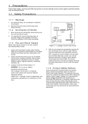
... may not be obtained by on schematics and parts lists. With the unit's AC switch first in the monitor. 2. A substitute replacement that complies with components rated for Appliances), and Underwriters Laboratories (UL Publication UL1410, 59.7). Disconnect the AC power and DC power jack before servicing. 1-1-2 Servicing the LCD Monitor 1. With the unit completely reassembled...
... may not be obtained by on schematics and parts lists. With the unit's AC switch first in the monitor. 2. A substitute replacement that complies with components rated for Appliances), and Underwriters Laboratories (UL Publication UL1410, 59.7). Disconnect the AC power and DC power jack before servicing. 1-1-2 Servicing the LCD Monitor 1. With the unit completely reassembled...
Service Manual
Page 43
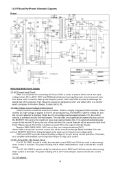
12-2 IP Board Part(Power) Schematic Diagrams Power Switching Mode Power Supply 1.1 AC Current Input Circuit P801 is a highly integrated PWM controller. L801 is used to smooth the current waves. C801 ...
12-2 IP Board Part(Power) Schematic Diagrams Power Switching Mode Power Supply 1.1 AC Current Input Circuit P801 is a highly integrated PWM controller. L801 is used to smooth the current waves. C801 ...


