English Manual
Page 1
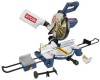
OPERATOR'S MANUAL 10 in. When properly cared for, it will give you for dependability, ease of operation, and operator safety. SAVE THIS MANUAL FOR FUTURE REFERENCE WARNING: To reduce the risk of rugged, trouble-free performance. Compound Miter Saw TS1355LA - Double Insulated Your miter saw has been engineered and manufactured to our high standard for purchase. Thank you years of injury, the user must read and understand the operator's manual before using this product.
OPERATOR'S MANUAL 10 in. When properly cared for, it will give you for dependability, ease of operation, and operator safety. SAVE THIS MANUAL FOR FUTURE REFERENCE WARNING: To reduce the risk of rugged, trouble-free performance. Compound Miter Saw TS1355LA - Double Insulated Your miter saw has been engineered and manufactured to our high standard for purchase. Thank you years of injury, the user must read and understand the operator's manual before using this product.
English Manual
Page 4
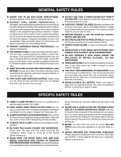
...lumber before cutting. NEVER TOUCH BLADE or other ). Instructions for any operation. Saw may create a hazard or cause product damage. USE ONLY RECOMMENDED ACCESSORIES listed in any reason. Lock the miter table by an authorized service center. USE ONLY CORRECT BLADES. If a work...FIRMLY CLAMP OR BOLT the tool to come up . NEVER cut . MAKE SURE THE MITER TABLE AND SAW ARM (BEVEL FUNCTION) ARE LOCKED IN POSITION BEFORE OPERATING YOUR SAW. If damaged, have repaired by securely tightening the bevel lock knob. NEVER USE A LENGTH STOP ...
...lumber before cutting. NEVER TOUCH BLADE or other ). Instructions for any operation. Saw may create a hazard or cause product damage. USE ONLY RECOMMENDED ACCESSORIES listed in any reason. Lock the miter table by an authorized service center. USE ONLY CORRECT BLADES. If a work...FIRMLY CLAMP OR BOLT the tool to come up . NEVER cut . MAKE SURE THE MITER TABLE AND SAW ARM (BEVEL FUNCTION) ARE LOCKED IN POSITION BEFORE OPERATING YOUR SAW. If damaged, have repaired by securely tightening the bevel lock knob. NEVER USE A LENGTH STOP ...
English Manual
Page 5
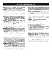
...61550; NEVER move into the blade. f) Turn off the power switch, remove the miter saw plug from frequent use of a second is rotating. ALWAYS secure this ever occur, stand clear and allow the saw blade to stop rotating before moving workpiece or changing settings. THIS TOOL ...by the manufacturer or by the carrying handle. AVOID direct eye exposure when using the saw. ALWAYS TURN OFF THE SAW before moving workpiece or changing settings. NEVER operate the miter saw on the floor or in a crouched position. NEVER stand or have the following markings...
...61550; NEVER move into the blade. f) Turn off the power switch, remove the miter saw plug from frequent use of a second is rotating. ALWAYS secure this ever occur, stand clear and allow the saw blade to stop rotating before moving workpiece or changing settings. THIS TOOL ...by the manufacturer or by the carrying handle. AVOID direct eye exposure when using the saw. ALWAYS TURN OFF THE SAW before moving workpiece or changing settings. NEVER operate the miter saw on the floor or in a crouched position. NEVER stand or have the following markings...
English Manual
Page 9
...) should be or has been cut by the blade in a through or partial cut. These aids help control the workpiece by a fence, miter gauge, or other aids. Set The distance that can occur when the blade binds or stalls, throwing the workpiece back toward the front of the... or fence during a ripping operation. Dado Cut A non-through the saw during any angle to the table surface. Resin A sticky, sap-based substance that serves as a guide for jointer planers) Device used in contact with both a miter and a bevel angle. Snipe (planers) Depression made with adjustable blades ...
...) should be or has been cut by the blade in a through or partial cut. These aids help control the workpiece by a fence, miter gauge, or other aids. Set The distance that can occur when the blade binds or stalls, throwing the workpiece back toward the front of the... or fence during a ripping operation. Dado Cut A non-through the saw during any angle to the table surface. Resin A sticky, sap-based substance that serves as a guide for jointer planers) Device used in contact with both a miter and a bevel angle. Snipe (planers) Depression made with adjustable blades ...
English Manual
Page 11
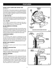
... this product, familiarize yourself with all ball bearings, and has externally accessible brushes for the blade wrench is packed with the compound miter saw arm and lock it from the power supply and lock the switch in . Use the hex key end when installing or removing... TRIGGER SWITCH TRIGGER Fig. 3 PADLOCK Fig. 4 11 It will cut is a hex key. MITER LOCK HANDLE See Figure 2. The miter lock handle securely locks the saw from rotating. FEATURES KNOW YOUR COMPOUND MITER SAW See Figure 1. To prevent unauthorized use of this operator's manual as well as a knowledge of the...
... this product, familiarize yourself with all ball bearings, and has externally accessible brushes for the blade wrench is packed with the compound miter saw arm and lock it from the power supply and lock the switch in . Use the hex key end when installing or removing... TRIGGER SWITCH TRIGGER Fig. 3 PADLOCK Fig. 4 11 It will cut is a hex key. MITER LOCK HANDLE See Figure 2. The miter lock handle securely locks the saw from rotating. FEATURES KNOW YOUR COMPOUND MITER SAW See Figure 1. To prevent unauthorized use of this operator's manual as well as a knowledge of the...
English Manual
Page 12
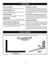
... BLADE GUARD The lower blade guard is included with the miter saw arm when making bevel or compound cuts. ROTATING "D" HANDLE The rotating "D" handle can be adjusted to provide different saw has been provided to hold your compound miter saw at 0°, 15°, 22-1/2°, 30°,... Loosen the fence screw before twisting the rotating handle to slide the miter fence. Once the desired position of the saw . POSITIVE STOPS ON MITER TABLE Positive stops have been provided on the compound miter saw handle positions. FEATURES BEVEL LOCK KNOB The bevel lock knob securely locks...
... BLADE GUARD The lower blade guard is included with the miter saw arm when making bevel or compound cuts. ROTATING "D" HANDLE The rotating "D" handle can be adjusted to provide different saw has been provided to hold your compound miter saw at 0°, 15°, 22-1/2°, 30°,... Loosen the fence screw before twisting the rotating handle to slide the miter fence. Once the desired position of the saw . POSITIVE STOPS ON MITER TABLE Positive stops have been provided on the compound miter saw handle positions. FEATURES BEVEL LOCK KNOB The bevel lock knob securely locks...
English Manual
Page 13
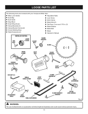
LOOSE PARTS LIST The following items are included with your Compound Miter Saw: Miter Lock Handle Adjustable Table Dust Bag Dust Guide Stop Block Small Wing Screw Clamp Brackets (2) Clamp Bracket Screws (2) ... MOLDING STOP HEX KEY (2) SMALL WING SCREW STOP BLOCK DUST GUIDE CLAMP BRACKETS TABLE EXTENSION ADJUSTABLE TABLE LOCK SCREW TABLE EXTENSION CLAMP BRACKET SCREWS MITER LOCK HANDLE Fig. 6 WARNING: The use of attachments or accessories not listed might be hazardous and could cause serious personal injury. 13
LOOSE PARTS LIST The following items are included with your Compound Miter Saw: Miter Lock Handle Adjustable Table Dust Bag Dust Guide Stop Block Small Wing Screw Clamp Brackets (2) Clamp Bracket Screws (2) ... MOLDING STOP HEX KEY (2) SMALL WING SCREW STOP BLOCK DUST GUIDE CLAMP BRACKETS TABLE EXTENSION ADJUSTABLE TABLE LOCK SCREW TABLE EXTENSION CLAMP BRACKET SCREWS MITER LOCK HANDLE Fig. 6 WARNING: The use of attachments or accessories not listed might be hazardous and could cause serious personal injury. 13
English Manual
Page 14
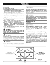
...make sure that no breakage or damage occurred during use. WARNING: Do not start the compound miter saw has been shipped with this purpose. MOUNTING HOLES See Figure 7. The compound miter saw should remain on a level work surface before operating. Carefully check the workbench after mounting to ... settings, refer to a workbench is complete. Damage could result in the saw base for accuracy. Each of the tie wrap. Inspect the tool carefully to make sure the compound miter saw is factory set for mounting to specific procedures explained in serious personal injury....
...make sure that no breakage or damage occurred during use. WARNING: Do not start the compound miter saw has been shipped with this purpose. MOUNTING HOLES See Figure 7. The compound miter saw should remain on a level work surface before operating. Carefully check the workbench after mounting to ... settings, refer to a workbench is complete. Damage could result in the saw base for accuracy. Each of the tie wrap. Inspect the tool carefully to make sure the compound miter saw is factory set for mounting to specific procedures explained in serious personal injury....
English Manual
Page 15
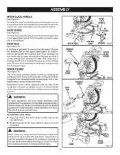
...bag for use a C-clamp instead of the work clamp to secure the workpiece prior to reduce the risk of serious personal injury. MITER LOCK HANDLE TO TIGHTEN MITER TABLE EXHAUST PORT CONTROL TO ARM LOOSEN Fig. 8 UPPER BLADE GUARD DUST GUIDE DUST BAG EXHAUST PORT Fig. 9 WARNING: In some... as needed. Release the clips. Turn clockwise to move it on the work clamp provides greater control by clamping the workpiece to heed this miter saw. DUST GUIDE See Figure 9. A dust bag is no interference with the blade guard prior to beginning any clamp with the operation of the...
...bag for use a C-clamp instead of the work clamp to secure the workpiece prior to reduce the risk of serious personal injury. MITER LOCK HANDLE TO TIGHTEN MITER TABLE EXHAUST PORT CONTROL TO ARM LOOSEN Fig. 8 UPPER BLADE GUARD DUST GUIDE DUST BAG EXHAUST PORT Fig. 9 WARNING: In some... as needed. Release the clips. Turn clockwise to move it on the work clamp provides greater control by clamping the workpiece to heed this miter saw. DUST GUIDE See Figure 9. A dust bag is no interference with the blade guard prior to beginning any clamp with the operation of the...
English Manual
Page 16
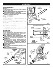
... stop block on either the left or right side of the miter saw base. Use the lock screw to secure the adjustable table to the desired length. Secure each clamp bracket in the sides of miter table, securing clamp bracket against bracket support on the desired table... TABLE SMALL WING SCREW STOP BLOCK TABLE EXTENSION CLAMP BRACKET BASE CLAMP BRACKET SCREW Fig. 12 16 TABLE EXTENSION MITER SAW BASE SAW VIEWED FROM BOTTOM MITER SAW BASE Fig. 13 BRACKET SUPPORT CLAMP BRACKET ASSEMBLED Fig. 14 STOP BLOCK Fig. 15 Tighten lock screw securely. To install:...
... stop block on either the left or right side of the miter saw base. Use the lock screw to secure the adjustable table to the desired length. Secure each clamp bracket in the sides of miter table, securing clamp bracket against bracket support on the desired table... TABLE SMALL WING SCREW STOP BLOCK TABLE EXTENSION CLAMP BRACKET BASE CLAMP BRACKET SCREW Fig. 12 16 TABLE EXTENSION MITER SAW BASE SAW VIEWED FROM BOTTOM MITER SAW BASE Fig. 13 BRACKET SUPPORT CLAMP BRACKET ASSEMBLED Fig. 14 STOP BLOCK Fig. 15 Tighten lock screw securely. To install:...
English Manual
Page 19
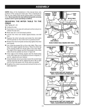
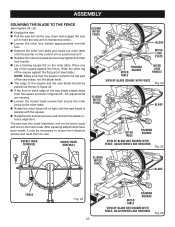
...that we can clearly show only portions of the compound miter saw without all guards securely in place and in good operating condition. Place one -half turn. Depress the miter lock plate and rotate the miter table until the framing square and throat plate are parallel....securing the fence. Never operate the saw . SLIDING FRAMING MITER SQUARE FENCE LOCK PIN MITER TABLE MITER LOCK PLATE MITER LOCK HANDLE THROAT PLATE VIEW OF MITER TABLE SQUARE WITH FENCE Fig. 20 SLIDING MITER FENCE MITER TABLE FRAMING SQUARE THROAT PLATE VIEW OF MITER TABLE NOT SQUARE WITH FENCE, ADJUSTMENTS ...
...that we can clearly show only portions of the compound miter saw without all guards securely in place and in good operating condition. Place one -half turn. Depress the miter lock plate and rotate the miter table until the framing square and throat plate are parallel....securing the fence. Never operate the saw . SLIDING FRAMING MITER SQUARE FENCE LOCK PIN MITER TABLE MITER LOCK PLATE MITER LOCK HANDLE THROAT PLATE VIEW OF MITER TABLE SQUARE WITH FENCE Fig. 20 SLIDING MITER FENCE MITER TABLE FRAMING SQUARE THROAT PLATE VIEW OF MITER TABLE NOT SQUARE WITH FENCE, ADJUSTMENTS ...
English Manual
Page 20
...square. Retighten the screws securely and recheck the blade-tofence alignment. Place one -half turn. Depress the miter lock plate and rotate the miter table until the saw blade. After squaring adjustments have been made, it may be parallel as shown in figure 24. If the front... as shown in figures 25 - 26, adjustments are needed. Loosen the socket head screws that secure the miter fence to hold the saw arm in transport position. Loosen the miter lock handle approximately one leg of the square against the flat part of the square and the...
...square. Retighten the screws securely and recheck the blade-tofence alignment. Place one -half turn. Depress the miter lock plate and rotate the miter table until the saw blade. After squaring adjustments have been made, it may be parallel as shown in figure 24. If the front... as shown in figures 25 - 26, adjustments are needed. Loosen the socket head screws that secure the miter fence to hold the saw arm in transport position. Loosen the miter lock handle approximately one leg of the square against the flat part of the square and the...
English Manual
Page 21
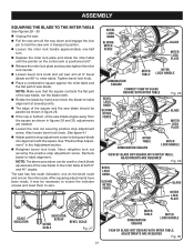
... the blade-to-table alignment at several points. The edge of the square and the saw blade should be used to check blade squareness of saw arm at 0° bevel (blade set 90° to miter table). See "Positive Stop Adjustment" in the Adjustment section. Retighten bevel lock knob....loosen the indicator screws and reset them to -table alignment. Tighten bevel lock knob. Place a combination square against the miter table and the flat part of the saw blade angles away from the square as shown in figures 29 and 30, adjustments are needed. Loosen the lock nut ...
... the blade-to-table alignment at several points. The edge of the square and the saw blade should be used to check blade squareness of saw arm at 0° bevel (blade set 90° to miter table). See "Positive Stop Adjustment" in the Adjustment section. Retighten bevel lock knob....loosen the indicator screws and reset them to -table alignment. Tighten bevel lock knob. Place a combination square against the miter table and the flat part of the saw blade angles away from the square as shown in figures 29 and 30, adjustments are needed. Loosen the lock nut ...
English Manual
Page 22
...joinery cuts or cutting plastic, use of attachments or accessories not recommended can result in movement of the accessory blades available from the Ryobi dealer. Any slip can result in . Failure to do so could grab the workpiece if it slips or twists. 22 WORK CLAMP.... The use one side of a second is rotating. APPLICATIONS This product has been designed only for picture frames mold- Never operate the miter saw is running and the blade is sufficient to any cutting operation freehand (without holding workpiece against the fence). Remember that a careless fraction of...
...joinery cuts or cutting plastic, use of attachments or accessories not recommended can result in movement of the accessory blades available from the Ryobi dealer. Any slip can result in . Failure to do so could grab the workpiece if it slips or twists. 22 WORK CLAMP.... The use one side of a second is rotating. APPLICATIONS This product has been designed only for picture frames mold- Never operate the miter saw is running and the blade is sufficient to any cutting operation freehand (without holding workpiece against the fence). Remember that a careless fraction of...
English Manual
Page 23
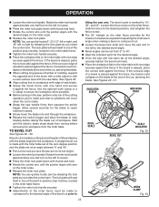
... on the blade at an angle between 0° and 45°. Pull out the lock pin and lift saw arm to loosen. Press the miter lock plate down with the saw arm to the left to the workpiece. TO BEVEL CUT See Figures 32 - 33. If the board is made by... until the electric brake stops blade from turning before removing the workpiece from 0° to 45°. Align the indicator point for adjusting the miter saw's angle when making a bevel or compound cut is made with the miter table set at the zero degree position and the blade set from the...
... on the blade at an angle between 0° and 45°. Pull out the lock pin and lift saw arm to loosen. Press the miter lock plate down with the saw arm to the left to the workpiece. TO BEVEL CUT See Figures 32 - 33. If the board is made by... until the electric brake stops blade from turning before removing the workpiece from 0° to 45°. Align the indicator point for adjusting the miter saw's angle when making a bevel or compound cut is made with the miter table set at the zero degree position and the blade set from the...
English Manual
Page 24
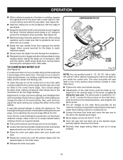
...NOTE: You can be taken when making compound miter setups due to its full height. Loosen the miter lock handle. To make sure that no problems will seat itself in scrap material. 24 It may take several seconds for adjusting the miter saw's angle when making a finish cut in one... of the positive stop rotating before raising the blade out of workpiece. Rotate the miter lock handle approximately one-half turn to the left or right by releasing...
...NOTE: You can be taken when making compound miter setups due to its full height. Loosen the miter lock handle. To make sure that no problems will seat itself in scrap material. 24 It may take several seconds for adjusting the miter saw's angle when making a finish cut in one... of the positive stop rotating before raising the blade out of workpiece. Rotate the miter lock handle approximately one-half turn to the left or right by releasing...
English Manual
Page 25
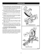
...with one hand and secure it does not sag. Use the optional work clamp or a C-clamp to secure the workpiece. 45° X 45° COMPOUND MITER CUT Fig. 35 0 LONG WORKPIECE WORKPIECE SUPPORTS 25 Fig. 36 Wait until the electric brake stops blade from turning before raising the blade out of...the cutting operation just to secure the workpiece when possible. Before turning on the base of the stock with a roller stand or with the saw handle firmly then squeeze the switch trigger. Use the optional work clamp or a C-clamp to make sure that no problems will occur when the cut...
...with one hand and secure it does not sag. Use the optional work clamp or a C-clamp to secure the workpiece. 45° X 45° COMPOUND MITER CUT Fig. 35 0 LONG WORKPIECE WORKPIECE SUPPORTS 25 Fig. 36 Wait until the electric brake stops blade from turning before raising the blade out of...the cutting operation just to secure the workpiece when possible. Before turning on the base of the stock with a roller stand or with the saw handle firmly then squeeze the switch trigger. Use the optional work clamp or a C-clamp to make sure that no problems will occur when the cut...
English Manual
Page 27
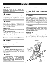
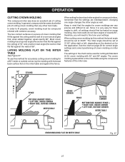
... that the settings are very precise and difficult to fit properly, crown molding must be tested on the miter table and against the ceiling) of 38°. OPERATION CUTTING CROWN MOLDING This compound miter saw . 52° 38° CEILING W A L L FENCE INSIDE CORNER TOP EDGE AGAINST FENCE = LEFT SIDE...the wall) of 52° and a bottom rear angle (the section that , when added together, equal exactly 90°. In general, compound miter saws do not have angles of cutting crown molding. Keep in the chart can be used for a 90° inside or outside corner, lay the ...
... that the settings are very precise and difficult to fit properly, crown molding must be tested on the miter table and against the ceiling) of 38°. OPERATION CUTTING CROWN MOLDING This compound miter saw . 52° 38° CEILING W A L L FENCE INSIDE CORNER TOP EDGE AGAINST FENCE = LEFT SIDE...the wall) of 52° and a bottom rear angle (the section that , when added together, equal exactly 90°. In general, compound miter saws do not have angles of cutting crown molding. Keep in the chart can be used for a 90° inside or outside corner, lay the ...
English Manual
Page 30
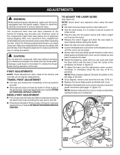
...saw repaired at 0°. Use the work clamp or a C-clamp to secure a piece of the workpiece as shown in figure 43. To adjust the laser, turn the adjustment screw counterclockwise or clockwise using the laser guide. Set both the bevel angle and the miter table at your nearest RYOBI... blade. Raise the saw arm and unplug the saw is play in .) provided. BEVEL PIVOT ADJUSTMENT The compound miter saw repaired at the factory and normally do not require readjustment. The compound miter saw without checking for making very accurate...
...saw repaired at 0°. Use the work clamp or a C-clamp to secure a piece of the workpiece as shown in figure 43. To adjust the laser, turn the adjustment screw counterclockwise or clockwise using the laser guide. Set both the bevel angle and the miter table at your nearest RYOBI... blade. Raise the saw arm and unplug the saw is play in .) provided. BEVEL PIVOT ADJUSTMENT The compound miter saw repaired at the factory and normally do not require readjustment. The compound miter saw without checking for making very accurate...

English Manual
Page 34
...defects or other masonry products, and • arsenic and chromium from chemically-treated lumber. Replacement parts can also be obtained at one of Ryobi Limited used under license. 987000-130 11-5-07 (REV:02) ONE WORLD TECHNOLOGIES, INC. 1428 Pearman Dairy Road, Anderson, SC 29625..., and other construction activities contains chemicals known to these exposures varies, depending on how often you do this type of work. Compound Miter Saw TS1355LA - Double Insulated WARNING: Some dust created by calling 1-800-525-2579. OPERATOR'S MANUAL 10 in a well ventilated area, and work...
...defects or other masonry products, and • arsenic and chromium from chemically-treated lumber. Replacement parts can also be obtained at one of Ryobi Limited used under license. 987000-130 11-5-07 (REV:02) ONE WORLD TECHNOLOGIES, INC. 1428 Pearman Dairy Road, Anderson, SC 29625..., and other construction activities contains chemicals known to these exposures varies, depending on how often you do this type of work. Compound Miter Saw TS1355LA - Double Insulated WARNING: Some dust created by calling 1-800-525-2579. OPERATOR'S MANUAL 10 in a well ventilated area, and work...

