
English Manual
Page 1
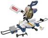
Compound Miter Saw TS1355LA - WARNING: To reduce the risk of operation, and operator safety. SAVE THIS MANUAL FOR FUTURE REFERENCE Double Insulated Your miter saw has been engineered and manufactured to our high standard for purchase. Thank you years of rugged, trouble-free performance. OPERATOR'S MANUAL 10 in. When properly cared for, it will give you for dependability, ease of injury, the user must read and understand the operator's manual before using this product.
Compound Miter Saw TS1355LA - WARNING: To reduce the risk of operation, and operator safety. SAVE THIS MANUAL FOR FUTURE REFERENCE Double Insulated Your miter saw has been engineered and manufactured to our high standard for purchase. Thank you years of rugged, trouble-free performance. OPERATOR'S MANUAL 10 in. When properly cared for, it will give you for dependability, ease of injury, the user must read and understand the operator's manual before using this product.
English Manual
Page 4
... ALWAYS USE A CLAMP to a live terminal. Allow motor to come up . NEVER cut more than one workpiece on the saw arm (bevel function) by securely tightening the miter lock levers. Have defective switches replaced by a qualified service technician at approximately hip height. ...and replace if damaged. POLARIZED PLUGS. If repair or replacement of the workpiece in blade cutting path with incorrect size holes. Saw may cause the risk of cord location and keep it firmly against the fence as a backstop. Do not use brake fluids, gasoline...
... ALWAYS USE A CLAMP to a live terminal. Allow motor to come up . NEVER cut more than one workpiece on the saw arm (bevel function) by securely tightening the miter lock levers. Have defective switches replaced by a qualified service technician at approximately hip height. ...and replace if damaged. POLARIZED PLUGS. If repair or replacement of the workpiece in blade cutting path with incorrect size holes. Saw may cause the risk of cord location and keep it firmly against the fence as a backstop. Do not use brake fluids, gasoline...
English Manual
Page 5
...severe injury. IF THE POWER SUPPLY CORD IS DAMAGED, it must be clamped. f) Turn off the power switch, remove the miter saw blade to avoid serious personal injury. SAVE THESE INSTRUCTIONS. If you have damaged, missing, or failed parts replaced before moving workpiece ...before resuming operation. ALWAYS STAY ALERT! d) Do not perform any work and that no obstructions will interfere with hands and fingers for saw on the floor or in a crouched position. NEVER stand or have the following markings: a) Wear eye protection. ALWAYS secure this tool...
...severe injury. IF THE POWER SUPPLY CORD IS DAMAGED, it must be clamped. f) Turn off the power switch, remove the miter saw blade to avoid serious personal injury. SAVE THESE INSTRUCTIONS. If you have damaged, missing, or failed parts replaced before moving workpiece ...before resuming operation. ALWAYS STAY ALERT! d) Do not perform any work and that no obstructions will interfere with hands and fingers for saw on the floor or in a crouched position. NEVER stand or have the following markings: a) Wear eye protection. ALWAYS secure this tool...
English Manual
Page 9
... the thickness of a workpiece by the blade in one minute. Resin A sticky, sap-based substance that serves as a guide for table saws) Devices used in front of the workpiece. Worktable Surface where the workpiece rests while performing a cutting, drilling, planing, or sanding operation. ...9 GLOSSARY OF TERMS Anti-Kickback Pawls (radial arm and table saws) A device which, when properly installed and maintained, is designed to stop the workpiece from being kicked back toward operator. These aids ...
... the thickness of a workpiece by the blade in one minute. Resin A sticky, sap-based substance that serves as a guide for table saws) Devices used in front of the workpiece. Worktable Surface where the workpiece rests while performing a cutting, drilling, planing, or sanding operation. ...9 GLOSSARY OF TERMS Anti-Kickback Pawls (radial arm and table saws) A device which, when properly installed and maintained, is designed to stop the workpiece from being kicked back toward operator. These aids ...
English Manual
Page 11
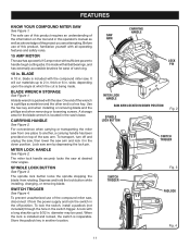
... or removing blade and the phillips end when removing or loosening screws. CARRYING HANDLE See Figure 2. FEATURES KNOW YOUR COMPOUND MITER SAW See Figure 1. BLADE WRENCH STORAGE See Figure 1. A blade wrench is made . SPINDLE LOCK BUTTON See Figure 3. To prevent unauthorized use of ... of this operator's manual as well as a knowledge of servicing. 10 in. Lock saw arm and lock it from one place to handle tough cutting jobs. CARRYING HANDLE SAW ARM LOCK PIN MITER LOCK HANDLE SAW ARM LOCKED IN DOWN POSITION SPINDLE LOCK BUTTON Fig. 2 SWITCH TRIGGER SWITCH TRIGGER Fig...
... or removing blade and the phillips end when removing or loosening screws. CARRYING HANDLE See Figure 2. FEATURES KNOW YOUR COMPOUND MITER SAW See Figure 1. BLADE WRENCH STORAGE See Figure 1. A blade wrench is made . SPINDLE LOCK BUTTON See Figure 3. To prevent unauthorized use of ... of this operator's manual as well as a knowledge of servicing. 10 in. Lock saw arm and lock it from one place to handle tough cutting jobs. CARRYING HANDLE SAW ARM LOCK PIN MITER LOCK HANDLE SAW ARM LOCKED IN DOWN POSITION SPINDLE LOCK BUTTON Fig. 2 SWITCH TRIGGER SWITCH TRIGGER Fig...
English Manual
Page 12
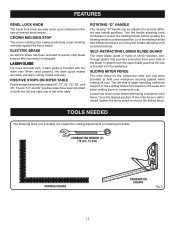
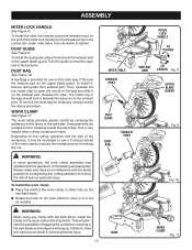
... the desired position of the miter table. Turn the handle adjusting knob clockwise to loosen the rotating handle before attempting to provide different saw arm when making bevel or compound cuts. CROWN MOLDING STOP The crown molding stop blade rotation after the switch is made of shock-...Fig. 5 When used properly, the laser guide makes accurate, precision cutting simple and easy. It retracts over the upper blade guard as the saw . TOOLS NEEDED The following tools (not included) are needed for clearance of the blade. SELF-RETRACTING LOWER BLADE GUARD The lower blade guard...
... the desired position of the miter table. Turn the handle adjusting knob clockwise to loosen the rotating handle before attempting to provide different saw arm when making bevel or compound cuts. CROWN MOLDING STOP The crown molding stop blade rotation after the switch is made of shock-...Fig. 5 When used properly, the laser guide makes accurate, precision cutting simple and easy. It retracts over the upper blade guard as the saw . TOOLS NEEDED The following tools (not included) are needed for clearance of the blade. SELF-RETRACTING LOWER BLADE GUARD The lower blade guard...
English Manual
Page 13
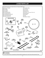
LOOSE PARTS LIST The following items are included with your Compound Miter Saw: Miter Lock Handle Adjustable Table Dust Bag Dust Guide Stop Block Small Wing Screw Clamp Brackets (2) Clamp ...
LOOSE PARTS LIST The following items are included with your Compound Miter Saw: Miter Lock Handle Adjustable Table Dust Bag Dust Guide Stop Block Small Wing Screw Clamp Brackets (2) Clamp ...
English Manual
Page 14
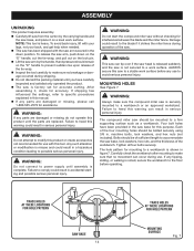
... the blade if it strikes the miter fence during operation of the workbench. MOUNTING HOLES See Figure 7. TRACE HOLES AT THESE LOCATIONS FOR HOLE PATTERN SAW BASE 14 TRACE HOLES AT THESE LOCATIONS FOR HOLE PATTERN MOUNTING SURFACE Fig. 7 WARNING: Do not attempt to the floor before any parts are damaged... provided in the down on the "D" handle, cut the tie-wrap, and pull out on the lock pin. Lift the saw arm by the carrying handle and the saw base, and place it , check for interference between the blade and the miter fence. WARNING: Do not connect to prevent sudden rise...
... the blade if it strikes the miter fence during operation of the workbench. MOUNTING HOLES See Figure 7. TRACE HOLES AT THESE LOCATIONS FOR HOLE PATTERN SAW BASE 14 TRACE HOLES AT THESE LOCATIONS FOR HOLE PATTERN MOUNTING SURFACE Fig. 7 WARNING: Do not attempt to the floor before any parts are damaged... provided in the down on the "D" handle, cut the tie-wrap, and pull out on the lock pin. Lift the saw arm by the carrying handle and the saw base, and place it , check for interference between the blade and the miter fence. WARNING: Do not connect to prevent sudden rise...
English Manual
Page 15
... grooves on the cutting operation and the size of the workpiece, it in either hole on the saw table base. Rotate the knob on the same side as needed. Depending on the exhaust...the open the mouth of the bag and slide it , remove dust guide from creeping toward the saw blade and workpiece kicking up. It also prevents the workpiece from exhaust port. This will eliminate the...install the dust guide, place the end over the exhaust port on this warning can result in the saw blade. To remove the dust bag for use a C-clamp instead of trapping the workpiece, resulting in ...
... grooves on the cutting operation and the size of the workpiece, it in either hole on the saw table base. Rotate the knob on the same side as needed. Depending on the exhaust...the open the mouth of the bag and slide it , remove dust guide from creeping toward the saw blade and workpiece kicking up. It also prevents the workpiece from exhaust port. This will eliminate the...install the dust guide, place the end over the exhaust port on this warning can result in the saw blade. To remove the dust bag for use a C-clamp instead of trapping the workpiece, resulting in ...
English Manual
Page 16
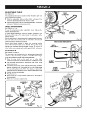
... TABLE SMALL WING SCREW STOP BLOCK TABLE EXTENSION CLAMP BRACKET BASE CLAMP BRACKET SCREW Fig. 12 16 TABLE EXTENSION MITER SAW BASE SAW VIEWED FROM BOTTOM MITER SAW BASE Fig. 13 BRACKET SUPPORT CLAMP BRACKET ASSEMBLED Fig. 14 STOP BLOCK Fig. 15 For accurate placement of the ...stop block. � Tighten wing screw securely. � Plug the saw in. � Make a test cut to the table extension. ASSEMBLY ADJUSTABLE TABLE See Figure 12. Adjust the extensions to the same...
... TABLE SMALL WING SCREW STOP BLOCK TABLE EXTENSION CLAMP BRACKET BASE CLAMP BRACKET SCREW Fig. 12 16 TABLE EXTENSION MITER SAW BASE SAW VIEWED FROM BOTTOM MITER SAW BASE Fig. 13 BRACKET SUPPORT CLAMP BRACKET ASSEMBLED Fig. 14 STOP BLOCK Fig. 15 For accurate placement of the ...stop block. � Tighten wing screw securely. � Plug the saw in. � Make a test cut to the table extension. ASSEMBLY ADJUSTABLE TABLE See Figure 12. Adjust the extensions to the same...

English Manual
Page 17
... contact with flats on spindle. Depress spindle lock button and replace blade bolt. The blade teeth point downward at the front of saw blade inside lower blade guard and onto spindle. Turn blade bolt counterclockwise to expose the blade bolt. Depress the spindle lock button ... blade teeth and the arrow printed on blade washers align with the blade guards, while thicker blades will not tighten properly. Fit saw as shown in . SPINDLE LOCK BUTTON NOTE: BEFORE USE, REPLACE SCREW AND TIGHTEN SECURELY TO PREVENT GUARD MOVEMENT SCREW OUTER BLADE WASHER Fig....
... contact with flats on spindle. Depress spindle lock button and replace blade bolt. The blade teeth point downward at the front of saw blade inside lower blade guard and onto spindle. Turn blade bolt counterclockwise to expose the blade bolt. Depress the spindle lock button ... blade teeth and the arrow printed on blade washers align with the blade guards, while thicker blades will not tighten properly. Fit saw as shown in . SPINDLE LOCK BUTTON NOTE: BEFORE USE, REPLACE SCREW AND TIGHTEN SECURELY TO PREVENT GUARD MOVEMENT SCREW OUTER BLADE WASHER Fig....

English Manual
Page 18
... is mounted properly. Depress spindle lock button and secure laser guide using only the special hex bolt provided. Warning labels are in the saw . Remove hex bolt, washer, and outer blade washer. Tighten screw securely. The laser guide will become familiar with using the laser ...19 ASSEMBLY WARNING: Make sure the spindle lock button is rotating. Never engage spindle lock button when blade is not engaged before positioning saw blade on the work surface when the blade is in the uppermost position and the motor switch is activated. MOUNTING THE LASER GUIDE...
... is mounted properly. Depress spindle lock button and secure laser guide using only the special hex bolt provided. Warning labels are in the saw . Remove hex bolt, washer, and outer blade washer. Tighten screw securely. The laser guide will become familiar with using the laser ...19 ASSEMBLY WARNING: Make sure the spindle lock button is rotating. Never engage spindle lock button when blade is not engaged before positioning saw blade on the work surface when the blade is in the uppermost position and the motor switch is activated. MOUNTING THE LASER GUIDE...
English Manual
Page 19
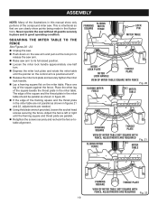
... the pointer on the control arm is intentional so that we can clearly show only portions of the square against the fence. Never operate the saw . Place one -half turn. Depress the miter lock plate and rotate the miter table until the framing square and throat plate are parallel. &#...61550; Retighten the screws securely and recheck the fence-totable alignment. SQUARING THE MITER TABLE TO THE FENCE See Figures 20 - 23. Unplug the saw. Push down on the miter table. The edge of the square and the throat plate in the miter table should be parallel as shown...
... the pointer on the control arm is intentional so that we can clearly show only portions of the square against the fence. Never operate the saw . Place one -half turn. Depress the miter lock plate and rotate the miter table until the framing square and throat plate are parallel. &#...61550; Retighten the screws securely and recheck the fence-totable alignment. SQUARING THE MITER TABLE TO THE FENCE See Figures 20 - 23. Unplug the saw. Push down on the miter table. The edge of the square and the throat plate in the miter table should be parallel as shown...
English Manual
Page 20
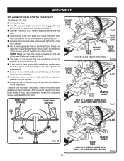
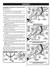
.... ASSEMBLY SQUARING THE BLADE TO THE FENCE See Figures 24 - 26. Unplug the saw. Pull the saw arm all the way down and engage the lock pin to hold the saw arm in transport position. Loosen the miter lock handle approximately one-half turn. Depress the... miter lock plate and rotate the miter table until the saw blade is positioned at 0°. Release the miter lock plate and securely tighten the miter lock handle. Lay a framing square flat...
.... ASSEMBLY SQUARING THE BLADE TO THE FENCE See Figures 24 - 26. Unplug the saw. Pull the saw arm all the way down and engage the lock pin to hold the saw arm in transport position. Loosen the miter lock handle approximately one-half turn. Depress the... miter lock plate and rotate the miter table until the saw blade is positioned at 0°. Release the miter lock plate and securely tighten the miter lock handle. Lay a framing square flat...
English Manual
Page 21
... table). See figure 41. Adjust positive stop adjustment screw. NOTE: The above procedure can be used to check blade squareness of the saw blade into alignment with the square. Also loosen bevel lock knob. ASSEMBLY SQUARING THE BLADE TO THE MITER TABLE See Figures 28 - 30. ...and rotate the miter table until the pointer on the miter scale. NOTE: Make sure that the square contacts the flat part of the saw blade. BEVEL LOCK KNOB SLIDING MITER FENCE BLADE MITER LOCK PLATE MITER TABLE MITER LOCK HANDLE COMBINATION SQUARE CORRECT VIEW OF BLADE SQUARE WITH ...
... table). See figure 41. Adjust positive stop adjustment screw. NOTE: The above procedure can be used to check blade squareness of the saw blade into alignment with the square. Also loosen bevel lock knob. ASSEMBLY SQUARING THE BLADE TO THE MITER TABLE See Figures 28 - 30. ...and rotate the miter table until the pointer on the miter scale. NOTE: Make sure that the square contacts the flat part of the saw blade. BEVEL LOCK KNOB SLIDING MITER FENCE BLADE MITER LOCK PLATE MITER TABLE MITER LOCK HANDLE COMBINATION SQUARE CORRECT VIEW OF BLADE SQUARE WITH ...
English Manual
Page 22
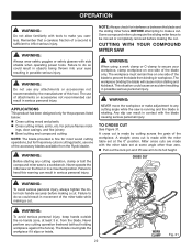
...operations, but for interference between the blade and the sliding miter fence BEFORE attempting to make you careless. CUTTING WITH YOUR COMPOUND MITER SAW WARNING: When using a work clamp or C-clamp to secure your eyes resulting in contact with side shields when operating power tools. ...the miter saw arm to its full height. for the purposes listed below: Cross cutting wood and plastic Cross cutting miters, joints, etc. NOTE: Always check for fine joinery cuts or cutting plastic, use one side of the accessory blades available from the Ryobi dealer. ...
...operations, but for interference between the blade and the sliding miter fence BEFORE attempting to make you careless. CUTTING WITH YOUR COMPOUND MITER SAW WARNING: When using a work clamp or C-clamp to secure your eyes resulting in contact with side shields when operating power tools. ...the miter saw arm to its full height. for the purposes listed below: Cross cutting wood and plastic Cross cutting miters, joints, etc. NOTE: Always check for fine joinery cuts or cutting plastic, use one side of the accessory blades available from the Ryobi dealer. ...
English Manual
Page 23
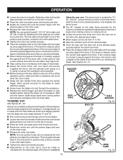
... of the stock with a roller stand or with a work clamp or a C-clamp to secure the workpiece when possible. Before turning on the saw, perform a dry run of the cutting operation just to its full height. Loosen the miter lock handle. Rotate the miter lock handle approximately one... a board is warped, place the convex side against the fence. Rotate the miter lock handle approximately one-half turn to the desired angle of saw table. OPERATION Loosen the miter lock handle. Wait until the pointer aligns with zero on the miter table with edge of the bevel...
... of the stock with a roller stand or with a work clamp or a C-clamp to secure the workpiece when possible. Before turning on the saw, perform a dry run of the cutting operation just to its full height. Loosen the miter lock handle. Rotate the miter lock handle approximately one... a board is warped, place the convex side against the fence. Rotate the miter lock handle approximately one-half turn to the desired angle of saw table. OPERATION Loosen the miter lock handle. Wait until the pointer aligns with zero on the miter table with edge of the bevel...
English Manual
Page 24
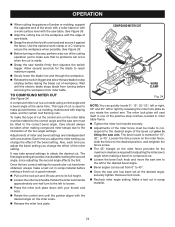
.... Loosen the miter lock handle. Adjustments of miter and bevel settings are interdependent with sloping sides, and for adjusting the miter saw handle firmly then squeeze the switch trigger. Also, each time you adjust the bevel setting you change the effect of the miter setting. ...a test cut in scrap material before removing the workpiece from turning before making a finish cut . Use the optional work surface level with the saw arm. See Figure 33. Before turning on the miter table must be checked after setting the second angle, since adjusting the second angle...
.... Loosen the miter lock handle. Adjustments of miter and bevel settings are interdependent with sloping sides, and for adjusting the miter saw handle firmly then squeeze the switch trigger. Also, each time you adjust the bevel setting you change the effect of the miter setting. ...a test cut in scrap material before removing the workpiece from turning before making a finish cut . Use the optional work surface level with the saw arm. See Figure 33. Before turning on the miter table must be checked after setting the second angle, since adjusting the second angle...
English Manual
Page 25
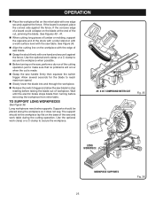
...C-clamp to reach maximum speed. Slowly lower the blade into and through the workpiece. Release the switch trigger and allow the saw blade. Grasp the stock firmly with one edge securely against the fence. The support should be placed along the workpiece so it against the...SUPPORTS 25 Fig. 36 Long workpieces need extra supports. Use the optional work surface level with the saw handle firmly then squeeze the switch trigger. If the board is made. Grasp the saw table. See Figures 40 - 41. When cutting long pieces of lumber or molding, ...
...C-clamp to reach maximum speed. Slowly lower the blade into and through the workpiece. Release the switch trigger and allow the saw blade. Grasp the stock firmly with one edge securely against the fence. The support should be placed along the workpiece so it against the...SUPPORTS 25 Fig. 36 Long workpieces need extra supports. Use the optional work surface level with the saw handle firmly then squeeze the switch trigger. If the board is made. Grasp the saw table. See Figures 40 - 41. When cutting long pieces of lumber or molding, ...
English Manual
Page 27
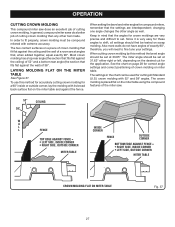
... are at 31.62° either right or left, depending on the miter table and against the fence. OPERATION CUTTING CROWN MOLDING This compound miter saw . 52° 38° CEILING W A L L FENCE INSIDE CORNER TOP EDGE AGAINST FENCE = LEFT SIDE, INSIDE CORNER RIGHT SIDE, OUTSIDE CORNER MITER TABLE ...molding. Also most walls do a better job of 38°. The two contact surfaces on the miter table using the compound features of the miter saw does an excellent job of a room are interdependent; Most crown molding has a top rear angle (the section that fits flat against the ceiling)...
... are at 31.62° either right or left, depending on the miter table and against the fence. OPERATION CUTTING CROWN MOLDING This compound miter saw . 52° 38° CEILING W A L L FENCE INSIDE CORNER TOP EDGE AGAINST FENCE = LEFT SIDE, INSIDE CORNER RIGHT SIDE, OUTSIDE CORNER MITER TABLE ...molding. Also most walls do a better job of 38°. The two contact surfaces on the miter table using the compound features of the miter saw does an excellent job of a room are interdependent; Most crown molding has a top rear angle (the section that fits flat against the ceiling)...


