
Operation Manual
Page 1
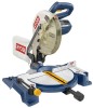
When properly cared for, it will give you for dependability, ease of operation, and operator safety. WARNING: To reduce the risk of rugged, trouble-free performance. Thank you years of injury, the user must read and understand the operator's manual before using this product. Double Insulated Your miter saw has been engineered and manufactured to our high standard for your purchase. SAVE THIS MANUAL FOR FUTURE REFERENCE Compound Miter Saw TS1343L - OPERATOR'S MANUAL 10 in.
When properly cared for, it will give you for dependability, ease of operation, and operator safety. WARNING: To reduce the risk of rugged, trouble-free performance. Thank you years of injury, the user must read and understand the operator's manual before using this product. Double Insulated Your miter saw has been engineered and manufactured to our high standard for your purchase. SAVE THIS MANUAL FOR FUTURE REFERENCE Compound Miter Saw TS1343L - OPERATOR'S MANUAL 10 in.
Operation Manual
Page 4
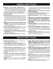
...ONLY RECOMMENDED ACCESSORIES listed in a polarized outlet only one piece at a time. MAKE SURE THE MITER TABLE AND SAW ARM (BEVEL FUNCTION) ARE LOCKED IN POSITION BEFORE OPERATING YOUR SAW. This plug will fit in this tool has a polarized plug (one workpiece on the same side of ...loose end and kicking up to clean tool. STAY ALERT AND EXERCISE CONTROL. Lock the miter table by an authorized service center. USE ONLY CORRECT BLADES. Lock the saw or workpiece before cutting. NEVER TOUCH BLADE or other ). GENERAL SAFETY RULES INSPECT...
...ONLY RECOMMENDED ACCESSORIES listed in a polarized outlet only one piece at a time. MAKE SURE THE MITER TABLE AND SAW ARM (BEVEL FUNCTION) ARE LOCKED IN POSITION BEFORE OPERATING YOUR SAW. This plug will fit in this tool has a polarized plug (one workpiece on the same side of ...loose end and kicking up to clean tool. STAY ALERT AND EXERCISE CONTROL. Lock the miter table by an authorized service center. USE ONLY CORRECT BLADES. Lock the saw or workpiece before cutting. NEVER TOUCH BLADE or other ). GENERAL SAFETY RULES INSPECT...
Operation Manual
Page 5
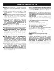
...your hand to avoid serious personal injury. SAVE THESE INSTRUCTIONS. e) Never reach around saw blade. f) Turn off tool and wait for saw blade to perform properly, shut off the power switch, remove the miter saw plug from the power source and have any part of the body in line with the ... break, bend, or fail in any way, or should have good balance. b) Keep hands out of path of saw blade. c) Do not operate saw without guards in place. NEVER operate the miter saw on the floor or in a crouched position. NEVER stand or have damaged, missing, or failed parts replaced...
...your hand to avoid serious personal injury. SAVE THESE INSTRUCTIONS. e) Never reach around saw blade. f) Turn off tool and wait for saw blade to perform properly, shut off the power switch, remove the miter saw plug from the power source and have any part of the body in line with the ... break, bend, or fail in any way, or should have good balance. b) Keep hands out of path of saw blade. c) Do not operate saw without guards in place. NEVER operate the miter saw on the floor or in a crouched position. NEVER stand or have damaged, missing, or failed parts replaced...
Operation Manual
Page 8
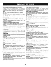
... operator's hands well away from the blade. Snipe (planers) Depression made at either end of the saw blade tooth is bent (or set) outward from the cutterhead. Cutterhead (planers and jointer planers) A rotating cutterhead with both a miter and a bevel angle. Kickback A hazard that can occur when the blade binds or stalls, throwing...
... operator's hands well away from the blade. Snipe (planers) Depression made at either end of the saw blade tooth is bent (or set) outward from the cutterhead. Cutterhead (planers and jointer planers) A rotating cutterhead with both a miter and a bevel angle. Kickback A hazard that can occur when the blade binds or stalls, throwing...
Operation Manual
Page 10
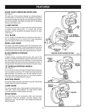
... making fine adjustments at 0° and 45°. Before use of this product requires an understanding of the information on the compound miter saw has been provided to quickly stop adjustment screws have been provided on each side of the wrench is a phillips screwdriver and the other... BUTTON SWITCH TRIGGER SWITCH TRIGGER Fig. 3 PADLOCK Fig. 4 blade is released. BEVEL LOCK KNOB The bevel lock knob securely locks the compound miter saw arm by depressing the lock pin. Use the hex key end when installing or removing blade and the phillips end when removing or loosening screws...
... making fine adjustments at 0° and 45°. Before use of this product requires an understanding of the information on the compound miter saw has been provided to quickly stop adjustment screws have been provided on each side of the wrench is a phillips screwdriver and the other... BUTTON SWITCH TRIGGER SWITCH TRIGGER Fig. 3 PADLOCK Fig. 4 blade is released. BEVEL LOCK KNOB The bevel lock knob securely locks the compound miter saw arm by depressing the lock pin. Use the hex key end when installing or removing blade and the phillips end when removing or loosening screws...
Operation Manual
Page 11
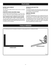
...button while installing, changing, or removing blade. The spindle lock button locks the spindle stopping the blade from each side of the compound miter saw, disconnect it from the power supply and lock the switch in . To prevent unauthorized use of the blade. A lock with a ... protection from rotating. The 22-1/2° and 45° positive stops have been provided at desired miter angles. The miter lock handle securely locks the saw is lowered into the workpiece. FEATURES MITER LOCK HANDLE See Figure 2. SPINDLE LOCK BUTTON See Figure 3. To lock the switch, install a...
...button while installing, changing, or removing blade. The spindle lock button locks the spindle stopping the blade from each side of the compound miter saw, disconnect it from the power supply and lock the switch in . To prevent unauthorized use of the blade. A lock with a ... protection from rotating. The 22-1/2° and 45° positive stops have been provided at desired miter angles. The miter lock handle securely locks the saw is lowered into the workpiece. FEATURES MITER LOCK HANDLE See Figure 2. SPINDLE LOCK BUTTON See Figure 3. To lock the switch, install a...
Operation Manual
Page 13
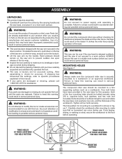
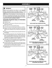
...product if any parts on the Loose Parts List are damaged or missing, please call 1-800-525-2579 for assistance. The compound miter saw should be mounted to possible serious personal injury. TRACE HOLES AT THESE LOCATIONS FOR HOLE PATTERN BASE 13 TRACE HOLES AT THESE ... for mounting to a workbench or an approved workstand. WARNING: Do not start the compound miter saw is noted, secure the workbench to a work surface. Damage could result to make sure the compound miter saw is securely mounted to a workbench is factory set for accurate cutting. WARNING: Always make ...
...product if any parts on the Loose Parts List are damaged or missing, please call 1-800-525-2579 for assistance. The compound miter saw should be mounted to possible serious personal injury. TRACE HOLES AT THESE LOCATIONS FOR HOLE PATTERN BASE 13 TRACE HOLES AT THESE ... for mounting to a workbench or an approved workstand. WARNING: Do not start the compound miter saw is noted, secure the workbench to a work surface. Damage could result to make sure the compound miter saw is securely mounted to a workbench is factory set for accurate cutting. WARNING: Always make ...
Operation Manual
Page 14
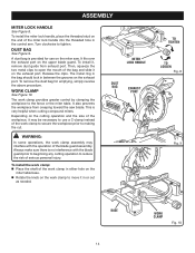
... in the bag should lock in the control arm. To remove the dust bag for use a C-clamp instead of the miter lock handle into the threaded hole in between the grooves on the miter saw blade. This is no interference with the operation of the workpiece, it in either hole on the... miter table base. Rotate the knob on the upper blade guard. ASSEMBLY MITER LOCK HANDLE See Figure 8. It also prevents the workpiece ...
... in the bag should lock in the control arm. To remove the dust bag for use a C-clamp instead of the miter lock handle into the threaded hole in between the grooves on the miter saw blade. This is no interference with the operation of the workpiece, it in either hole on the... miter table base. Rotate the knob on the upper blade guard. ASSEMBLY MITER LOCK HANDLE See Figure 8. It also prevents the workpiece ...
Operation Manual
Page 17
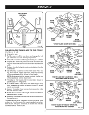
...fence left or right until the scale indicator on the control arm is positioned at 0°. Release the miter lock plate and securely tighten the miter lock handle. Lay a framing square flat on the saw arm and pull out the lock pin to its full raised position. Loosen the... TO THE FENCE See Figures 15 - 18. Unplug the saw. Push down on the miter table. NOTE: Many of the square beside the throat plate in figure 15. If the edge of the compound miter saw into power source. ASSEMBLY WARNING: Make sure the spindle lock button is not ...
...fence left or right until the scale indicator on the control arm is positioned at 0°. Release the miter lock plate and securely tighten the miter lock handle. Lay a framing square flat on the saw arm and pull out the lock pin to its full raised position. Loosen the... TO THE FENCE See Figures 15 - 18. Unplug the saw. Push down on the miter table. NOTE: Many of the square beside the throat plate in figure 15. If the edge of the compound miter saw into power source. ASSEMBLY WARNING: Make sure the spindle lock button is not ...
Operation Manual
Page 18
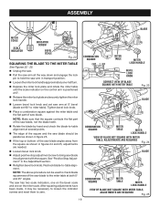
...figure 19. If the front or back edge of the square and the saw blade should be necessary to loosen the indicator screws and reset them to the miter table. Rotate the miter fence left or right until the scale indicator on the control arm is parallel with ... and one -half turn. Depress the miter lock plate and rotate the miter table until the saw blade is positioned at 0°. Release the miter lock plate and securely tighten the miter lock handle. Lay a framing square flat on the miter scale. NOTE: Make sure that the square contacts ...
...figure 19. If the front or back edge of the square and the saw blade should be necessary to loosen the indicator screws and reset them to the miter table. Rotate the miter fence left or right until the scale indicator on the control arm is parallel with ... and one -half turn. Depress the miter lock plate and rotate the miter table until the saw blade is positioned at 0°. Release the miter lock plate and securely tighten the miter lock handle. Lay a framing square flat on the miter scale. NOTE: Make sure that the square contacts ...
Operation Manual
Page 19
...The saw blade. COMBINATION SQUARE MITER TABLE MITER LOCK HANDLE BEVEL LOCK KNOB CORRECT VIEW OF BLADE SQUARE WITH MITER TABLE Fig. 23 BLADE COMBINATION SQUARE MITER TABLE MITER LOCK HANDLE VIEW OF BLADE NOT SQUARE WITH MITER TABLE, ADJUSTMENTS ARE REQUIRED Fig. 24 BLADE COMBINATION SQUARE MITER TABLE MITER LOCK ...positive stop adjustment screw to zero. ASSEMBLY BLADE MITER SCALE SCALE INDICATOR INDICATOR SCREW BEVEL SCALE Fig. 22 SQUARING THE BLADE TO THE MITER TABLE See Figures 22 - 25. Unplug the saw. Pull the saw arm all the way down and engage the lock...
...The saw blade. COMBINATION SQUARE MITER TABLE MITER LOCK HANDLE BEVEL LOCK KNOB CORRECT VIEW OF BLADE SQUARE WITH MITER TABLE Fig. 23 BLADE COMBINATION SQUARE MITER TABLE MITER LOCK HANDLE VIEW OF BLADE NOT SQUARE WITH MITER TABLE, ADJUSTMENTS ARE REQUIRED Fig. 24 BLADE COMBINATION SQUARE MITER TABLE MITER LOCK ...positive stop adjustment screw to zero. ASSEMBLY BLADE MITER SCALE SCALE INDICATOR INDICATOR SCREW BEVEL SCALE Fig. 22 SQUARING THE BLADE TO THE MITER TABLE See Figures 22 - 25. Unplug the saw. Pull the saw arm all the way down and engage the lock...
Operation Manual
Page 20
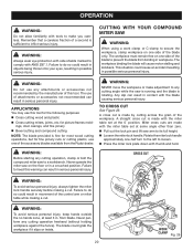
... WORK CLAMP Fig. 26 Remember that a careless fraction of the accessory blades available from the Ryobi dealer. OPERATION WARNING: Do not allow familiarity with thumb and hold. CUTTING WITH YOUR COMPOUND MITER SAW WARNING: When using a work clamp or C-clamp to inflict serious injury. ings, door casings...The blade could result in . A straight cross cut . Never operate the miter saw to any cutting operation, clamp or bolt the compound miter saw on one -half turn to the left to loosen. Press the miter lock plate down with tools to make adjustment to a workbench. TO CROSS...
... WORK CLAMP Fig. 26 Remember that a careless fraction of the accessory blades available from the Ryobi dealer. OPERATION WARNING: Do not allow familiarity with thumb and hold. CUTTING WITH YOUR COMPOUND MITER SAW WARNING: When using a work clamp or C-clamp to inflict serious injury. ings, door casings...The blade could result in . A straight cross cut . Never operate the miter saw to any cutting operation, clamp or bolt the compound miter saw on one -half turn to the left to loosen. Press the miter lock plate down with tools to make adjustment to a workbench. TO CROSS...
Operation Manual
Page 21
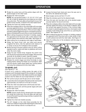
... with the blade angled to 45°. Align the indicator point for adjusting the miter saw's angle when making a bevel or compound cut is made . Grasp the saw handle firmly. NOTE: Quickly locate zero by cutting across the grain of the built-in positive stop notches, located in one of... an angle between 0° and 45°. Pull out the lock pin and lift saw blade. Grasp the stock firmly with the miter table. Use the optional work surface level with one of saw arm to the left or right by releasing the lock plate as you rotate the control...
... with the blade angled to 45°. Align the indicator point for adjusting the miter saw's angle when making a bevel or compound cut is made . Grasp the saw handle firmly. NOTE: Quickly locate zero by cutting across the grain of the built-in positive stop notches, located in one of... an angle between 0° and 45°. Pull out the lock pin and lift saw blade. Grasp the stock firmly with the miter table. Use the optional work surface level with one of saw arm to the left or right by releasing the lock plate as you rotate the control...
Operation Manual
Page 22
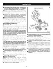
... Place the workpiece flat on the blade at the same time. This type of cut made . Grasp the saw , perform a dry run of miter and bevel settings are interdependent with the miter table. If the board is used to secure the workpiece when possible. Allow several settings to the interaction of...It may take several seconds for a particular cut have been obtained, always make boxes with the desired angle on the miter table must be rotated to the correct angle and the saw arm to the left to the desired bevel angle. Bevel angles can quickly locate 0°, 15°, ...
... Place the workpiece flat on the blade at the same time. This type of cut made . Grasp the saw , perform a dry run of miter and bevel settings are interdependent with the miter table. If the board is used to secure the workpiece when possible. Allow several settings to the interaction of...It may take several seconds for a particular cut have been obtained, always make boxes with the desired angle on the miter table must be rotated to the correct angle and the saw arm to the left to the desired bevel angle. Bevel angles can quickly locate 0°, 15°, ...
Operation Manual
Page 23
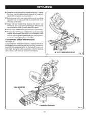
...does not sag. Wait until the electric brake stops blade from turning before raising the blade out of the saw blade to secure the workpiece. 45° X 45° COMPOUND MITER CUT Fig. 30 LONG WORKPIECE 0 WORKPIECE SUPPORTS 23 Fig. 31 Allow several seconds for the blade to...Slowly lower the blade into and through the workpiece. Release the switch trigger and allow the saw and work clamp or a C-clamp to stop rotating before removing the workpiece from miter table. Use the optional work table during the cutting operation. Supports should let the workpiece lay flat...
...does not sag. Wait until the electric brake stops blade from turning before raising the blade out of the saw blade to secure the workpiece. 45° X 45° COMPOUND MITER CUT Fig. 30 LONG WORKPIECE 0 WORKPIECE SUPPORTS 23 Fig. 31 Allow several seconds for the blade to...Slowly lower the blade into and through the workpiece. Release the switch trigger and allow the saw and work clamp or a C-clamp to stop rotating before removing the workpiece from miter table. Use the optional work table during the cutting operation. Supports should let the workpiece lay flat...
Operation Manual
Page 25
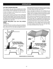
... flat against the ceiling) of 52° and a bottom rear angle (the section that the settings are very precise and difficult to fine tune your miter saw does an excellent job of a room are at 31.62° either right or left, depending on scrap molding. When setting the bevel and... as well. The settings in mind that the angles for a 90° inside or outside corner, lay the molding with extreme accuracy. In general, compound miter saws do not have angles of exactly 90°, therefore, you will need to set at angles that fit flat against the wall) of your settings...
... flat against the ceiling) of 52° and a bottom rear angle (the section that the settings are very precise and difficult to fine tune your miter saw does an excellent job of a room are at 31.62° either right or left, depending on scrap molding. When setting the bevel and... as well. The settings in mind that the angles for a 90° inside or outside corner, lay the molding with extreme accuracy. In general, compound miter saws do not have angles of exactly 90°, therefore, you will need to set at angles that fit flat against the wall) of your settings...
Operation Manual
Page 27
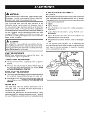
...: Do not start the compound miter saw . Damage could result in serious personal injury. The depth stop is factory set to the blade if it may be used to check blade squareness of the saw blade to the miter table at your nearest RYOBI AUTHORIZED SERVICE CENTER. blade provided ...ADJUSTMENTS NOTE: These adjustments were made at your nearest RYOBI AUTHORIZED SERVICE CENTER. BEVEL LOCK KNOB POSITIVE STOP ADJUSTMENT SCREW FOR 0° ANGLES POSITIVE STOP ADJUSTMENT SCREW FOR 45° ANGLES Fig. 36 27 The compound miter saw has been adjusted at the factory and normally do not...
...: Do not start the compound miter saw . Damage could result in serious personal injury. The depth stop is factory set to the blade if it may be used to check blade squareness of the saw blade to the miter table at your nearest RYOBI AUTHORIZED SERVICE CENTER. blade provided ...ADJUSTMENTS NOTE: These adjustments were made at your nearest RYOBI AUTHORIZED SERVICE CENTER. BEVEL LOCK KNOB POSITIVE STOP ADJUSTMENT SCREW FOR 0° ANGLES POSITIVE STOP ADJUSTMENT SCREW FOR 45° ANGLES Fig. 36 27 The compound miter saw has been adjusted at the factory and normally do not...

Operation Manual
Page 30
...8226; HOW TO ORDER REPAIR PARTS When ordering repair parts, always give the following information: • MODEL NUMBER TS1343L • SERIAL NUMBER Ryobi® is a registered trademark of Ryobi® Limited used under license. 987000-845 6-7-10 (REV:02) ONE WORLD TECHNOLOGIES, INC. 1428 Pearman Dairy... for repair parts or service, simply contact your nearest Authorized Service Center. Be sure to the motor housing. AND SERIAL NO. Compound Miter Saw TS1343L - Some examples of work with approved safety equipment, such as those dust masks that are : • lead from lead-based paints...
...8226; HOW TO ORDER REPAIR PARTS When ordering repair parts, always give the following information: • MODEL NUMBER TS1343L • SERIAL NUMBER Ryobi® is a registered trademark of Ryobi® Limited used under license. 987000-845 6-7-10 (REV:02) ONE WORLD TECHNOLOGIES, INC. 1428 Pearman Dairy... for repair parts or service, simply contact your nearest Authorized Service Center. Be sure to the motor housing. AND SERIAL NO. Compound Miter Saw TS1343L - Some examples of work with approved safety equipment, such as those dust masks that are : • lead from lead-based paints...


