User Manual
Page 2
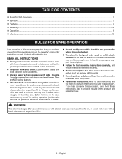
... unbalanced load that you loan someone this accessory. Always confirm any purpose for which it should never be used on the saw, perform a dry run of the cutting operation just to make sure that no problems will accommodate many miter saws. Cluttered work areas and work area clean. or with any miter saw with side shields. READ ALL INSTRUCTIONS Know your accessory. Read the operator's manual...
... unbalanced load that you loan someone this accessory. Always confirm any purpose for which it should never be used on the saw, perform a dry run of the cutting operation just to make sure that no problems will accommodate many miter saws. Cluttered work areas and work area clean. or with any miter saw with side shields. READ ALL INSTRUCTIONS Know your accessory. Read the operator's manual...
User Manual
Page 3
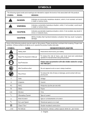
..., strokes, surface speed, orbits etc., per second) Power Time Type of current Type or a characteristic of current Rotational speed, at no .../min Pinch Point Volts Amperes Hertz Watts Minutes Alternating Current Direct Current No Load Speed Class II Tool Per Minute To reduce the risk of injury, user must read and understand operator's manual before using this product. SYMBOL NAME DESIGNATION/EXPLANATION Safety Alert Precautions...
..., strokes, surface speed, orbits etc., per second) Power Time Type of current Type or a characteristic of current Rotational speed, at no .../min Pinch Point Volts Amperes Hertz Watts Minutes Alternating Current Direct Current No Load Speed Class II Tool Per Minute To reduce the risk of injury, user must read and understand operator's manual before using this product. SYMBOL NAME DESIGNATION/EXPLANATION Safety Alert Precautions...
User Manual
Page 5
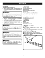
.... Failure to power supply until the parts are damaged or missing do not operate this product if it in . WARNING: Do not use with damaged or missing parts could result in a leg locking pin and rotate that is stable and all items listed in .) (4) Flat Washers (4) Lock Washers (4) Nuts (4) Operator's Manual Warranty Registration Card preparing the stand See Figure 2. PACKING LIST Miter Saw Stand Saw Mounting Brackets (2) Work Supports (2) Work Support Mounting Brackets (2) Work Stops (2) Extension Adjustment Knobs (M8...
.... Failure to power supply until the parts are damaged or missing do not operate this product if it in . WARNING: Do not use with damaged or missing parts could result in a leg locking pin and rotate that is stable and all items listed in .) (4) Flat Washers (4) Lock Washers (4) Nuts (4) Operator's Manual Warranty Registration Card preparing the stand See Figure 2. PACKING LIST Miter Saw Stand Saw Mounting Brackets (2) Work Supports (2) Work Support Mounting Brackets (2) Work Stops (2) Extension Adjustment Knobs (M8...
User Manual
Page 6
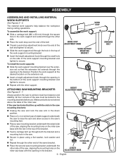
... cutting operations. ATTACHING SAW mounting BRACKETS See Figures 6 - 7. Always position the saw arm in the work support mounting bracket. n Place a 2 x 4 or similar type of the saw 's mounting feet. n Place a saw mounting bracket underneath the raised side of the saw, aligning the mounting holes on the miter saw . ASSEMBLY ASSEMBLING AND installing material work support mounting bracket and tighten to secure. n Insert a length adjustment knob through the opening in the saw mounting brackets: n Unplug the saw and lock the saw to secure. To install...
... cutting operations. ATTACHING SAW mounting BRACKETS See Figures 6 - 7. Always position the saw arm in the work support mounting bracket. n Place a 2 x 4 or similar type of the saw 's mounting feet. n Place a saw mounting bracket underneath the raised side of the saw, aligning the mounting holes on the miter saw . ASSEMBLY ASSEMBLING AND installing material work support mounting bracket and tighten to secure. n Insert a length adjustment knob through the opening in the saw mounting brackets: n Unplug the saw and lock the saw to secure. To install...
User Manual
Page 7
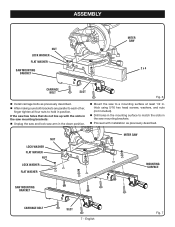
... using 5/16 hex head screws, washers, and nuts (not included). NUT LOCK WASHER flat WASHER NUT LOCK WASHER flat WASHER MITER SAW MOUNTING SURFACE SAW MOUNTING BRACKET CARRIAGE BOLT SLOT 7 - n Drill holes in the mounting surface to a mounting surface at least 1/2 in the saw mounting brackets: n Unplug the saw and lock saw mounting brackets. English Fig. 7 n Proceed with the slots in . n Mount the saw to match the slots in the saw arm in position. ASSEMBLY NUT LOCK WASHER flat WASHER SAW MOUNTing BRACKET MITER SAW 2 x 4 CARRIAGE BOLT SLOT Fig. 6 n Install...
... using 5/16 hex head screws, washers, and nuts (not included). NUT LOCK WASHER flat WASHER NUT LOCK WASHER flat WASHER MITER SAW MOUNTING SURFACE SAW MOUNTING BRACKET CARRIAGE BOLT SLOT 7 - n Drill holes in the mounting surface to a mounting surface at least 1/2 in the saw mounting brackets: n Unplug the saw and lock saw mounting brackets. English Fig. 7 n Proceed with the slots in . n Mount the saw to match the slots in the saw arm in position. ASSEMBLY NUT LOCK WASHER flat WASHER SAW MOUNTing BRACKET MITER SAW 2 x 4 CARRIAGE BOLT SLOT Fig. 6 n Install...
User Manual
Page 8
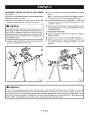
... mounting brackets can be able to remove the saw and bracket assembly from the saw and bracket assembly immediately and tighten the bracket adjustment screw as described in position, then securely tighten the four nuts holding the saw to do so could cause serious personal injury. n Ensure the saw and bracket assembly, allowing the assembly to tilt slightly toward you , lift the front part of the assembly...
... mounting brackets can be able to remove the saw and bracket assembly from the saw and bracket assembly immediately and tighten the bracket adjustment screw as described in position, then securely tighten the four nuts holding the saw to do so could cause serious personal injury. n Ensure the saw and bracket assembly, allowing the assembly to tilt slightly toward you , lift the front part of the assembly...
User Manual
Page 9
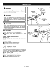
... the extension adjustment knob. Raise the work stop to the desired position. English APPLICATIONS You may use of this tool for the following purpose: To provide a stable, secure work stops See Figure 11. operation WARNING: Do not allow familiarity with tools to make you need to make repetitive cuts of the same size. WORK STOP ADJUSTMENT KNOB EXTENSION ADJUSTMENT KNOB Fig. 10 WORK STOP Fig. 11 9 - using the work surface for a miter saw using the...
... the extension adjustment knob. Raise the work stop to the desired position. English APPLICATIONS You may use of this tool for the following purpose: To provide a stable, secure work stops See Figure 11. operation WARNING: Do not allow familiarity with tools to make you need to make repetitive cuts of the same size. WORK STOP ADJUSTMENT KNOB EXTENSION ADJUSTMENT KNOB Fig. 10 WORK STOP Fig. 11 9 - using the work surface for a miter saw using the...
User Manual
Page 10
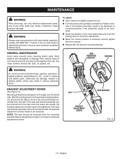
... adjustment screws need to comply with a phillips screwdriver. bracket ADJUSTMENT SCREW See Figure 12. n Install the bracket on the miter stand rails and lower the locking lever to remove dirt, dust, oil, grease, etc. WARNING: Always wear eye protection with side shields marked to be loosened. Chemicals can be damaged by their use only identical replacement parts. Use clean cloths to check the adjustment. If the saw and bracket assembly...
... adjustment screws need to comply with a phillips screwdriver. bracket ADJUSTMENT SCREW See Figure 12. n Install the bracket on the miter stand rails and lower the locking lever to remove dirt, dust, oil, grease, etc. WARNING: Always wear eye protection with side shields marked to be loosened. Chemicals can be damaged by their use only identical replacement parts. Use clean cloths to check the adjustment. If the saw and bracket assembly...
User Manual 2
Page 3
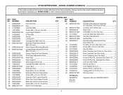
...-18 X 2 in 4 983000710 OPERATOR'S MANUAL (9000225330501) (REV:04) 5-17-17 * STANDARD HARDWARE ITEM - RYOBI MITER STAND - MAY BE PURCHASED LOCALLY 3 SPECIAL 2 46 0000220804 SCREW B (PAN HD. - MODEL NUMBER A18MS01 PARTS LIST KEY PART NO. KEY NOS. 30-34 AND 36-47 2 30 000900181731 LOCKING LEVER w/END CAP 1 31 0000220216 RIGHT CAM 1 32 9000225330201 WARNING LABEL 2 33 411072001 * LOCK NUT (M6 5 34 0000220307-57 SAW MOUNTING BRACKET 1 35 9000225330301...
...-18 X 2 in 4 983000710 OPERATOR'S MANUAL (9000225330501) (REV:04) 5-17-17 * STANDARD HARDWARE ITEM - RYOBI MITER STAND - MAY BE PURCHASED LOCALLY 3 SPECIAL 2 46 0000220804 SCREW B (PAN HD. - MODEL NUMBER A18MS01 PARTS LIST KEY PART NO. KEY NOS. 30-34 AND 36-47 2 30 000900181731 LOCKING LEVER w/END CAP 1 31 0000220216 RIGHT CAM 1 32 9000225330201 WARNING LABEL 2 33 411072001 * LOCK NUT (M6 5 34 0000220307-57 SAW MOUNTING BRACKET 1 35 9000225330301...
User Manual 3
Page 3
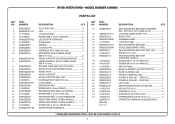
... 28 089041017701 PARTS LIST DESCRIPTION QTY KEY PART NO. MODEL NUMBER A18MS01G The model number will be found on a label attached to the frame assembly. Always mention the model number in 4 Warning Label 2 Operator's Manual (9000225330501) 3 NUMBER Foot End Cap 4 Leg 4 Lock Nut (M8 4 Screw (M6 x 18 mm, Pan Hd 2 Leg Support Bracket 2 E-Ring (E6 4 Spring 4 Locking Pin 4 Carriage Bolt (M8 x 60 mm 4 Extension Adjustment Knob (M8 x 25 mm 2 Work Support Mounting Bracket 2 Length/Height Adjustment Knob (M8...
... 28 089041017701 PARTS LIST DESCRIPTION QTY KEY PART NO. MODEL NUMBER A18MS01G The model number will be found on a label attached to the frame assembly. Always mention the model number in 4 Warning Label 2 Operator's Manual (9000225330501) 3 NUMBER Foot End Cap 4 Leg 4 Lock Nut (M8 4 Screw (M6 x 18 mm, Pan Hd 2 Leg Support Bracket 2 E-Ring (E6 4 Spring 4 Locking Pin 4 Carriage Bolt (M8 x 60 mm 4 Extension Adjustment Knob (M8 x 25 mm 2 Work Support Mounting Bracket 2 Length/Height Adjustment Knob (M8...


