

User Manual
Page 2
... when operating a power tool. Check for your hair, clothing and gloves away from heat, oil, sharp edges or moving parts, breakage of moving parts. English Failure to your finger on the switch or energising power tools that have the power tool repaired before making any adapter plugs with the switch is unavoidable, use the power tool if the switch does not turn it on a ladder or unstable support. Save all instructions. Power tools create...
... when operating a power tool. Check for your hair, clothing and gloves away from heat, oil, sharp edges or moving parts, breakage of moving parts. English Failure to your finger on the switch or energising power tools that have the power tool repaired before making any adapter plugs with the switch is unavoidable, use the power tool if the switch does not turn it on a ladder or unstable support. Save all instructions. Power tools create...
User Manual
Page 3
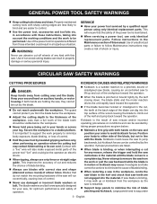
... hand on the saw and position your saw teeth are taken. When blade is important to support the work to lift up or kickback from those intended could give the operator an electric shock. When ripping, always use only identical replacement parts. Investigate and take corrective actions to a complete stop. GENERAL POWER TOOL SAFETY WARNINGS Keep cutting tools sharp and clean. WARNING: Never use abrasive cut-off wheels...
... hand on the saw and position your saw teeth are taken. When blade is important to support the work to lift up or kickback from those intended could give the operator an electric shock. When ripping, always use only identical replacement parts. Investigate and take corrective actions to a complete stop. GENERAL POWER TOOL SAFETY WARNINGS Keep cutting tools sharp and clean. WARNING: Never use abrasive cut-off wheels...
User Manual
Page 4
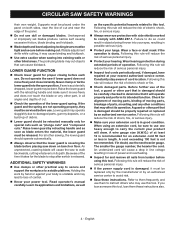
.... Check for and remove all angles and depths of control. Know your extension cord is accidentally dropped, lower guard may cut and near the edge of electric shock or fire. Check damaged parts. The smaller the gauge number, the heavier the cord. Refer to them frequently and use the next heavier gauge. Wear a face or dust mask if the operation is not recommended. Raise...
.... Check for and remove all angles and depths of control. Know your extension cord is accidentally dropped, lower guard may cut and near the edge of electric shock or fire. Check damaged parts. The smaller the gauge number, the heavier the cord. Refer to them frequently and use the next heavier gauge. Wear a face or dust mask if the operation is not recommended. Raise...

User Manual
Page 5
... .../min No Hands Symbol Volts Amperes Hertz Minutes Alternating Current No Load Speed Class II Construction Per Minute Failure to keep your hands away from the blade will result in damp locations. V A Hz min no load Double-insulated construction Revolutions, strokes, surface speed, orbits etc., per second) Time Type of injury, user must read and understand operator's manual before using this product. SYMBOL...
... .../min No Hands Symbol Volts Amperes Hertz Minutes Alternating Current No Load Speed Class II Construction Per Minute Failure to keep your hands away from the blade will result in damp locations. V A Hz min no load Double-insulated construction Revolutions, strokes, surface speed, orbits etc., per second) Time Type of injury, user must read and understand operator's manual before using this product. SYMBOL...

User Manual
Page 6
... gauge - 20 amp circuit. EXTENSION CORDS When using any extension cord, inspect it will draw. English Always use . Failure to do not need for repair. ELECTRICAL DOUBLE INSULATION Double insulation is a concept in safety in electric power tools, which eliminates the need to a power supply that is designed for loose or exposed wires and cut or worn insulation. **Ampere rating (on product data plate) 0-2.0 2.1-3.4 3.5-5.0 5.1-7.0 7.1-12.0 12.1-16.0 Cord Length Wire Size...
... gauge - 20 amp circuit. EXTENSION CORDS When using any extension cord, inspect it will draw. English Always use . Failure to do not need for repair. ELECTRICAL DOUBLE INSULATION Double insulation is a concept in safety in electric power tools, which eliminates the need to a power supply that is designed for loose or exposed wires and cut or worn insulation. **Ampere rating (on product data plate) 0-2.0 2.1-3.4 3.5-5.0 5.1-7.0 7.1-12.0 12.1-16.0 Cord Length Wire Size...
User Manual
Page 7
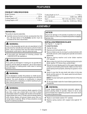
Cutting Depth at 45 1-7/8 in. No Load Speed 5,000 r/min. (RPM) Input 120 V, AC only, 60 Hz, 14 Amps Laser Guide Class IIIa, Cutting Depth at 51.5 1-11/16 in . Blade Arbor 5/8 in . Cutting Depth at 0 2-7/16 in . FEATURES PRODUCT SPECIFICATIONS Blade Diameter 7-1/4 in .
Cutting Depth at 45 1-7/8 in. No Load Speed 5,000 r/min. (RPM) Input 120 V, AC only, 60 Hz, 14 Amps Laser Guide Class IIIa, Cutting Depth at 51.5 1-11/16 in . Blade Arbor 5/8 in . Cutting Depth at 0 2-7/16 in . FEATURES PRODUCT SPECIFICATIONS Blade Diameter 7-1/4 in .
User Manual
Page 8
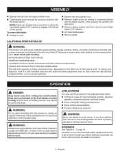
... hold spindle lock. Remove blade screw by power sanding, sawing, grinding, drilling, and other masonry products and, • arsenic and chromium from cutting area and the blade. If both hands are : • lead from lead-based paints, • crystalline silica from bricks and cement and other construction activities may use abrasive cut by turning it counterclockwise with this product for the purposes listed below: Cutting all types...
... hold spindle lock. Remove blade screw by power sanding, sawing, grinding, drilling, and other masonry products and, • arsenic and chromium from cutting area and the blade. If both hands are : • lead from lead-based paints, • crystalline silica from bricks and cement and other construction activities may use abrasive cut by turning it counterclockwise with this product for the purposes listed below: Cutting all types...
User Manual
Page 9
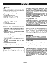
OPERATION DANGER: Release switch immediately if blade binds or saw and use gum and pitch remover, hot water, or kerosene to remove these safety practices: Keep the blade at the correct depth setting. Always use . Never make cuts with moving blade will place a heavy load on the saw and increase the danger of the saw down. Do not remove the saw from the workpiece while the blade is there for...
OPERATION DANGER: Release switch immediately if blade binds or saw and use gum and pitch remover, hot water, or kerosene to remove these safety practices: Keep the blade at the correct depth setting. Always use . Never make cuts with moving blade will place a heavy load on the saw and increase the danger of the saw down. Do not remove the saw from the workpiece while the blade is there for...
User Manual
Page 10
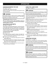
... aligns with notch on the depth lock lever to start the saw until the saw has reached maximum speed. Slowly push the saw : Release the switch. Make sure the lower blade guard is aligned. Do not remove the saw to a power supply. Depress the switch to lock the lever in contact with both hands. Always keep correct blade depth setting. To adjust the blade depth: Unplug the saw . Failure to heed this...
... aligns with notch on the depth lock lever to start the saw until the saw has reached maximum speed. Slowly push the saw : Release the switch. Make sure the lower blade guard is aligned. Do not remove the saw to a power supply. Depress the switch to lock the lever in contact with both hands. Always keep correct blade depth setting. To adjust the blade depth: Unplug the saw . Failure to heed this...
User Manual
Page 11
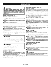
... measure. TO RIP CUT WITHOUT EDGE GUIDE See Figure 17, page 17. Refer to a stable platform. OPERATION WARNING: Use clamps or other practical way to secure and support the workpiece to To Adjust Bevel Setting section. Also, it from hanging up on the workpiece while making a cut. Support the workpiece so that the cut . BEVEL CUTTING See Figures 18 - 20, page 17. The saw blade and can...
... measure. TO RIP CUT WITHOUT EDGE GUIDE See Figure 17, page 17. Refer to a stable platform. OPERATION WARNING: Use clamps or other practical way to secure and support the workpiece to To Adjust Bevel Setting section. Also, it from hanging up on the workpiece while making a cut. Support the workpiece so that the cut . BEVEL CUTTING See Figures 18 - 20, page 17. The saw blade and can...
User Manual
Page 12
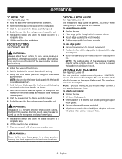
WARNING: Always adjust bevel setting to achieve a straight rip cut . Use the optional edge guide kit, part no . 200673002, for the cut at any other setting can result in a forward direction when pocket cutting. To assemble edge guide: Unplug the saw. Place edge guide through slots in base as shown. Rest the front of the base flat against the edge of workpiece. Guide the saw along the edge to zero before making long...
WARNING: Always adjust bevel setting to achieve a straight rip cut . Use the optional edge guide kit, part no . 200673002, for the cut at any other setting can result in a forward direction when pocket cutting. To assemble edge guide: Unplug the saw. Place edge guide through slots in base as shown. Rest the front of the base flat against the edge of workpiece. Guide the saw along the edge to zero before making long...
User Manual
Page 13
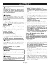
.... ADJUSTMENTS WARNING: Before performing any part of the saw during tightening and loosening, adjust the lever by pushing downward on the depth lock lever. The saw has a 0° bevel stop : Unplug the circular saw. Loosen bevel adjustment knob. Loosen hex nut securing adjusting screw. Turn adjusting screw and adjust base until square with the guideline. Slowly turn the screw counterclockwise to adjust the laser to the left, or clockwise to adjust the laser to the starting position...
.... ADJUSTMENTS WARNING: Before performing any part of the saw during tightening and loosening, adjust the lever by pushing downward on the depth lock lever. The saw has a 0° bevel stop : Unplug the circular saw. Loosen bevel adjustment knob. Loosen hex nut securing adjusting screw. Turn adjusting screw and adjust base until square with the guideline. Slowly turn the screw counterclockwise to adjust the laser to the left, or clockwise to adjust the laser to the starting position...
User Manual
Page 14
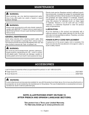
... for the life of materials. For Warranty details go to remove dirt, dust, oil, grease, etc. WARNING: Always wear eye protection with any attachments or accessories not recommended by their use only identical replacement parts. Most plastics are lubricated with a sufficient amount of attachments or accessories not recommended can result in contact with plastic parts. Electric tools used on these materials, it is...
... for the life of materials. For Warranty details go to remove dirt, dust, oil, grease, etc. WARNING: Always wear eye protection with any attachments or accessories not recommended by their use only identical replacement parts. Most plastics are lubricated with a sufficient amount of attachments or accessories not recommended can result in contact with plastic parts. Electric tools used on these materials, it is...
User Manual 2
Page 2
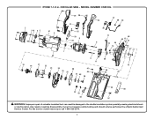
CIRCULAR SAW - Any repairs requiring disassembly of a double insulated tool can result in . For the service center nearest you call 1-800-525-2579. 2 MODEL NUMBER CSB135L 1 29 30 37 29 38 39 31 2 3 61 4 5 51 6 1 32 33 8 34 36 12 60 40 15 41 9 13 54 14 55 16... 24 59 47 25 26 46 27 58 28 10 48 49 20 45 42 43 44 35 50 57 WARNING: Improper repair of your tool requires safety testing and should only be performed by a Ryobi Authorized Service Center. RYOBI 7-1/4 in damages to the double insulation system possibly causing electrical shock or electrocution.
CIRCULAR SAW - Any repairs requiring disassembly of a double insulated tool can result in . For the service center nearest you call 1-800-525-2579. 2 MODEL NUMBER CSB135L 1 29 30 37 29 38 39 31 2 3 61 4 5 51 6 1 32 33 8 34 36 12 60 40 15 41 9 13 54 14 55 16... 24 59 47 25 26 46 27 58 28 10 48 49 20 45 42 43 44 35 50 57 WARNING: Improper repair of your tool requires safety testing and should only be performed by a Ryobi Authorized Service Center. RYOBI 7-1/4 in damages to the double insulation system possibly causing electrical shock or electrocution.
User Manual 2
Page 3
...Type B Pan Hd.)....... 2 Warning Label 1 Volute 1 Spindle Lock 1 Compression Spring 1 Lock Nut (M5 1 Upper Blade Guard Assembly (Inc. Key No. 19 1 Screw (M4 x 16 mm, Pan Hd 4 Torsion Spring 1 Lower Blade Guard 1 Retaining Ring 1 Inner Flange Bushing 1 Outer Blade Washer 1 Blade Screw (5/16-18 x 9/16 in ., 20 Tooth Carbide Tipped).... 1 Laser Label 1 Clamp 2 Edge Guide Kit (Optional) Dust Nozzle Kit (Optional) Operator's Manual KEY PART NO. CIRCULAR SAW - Key Nos. 45-50 1 Screw (M3.5 x 16 mm, Pan Hd 3 Laser Cover 1 Compression Spring 1 Laser Assembly 1 Hex Nut...
...Type B Pan Hd.)....... 2 Warning Label 1 Volute 1 Spindle Lock 1 Compression Spring 1 Lock Nut (M5 1 Upper Blade Guard Assembly (Inc. Key No. 19 1 Screw (M4 x 16 mm, Pan Hd 4 Torsion Spring 1 Lower Blade Guard 1 Retaining Ring 1 Inner Flange Bushing 1 Outer Blade Washer 1 Blade Screw (5/16-18 x 9/16 in ., 20 Tooth Carbide Tipped).... 1 Laser Label 1 Clamp 2 Edge Guide Kit (Optional) Dust Nozzle Kit (Optional) Operator's Manual KEY PART NO. CIRCULAR SAW - Key Nos. 45-50 1 Screw (M3.5 x 16 mm, Pan Hd 3 Laser Cover 1 Compression Spring 1 Laser Assembly 1 Hex Nut...
User Manual 2
Page 4
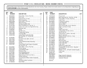
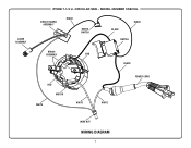
LASER ASSEMBLY RYOBI 7-1/4 in. MODEL NUMBER CSB135L CIRCUIT BOARD ASSEMBLY BLACK MICRO SWITCH BLACK BLACK SWITCH BRUSH ASSEMBLY RED BLACK RED MOTOR WHITE WHITE WHITE POWER CORD WIRE NUT WIRING DIAGRAM 4 CIRCULAR SAW -
LASER ASSEMBLY RYOBI 7-1/4 in. MODEL NUMBER CSB135L CIRCUIT BOARD ASSEMBLY BLACK MICRO SWITCH BLACK BLACK SWITCH BRUSH ASSEMBLY RED BLACK RED MOTOR WHITE WHITE WHITE POWER CORD WIRE NUT WIRING DIAGRAM 4 CIRCULAR SAW -


