English Manual
Page 1
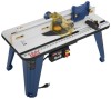
Thank you years of rugged, trouble-free performance. SAVE THIS MANUAL FOR FUTURE REFERENCE When properly cared for, it will give you for dependability, ease of injury, the user must read and understand the operator's manual before using this product. OPERATOR'S MANUAL ROUTER TABLE A25RT02 3 2 1 0 1 Inch inch 3 2 1 0 1 Inch Your router table has been engineered and manufactured to our high standard for your purchase. WARNING: To reduce the risk of operation, and operator safety.
Thank you years of rugged, trouble-free performance. SAVE THIS MANUAL FOR FUTURE REFERENCE When properly cared for, it will give you for dependability, ease of injury, the user must read and understand the operator's manual before using this product. OPERATOR'S MANUAL ROUTER TABLE A25RT02 3 2 1 0 1 Inch inch 3 2 1 0 1 Inch Your router table has been engineered and manufactured to our high standard for your purchase. WARNING: To reduce the risk of operation, and operator safety.

English Manual
Page 2
...; Specific Safety Rules...4 Symbols...5-6 Electrical ...7 Features...8-9 Assembly ...10-16 Operation...17-18 Maintenance ...19 Parts Ordering / Service ...Back Page INTRODUCTION This product has many features for a particular purpose, are limited to two years from the date of purchase. Safety, performance, and dependability have other rights which it easy to maintain and operate. The replacement power tool...
...; Specific Safety Rules...4 Symbols...5-6 Electrical ...7 Features...8-9 Assembly ...10-16 Operation...17-18 Maintenance ...19 Parts Ordering / Service ...Back Page INTRODUCTION This product has many features for a particular purpose, are limited to two years from the date of purchase. Safety, performance, and dependability have other rights which it easy to maintain and operate. The replacement power tool...
English Manual
Page 3
... moving parts, binding of parts, mounting and any tool. USE RECOMMENDED ACCESSORIES. Follow instructions for better and safer performance. Consult the operator's manual for an extension cord 25 feet or less in doubt, use only extension cords marked "W-A" or "W". Wear a face or dust mask if the operation is in electric shock, fire and/or serious personal injury. When tool is tipped. CHECK DAMAGED PARTS. A wire gauge size (A.W.G.) of...
... moving parts, binding of parts, mounting and any tool. USE RECOMMENDED ACCESSORIES. Follow instructions for better and safer performance. Consult the operator's manual for an extension cord 25 feet or less in doubt, use only extension cords marked "W-A" or "W". Wear a face or dust mask if the operation is in electric shock, fire and/or serious personal injury. When tool is tipped. CHECK DAMAGED PARTS. A wire gauge size (A.W.G.) of...
English Manual
Page 4
... WHEN NECESSARY. ALWAYS SUPPORT WORKPIECE FIRMLY AGAINST TABLE AND FENCE. IF THE POWER SUPPLY CORD IS DAMAGED, it well away from the rotating blade. INSPECT EXTENSION CORDS PERIODICALLY and replace if damaged. KEEP TOOL DRY, CLEAN, AND FREE FROM OIL AND GREASE. Instructions for safe use only identical replacement parts. SPECIFIC SAFETY RULES FOR YOUR OWN SAFETY, read this tool, loan them to a live...
... WHEN NECESSARY. ALWAYS SUPPORT WORKPIECE FIRMLY AGAINST TABLE AND FENCE. IF THE POWER SUPPLY CORD IS DAMAGED, it well away from the rotating blade. INSPECT EXTENSION CORDS PERIODICALLY and replace if damaged. KEEP TOOL DRY, CLEAN, AND FREE FROM OIL AND GREASE. Instructions for safe use only identical replacement parts. SPECIFIC SAFETY RULES FOR YOUR OWN SAFETY, read this tool, loan them to a live...

English Manual
Page 5
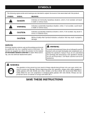
... product. Read The Operator's Manual Eye Protection Safety Alert No Hands Symbol No Hands Symbol No Hands Symbol No Hands Symbol Hot Surface To reduce the risk of current Rotational speed, at no No Load Speed Type or a characteristic of injury, user must read and understand operator's manual before using this product. Please study them and learn their meaning. SYMBOL NAME DESIGNATION/EXPLANATION V Volts Voltage A Amperes...
... product. Read The Operator's Manual Eye Protection Safety Alert No Hands Symbol No Hands Symbol No Hands Symbol No Hands Symbol Hot Surface To reduce the risk of current Rotational speed, at no No Load Speed Type or a characteristic of injury, user must read and understand operator's manual before using this product. Please study them and learn their meaning. SYMBOL NAME DESIGNATION/EXPLANATION V Volts Voltage A Amperes...
English Manual
Page 6
... avoided, could result in death or serious injury. If you do not use only identical replacement parts. Before beginning power tool operation, always wear safety goggles or safety glasses with this product. CAUTION: (Without Safety Alert Symbol) Indicates a situation that may result in severe eye damage. SAVE THESE INSTRUCTIONS 6 SYMBOLS The following signal words and meanings are intended to explain...
... avoided, could result in death or serious injury. If you do not use only identical replacement parts. Before beginning power tool operation, always wear safety goggles or safety glasses with this product. CAUTION: (Without Safety Alert Symbol) Indicates a situation that may result in severe eye damage. SAVE THESE INSTRUCTIONS 6 SYMBOLS The following signal words and meanings are intended to explain...
English Manual
Page 7
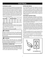
.... This is designed for lights cannot properly carry a power product motor. ELECTRICAL EXTENSION CORDS Use only 3-wire extension cords that have the proper outlet installed by a qualified electrician. NOTE: AWG = American Wire Gauge When working area. Do not modify the plug provided. If the router table does not operate when plugged into a matching outlet that is not constant and decreases under a load or with insulation having...
.... This is designed for lights cannot properly carry a power product motor. ELECTRICAL EXTENSION CORDS Use only 3-wire extension cords that have the proper outlet installed by a qualified electrician. NOTE: AWG = American Wire Gauge When working area. Do not modify the plug provided. If the router table does not operate when plugged into a matching outlet that is not constant and decreases under a load or with insulation having...
English Manual
Page 8
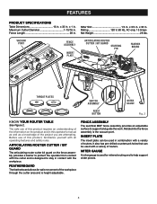
...routing and to help support wider pieces. 8 x 32 in . VACUUM PORT FENCE ASSEMBLY INSERT PLATE ARTICULATING ROUTER CUTTER / BIT GUARD STARTING PIN 3 2 1 0 1 Inch FEATHER BOARD inch 3 2 1 0 1 Inch RESE T PUSH THROAT PLATES SWITCH ASSEMBLY RESET BUTTON MITER GAUGE Fig. 2 KNOW YOUR ROUTER TABLE See Figure 2. FENCE ASSEMBLY The sacrifical MDF fence assembly provides an adjustable surface to stay in . 1 Inch FEDEIDRECTION FEATURES PRODUCT SPECIFICATIONS Table Dimensions 16 in . MITER GAUGE A miter gauge is designed to support and guide the work. Maximum Cutter Diameter 1-15...
...routing and to help support wider pieces. 8 x 32 in . VACUUM PORT FENCE ASSEMBLY INSERT PLATE ARTICULATING ROUTER CUTTER / BIT GUARD STARTING PIN 3 2 1 0 1 Inch FEATHER BOARD inch 3 2 1 0 1 Inch RESE T PUSH THROAT PLATES SWITCH ASSEMBLY RESET BUTTON MITER GAUGE Fig. 2 KNOW YOUR ROUTER TABLE See Figure 2. FENCE ASSEMBLY The sacrifical MDF fence assembly provides an adjustable surface to stay in . 1 Inch FEDEIDRECTION FEATURES PRODUCT SPECIFICATIONS Table Dimensions 16 in . MITER GAUGE A miter gauge is designed to support and guide the work. Maximum Cutter Diameter 1-15...
English Manual
Page 9
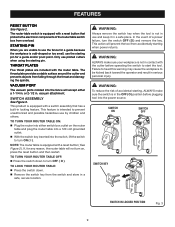
... ( O ) position before operating the switch to use and keep it in locking feature. In the event of a power failure, turn on the router table and plug the router table into a 120 volt grounded outlet. With the switch key inserted into the power source. This action will not turn the switch OFF ( O ) and remove the key. WARNING: To reduce the risk of the router table switch box from accidentally starting pin. Only use by children...
... ( O ) position before operating the switch to use and keep it in locking feature. In the event of a power failure, turn on the router table and plug the router table into a 120 volt grounded outlet. With the switch key inserted into the power source. This action will not turn the switch OFF ( O ) and remove the key. WARNING: To reduce the risk of the router table switch box from accidentally starting pin. Only use by children...

English Manual
Page 10
... personal injury. 1 2 3 4 3 2 1 0 1 Inch 5 6 8 7 9 10 PACKING LIST 1. WARNING: If any accessories from the box. Failure to do not operate this product until the parts are replaced. Table Leg (4) 2. Starting Pin 3. Table Top 5. Switch Box 8. Carriage Bolt Washer (2) 9. Carriage Bolt (2) 10. Hex Key (1) 11. Throat Plates (5) 13. Router Insert Plate Screws (10-32 x 5/8 in accidental starting and possible serious personal injury. Fence Lock Knobs (2) 20. Featherboard 21. Fence Lock Knob Washer (2) 23. Featherboard Lock Knobs (2) 24. Operator's Manual (not shown...
... personal injury. 1 2 3 4 3 2 1 0 1 Inch 5 6 8 7 9 10 PACKING LIST 1. WARNING: If any accessories from the box. Failure to do not operate this product until the parts are replaced. Table Leg (4) 2. Starting Pin 3. Table Top 5. Switch Box 8. Carriage Bolt Washer (2) 9. Carriage Bolt (2) 10. Hex Key (1) 11. Throat Plates (5) 13. Router Insert Plate Screws (10-32 x 5/8 in accidental starting and possible serious personal injury. Fence Lock Knobs (2) 20. Featherboard 21. Fence Lock Knob Washer (2) 23. Featherboard Lock Knobs (2) 24. Operator's Manual (not shown...
English Manual
Page 11
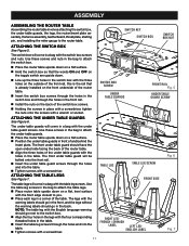
... under table guard screws. SWITCH KEY SWITCH BOX SWITCH BOX NUT SWITCH BOX SCREW UNDER TABLE GUARDS FRONT RAIL Fig. 5 UNDER TABLE GUARD SCREW TABLE LEG TABLE LEG SCREW Fig. 6 FRONT SIDE RIGHT LEG- The front under table guard will be bolted onto the front rail. Insert the under table guards, the legs, the router/insert plate assembly, the fence assembly, featherboard, throat plate, starting pin, and installing the miter gauge to the router table. The table legs will come in a bag with the under table guards will come...
... under table guard screws. SWITCH KEY SWITCH BOX SWITCH BOX NUT SWITCH BOX SCREW UNDER TABLE GUARDS FRONT RAIL Fig. 5 UNDER TABLE GUARD SCREW TABLE LEG TABLE LEG SCREW Fig. 6 FRONT SIDE RIGHT LEG- The front under table guard will be bolted onto the front rail. Insert the under table guards, the legs, the router/insert plate assembly, the fence assembly, featherboard, throat plate, starting pin, and installing the miter gauge to the router table. The table legs will come in a bag with the under table guards will come...
English Manual
Page 12
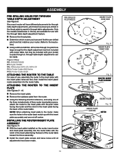
... router and the notch in the insert plate facing the back of use with the insert plate removed first, then install the insert plate/ router assembly into the router table with the notch in the insert plate facing the back of the router table toward the fence assembly. Install the insert plate screws and leave loose until all adjustments have and find the pre-drilled pilot hole that matches your router) to the key below in the key...
... router and the notch in the insert plate facing the back of use with the insert plate removed first, then install the insert plate/ router assembly into the router table with the notch in the insert plate facing the back of the router table toward the fence assembly. Install the insert plate screws and leave loose until all adjustments have and find the pre-drilled pilot hole that matches your router) to the key below in the key...
English Manual
Page 14
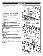
... make the insert plate level. Tighten insert plate screws with a screwdriver. SLOT CARRIAGE BOLT WASHER CARRIAGE BOLTS THROAT PLATE Fig. 13 TAB 3 2 1 0 1 Inch NOTCH 1 Inch 3 2 1 0 Fig. 14 DIFREEECDTION 14 Do not use if snaps are damaged or throat plates do so could result in serious personal injury. of the outermost edge of the cutter. HEX KEY ADJUSTING SCREWS DIFREEECDTION 3 2 1 0 1 Inch Fig. 12 FENCE FENCE LOCK KNOBS ASSEMBLY 1 Inch 0 3 2 1 0 WARNING: Make sure throat plates snap...
... make the insert plate level. Tighten insert plate screws with a screwdriver. SLOT CARRIAGE BOLT WASHER CARRIAGE BOLTS THROAT PLATE Fig. 13 TAB 3 2 1 0 1 Inch NOTCH 1 Inch 3 2 1 0 Fig. 14 DIFREEECDTION 14 Do not use if snaps are damaged or throat plates do so could result in serious personal injury. of the outermost edge of the cutter. HEX KEY ADJUSTING SCREWS DIFREEECDTION 3 2 1 0 1 Inch Fig. 12 FENCE FENCE LOCK KNOBS ASSEMBLY 1 Inch 0 3 2 1 0 WARNING: Make sure throat plates snap...

English Manual
Page 15
...61550; Unplug the router table and/or the router. Insert the featherboard bolts through the slots in the fence assembly. Slide the featherboard over the featherboard bolts. Install the fence lock knobs and carriage bolt washers over the carriage bolts. Tighten the fence lock knobs. FENCE LOCK KNOB 3 2 1 MITER GAUGE BAR SLOT FEATHERBOARD BOLT 3 2 1 0 1 Inch FEATHERBOARD CARRIAGE BOLT WASHER Fig. 15 STARTING PIN INSTALL STARTING PIN HOLES REMOVE 3 2 1 0 1 Inch DIF Fig. 16 MITER GAUGE 3 2 1 0 1 Inch POINTER 3 2 1 0 DIFREEECDTION...
...61550; Unplug the router table and/or the router. Insert the featherboard bolts through the slots in the fence assembly. Slide the featherboard over the featherboard bolts. Install the fence lock knobs and carriage bolt washers over the carriage bolts. Tighten the fence lock knobs. FENCE LOCK KNOB 3 2 1 MITER GAUGE BAR SLOT FEATHERBOARD BOLT 3 2 1 0 1 Inch FEATHERBOARD CARRIAGE BOLT WASHER Fig. 15 STARTING PIN INSTALL STARTING PIN HOLES REMOVE 3 2 1 0 1 Inch DIF Fig. 16 MITER GAUGE 3 2 1 0 1 Inch POINTER 3 2 1 0 DIFREEECDTION...

English Manual
Page 16
... flat washers, lock washers, and hex nuts (not included). 1 Inch FEDEIDRECTION VACUUM PORT 3 2 1 0 1 Inch VACUUM HOSE Fig. 18 inch 3 2 1 0 1 Inch WORK TABLE 3 2 1 0 1 Inch CLAMP Fig. 19 BOLTS inch 3 2 1 0 1 Inch FLAT WASHER HEX NUT 16 LOCK WASHER WORK TABLE Fig. 20 The vacuum port molded into the fence will accept either a 1-1/4 in . NOTE: Position the router table surface at approximately hip height. Insert four bolts (not included, 1/4-20 recommended) and tighten securely with a pencil. Remove the router table. Drill...
... flat washers, lock washers, and hex nuts (not included). 1 Inch FEDEIDRECTION VACUUM PORT 3 2 1 0 1 Inch VACUUM HOSE Fig. 18 inch 3 2 1 0 1 Inch WORK TABLE 3 2 1 0 1 Inch CLAMP Fig. 19 BOLTS inch 3 2 1 0 1 Inch FLAT WASHER HEX NUT 16 LOCK WASHER WORK TABLE Fig. 20 The vacuum port molded into the fence will accept either a 1-1/4 in . NOTE: Position the router table surface at approximately hip height. Insert four bolts (not included, 1/4-20 recommended) and tighten securely with a pencil. Remove the router table. Drill...
English Manual
Page 17
... composition materials Fence guided edging operations for cabinetry and picture framing on wood and wood composition materials WARNING: The direction of feed for the purposes listed below: T� able mounted dado and mortise operations in serious personal injury. WARNING: Always wear safety goggles or safety glasses with products to make you are securely locked before connecting the router table to a power source. ...
... composition materials Fence guided edging operations for cabinetry and picture framing on wood and wood composition materials WARNING: The direction of feed for the purposes listed below: T� able mounted dado and mortise operations in serious personal injury. WARNING: Always wear safety goggles or safety glasses with products to make you are securely locked before connecting the router table to a power source. ...
English Manual
Page 18
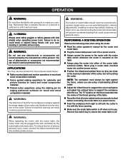
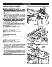
...Inch FEDEIDRECTION LOOSEN 0 1/4 FENCE LOCK KNOBS TIGHTEN SCALE CUTTER PROPER DISTANCE DIFREEECDTION 3 2 3 1 2 0 1 Inch SCALE Fig. 22 18 ADJUSTING DEPTH OF CUT We recommend that cuts be careful not to the desired angle. Tighten the miter gauge knob. OPERATION INSERTING/REMOVING CUTTERS Unplug the router table and/or the router. Remove the router/insert plate assembly. (See Installing Router/Insert Plate Assembly in the Assembly section.) WARNING: 3 2 1 0 1 Inch If you are changing a cutter immediately after use a wrench. NOTE: The outfeed fence...
...Inch FEDEIDRECTION LOOSEN 0 1/4 FENCE LOCK KNOBS TIGHTEN SCALE CUTTER PROPER DISTANCE DIFREEECDTION 3 2 3 1 2 0 1 Inch SCALE Fig. 22 18 ADJUSTING DEPTH OF CUT We recommend that cuts be careful not to the desired angle. Tighten the miter gauge knob. OPERATION INSERTING/REMOVING CUTTERS Unplug the router table and/or the router. Remove the router/insert plate assembly. (See Installing Router/Insert Plate Assembly in the Assembly section.) WARNING: 3 2 1 0 1 Inch If you are changing a cutter immediately after use a wrench. NOTE: The outfeed fence...

English Manual
Page 19
... types of materials. GENERAL MAINTENANCE Avoid using compressed air. 19 However, if you do not recommend using this product for extended work with any of these types of commercial solvents and may be damaged by their use only identical replacement parts. MAINTENANCE WARNING: When servicing, use . WARNING: Do not at any other parts may result in contact with side shields during power tool operation or when blowing dust...
... types of materials. GENERAL MAINTENANCE Avoid using compressed air. 19 However, if you do not recommend using this product for extended work with any of these types of commercial solvents and may be damaged by their use only identical replacement parts. MAINTENANCE WARNING: When servicing, use . WARNING: Do not at any other parts may result in contact with side shields during power tool operation or when blowing dust...

English Manual
Page 20
... a registered trademark of Ryobi Limited used under license. OPERATOR'S MANUAL ROUTER TABLE A25RT02 WARNING: Some dust created by power sanding, sawing, grinding, drilling, and other construction activities contains chemicals known to cause cancer, birth defects or other masonry products, and • arsenic and chromium from these exposures varies, depending on how often you do this type of work with approved safety equipment, such as those...
... a registered trademark of Ryobi Limited used under license. OPERATOR'S MANUAL ROUTER TABLE A25RT02 WARNING: Some dust created by power sanding, sawing, grinding, drilling, and other construction activities contains chemicals known to cause cancer, birth defects or other masonry products, and • arsenic and chromium from these exposures varies, depending on how often you do this type of work with approved safety equipment, such as those...
Repair Sheet
Page 3
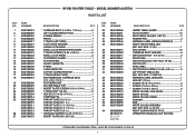
...9002780012 9002780013 26 9002780054 27 9002780072 RYOBI ROUTER TABLE - MODEL NUMBER A25RT02 PARTS LIST DESCRIPTION QTY * CARRIAGE BOLT (1/4-20 x 1 3/4 in 6 LEFT SLIDING FENCE FACE 1 JOINING FENCE 1 FENCE 1 T-TRACK (LEFT SIDE 1 LOCK KNOB WASHER 7 LARGE LOCK KNOB 2 SMALL LOCK KNOB W/SHOULDER 5 T-TRACK SCREW (10-24 x 5/8 in 3 LEFT FRONT TABLE LEG (INC. KEY NOS. 39-40 1 SWITCH KEY 1 DATA LABEL 1 * SWITCH BOX SCREW (1/4-20 x 5/8 in 8 SMALL LOCK KNOB 2 CUTTER/BIT GUARD 1 FLAT WASHER 4 SHORT HINGE PIN 1 E-RING 4 LONG HINGE PIN 1 CUTTER GUARD BRACKET 1 T-TRACK (RIGHT SIDE...
...9002780012 9002780013 26 9002780054 27 9002780072 RYOBI ROUTER TABLE - MODEL NUMBER A25RT02 PARTS LIST DESCRIPTION QTY * CARRIAGE BOLT (1/4-20 x 1 3/4 in 6 LEFT SLIDING FENCE FACE 1 JOINING FENCE 1 FENCE 1 T-TRACK (LEFT SIDE 1 LOCK KNOB WASHER 7 LARGE LOCK KNOB 2 SMALL LOCK KNOB W/SHOULDER 5 T-TRACK SCREW (10-24 x 5/8 in 3 LEFT FRONT TABLE LEG (INC. KEY NOS. 39-40 1 SWITCH KEY 1 DATA LABEL 1 * SWITCH BOX SCREW (1/4-20 x 5/8 in 8 SMALL LOCK KNOB 2 CUTTER/BIT GUARD 1 FLAT WASHER 4 SHORT HINGE PIN 1 E-RING 4 LONG HINGE PIN 1 CUTTER GUARD BRACKET 1 T-TRACK (RIGHT SIDE...


