Owners Manual
Page 4
...cut material when blade is equipped with or without yellow stripes is properly grounded. Use only correct electrical devices: 3-wire extension cords that have the proper outlet installed by an authorized service center. USE ONLY CORRECT BLADES. The conductor with insulation ...accident causing possible serious personal injury. ALWAYS USE BLADE GUARD, Spreader, AND ANTIKICKBACK PAWLS on all fences and auxiliary tables before connecting to whether the tool is the equipment-grounding conductor. Size and shape can result in place over the blade while...
...cut material when blade is equipped with or without yellow stripes is properly grounded. Use only correct electrical devices: 3-wire extension cords that have the proper outlet installed by an authorized service center. USE ONLY CORRECT BLADES. The conductor with insulation ...accident causing possible serious personal injury. ALWAYS USE BLADE GUARD, Spreader, AND ANTIKICKBACK PAWLS on all fences and auxiliary tables before connecting to whether the tool is the equipment-grounding conductor. Size and shape can result in place over the blade while...
Owners Manual
Page 11
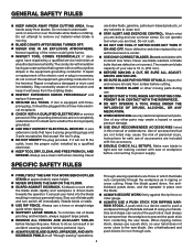
RIP FENCE MITER GAUGE GROOVE RIP FENCE SCALE TABLE EXTENSION MITER gauge RIP FENCE STORAGE BRACKETS FRONT bevel RAIL ADJUSTING 45 HANDWHEEL BEVEL SCALE LOCKING HANDLE SWITCH ASSEMBLY hEight ADJUSTING HANDWHEEL HEIGHT LOCK KNOB bevel ...
RIP FENCE MITER GAUGE GROOVE RIP FENCE SCALE TABLE EXTENSION MITER gauge RIP FENCE STORAGE BRACKETS FRONT bevel RAIL ADJUSTING 45 HANDWHEEL BEVEL SCALE LOCKING HANDLE SWITCH ASSEMBLY hEight ADJUSTING HANDWHEEL HEIGHT LOCK KNOB bevel ...
Owners Manual
Page 12
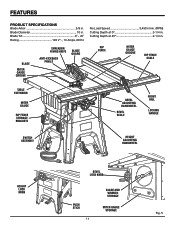
...is thrown back toward the operator, the teeth dig into the wood to heed this operator's manual as well as a knowledge of kickback. TABLE EXTENSION - HEIGHT ADJUSTING HANDWHEEL/ HEIGHT LOCK KNOB - Failure to help prevent or reduce the possibility of the project you are attempting. A removable ... gauge aligns the wood for use blades rated less than the saw has an easy access power switch located below the saw table, the table extensions give the operator additional support when cutting wide workpieces. SWITCH ASSEMBLY - The height lock knob locks the height setting of the...
...is thrown back toward the operator, the teeth dig into the wood to heed this operator's manual as well as a knowledge of kickback. TABLE EXTENSION - HEIGHT ADJUSTING HANDWHEEL/ HEIGHT LOCK KNOB - Failure to help prevent or reduce the possibility of the project you are attempting. A removable ... gauge aligns the wood for use blades rated less than the saw has an easy access power switch located below the saw table, the table extensions give the operator additional support when cutting wide workpieces. SWITCH ASSEMBLY - The height lock knob locks the height setting of the...
Owners Manual
Page 15
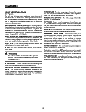
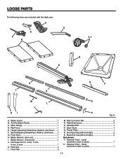
..., open end 1 I. Fastener Pack - Large (contents noted on pack 1 15 Height Adjusting Handwheel, Washer, and Knob...... 1 F. Front Rail 2 M. Spreader Bar 1 P. Small (contents noted on pack 1 S. Table Extensions 2 O. Front End Cap (left and right 2 Not shown: T. Rear Rail 2 L. Blade Wrench, closed end 1 J. LOOSE PARTS The following items are included with the...
..., open end 1 I. Fastener Pack - Large (contents noted on pack 1 15 Height Adjusting Handwheel, Washer, and Knob...... 1 F. Front Rail 2 M. Spreader Bar 1 P. Small (contents noted on pack 1 S. Table Extensions 2 O. Front End Cap (left and right 2 Not shown: T. Rear Rail 2 L. Blade Wrench, closed end 1 J. LOOSE PARTS The following items are included with the...
Owners Manual
Page 18
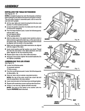
... parts: 6 Bolts (M10 x 25) 6 Lock washers (M10) 6 Flat washers (M10) With the table saw in the upside down position, place a table extension against the table top, on the other table extension. Using an 8 mm socket, tighten the socket head bolts. NOTE: The top of the outer corner has... outside a leg stand section. BOARDS flat washer lOCK washer TABLE EXTENSION LEG STAND SECTION outer cORNER 18 saw TABLE Fig. 10 TABLE EXTENSION saw table and motor housing from the box and position it upright. Lift the saw TABLE BOLT Fig. 11 BOLT Fig. 12 NOTE: The front ...
... parts: 6 Bolts (M10 x 25) 6 Lock washers (M10) 6 Flat washers (M10) With the table saw in the upside down position, place a table extension against the table top, on the other table extension. Using an 8 mm socket, tighten the socket head bolts. NOTE: The top of the outer corner has... outside a leg stand section. BOARDS flat washer lOCK washer TABLE EXTENSION LEG STAND SECTION outer cORNER 18 saw TABLE Fig. 10 TABLE EXTENSION saw table and motor housing from the box and position it upright. Lift the saw TABLE BOLT Fig. 11 BOLT Fig. 12 NOTE: The front ...
Owners Manual
Page 24
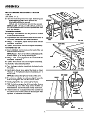
... the rear rail with and insert the bolts into the holes on the back of the saw table and table extensions. The mark on the right side indicator should be an equal gap between the saw table and the bottom of the rip fence from the front to raise the blade. Gently place... To install the rear rail: Insert eight bolts into the holes on the front of the saw table and table extensions. Using a 13 mm wrench, tighten the four center nuts. To check the table and rail position: Turn the height adjusting handwheel clockwise to back of the rip fence, on both...
... the rear rail with and insert the bolts into the holes on the back of the saw table and table extensions. The mark on the right side indicator should be an equal gap between the saw table and the bottom of the rip fence from the front to raise the blade. Gently place... To install the rear rail: Insert eight bolts into the holes on the front of the saw table and table extensions. Using a 13 mm wrench, tighten the four center nuts. To check the table and rail position: Turn the height adjusting handwheel clockwise to back of the rip fence, on both...
Owners Manual
Page 25
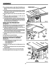
... assembled parts are flush and level. If the table extensions, rip fence, and rails are not level, make sure the table extensions are level with the top. If the table extensions and rails are level and flush with the table top. framing square HEX HEAD BOLT HEX HEAD BOLT lock washer...) Slide two hex head bolts into the groove on each of the table top as shown to make sure all bolts. Thread two hex nuts over each rail. Check the table and extensions to make adjustments by slightly loosening and retightening the bolts and nuts, and repositioning ...
... assembled parts are flush and level. If the table extensions, rip fence, and rails are not level, make sure the table extensions are level with the top. If the table extensions and rails are level and flush with the table top. framing square HEX HEAD BOLT HEX HEAD BOLT lock washer...) Slide two hex head bolts into the groove on each of the table top as shown to make sure all bolts. Thread two hex nuts over each rail. Check the table and extensions to make adjustments by slightly loosening and retightening the bolts and nuts, and repositioning ...
Owners Manual
Page 44
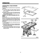
... shown. 14-5/8 in. 3/4 in. 1 in. Attach the extension to the saw with the saw table and extensions. You may construct a wood table extension to the spreader bar. Insert the table extension from underneath the rails and set it is aligned with the rest of the saw table. TO INSTALL THE TABLE EXTENSION ONTO THE RAILS See Figure 69. in...
... shown. 14-5/8 in. 3/4 in. 1 in. Attach the extension to the saw with the saw table and extensions. You may construct a wood table extension to the spreader bar. Insert the table extension from underneath the rails and set it is aligned with the rest of the saw table. TO INSTALL THE TABLE EXTENSION ONTO THE RAILS See Figure 69. in...

Owners Manual
Page 46
... 46 BEVEL HANDLE Fig. 74 The adjustment screws must be checked. Unplug the saw. Raise the blade. Remove the blade guard. After extensive use, it may need to zero. NOTE: Make sure that the square contacts the flat part of the saw blade, not the blade teeth. ... the flat part of the saw blade, not the blade teeth. Place a combination square beside the blade on the left side of your saw table surface so the workpiece doesn't catch on the left. If the blade is not an exact 45°, loosen the adjustment bolt and the bevel...
... 46 BEVEL HANDLE Fig. 74 The adjustment screws must be checked. Unplug the saw. Raise the blade. Remove the blade guard. After extensive use, it may need to zero. NOTE: Make sure that the square contacts the flat part of the saw blade, not the blade teeth. ... the flat part of the saw blade, not the blade teeth. Place a combination square beside the blade on the left side of your saw table surface so the workpiece doesn't catch on the left. If the blade is not an exact 45°, loosen the adjustment bolt and the bevel...


