

Operation Manual
Page 2
... this product making its use more pleasant and enjoyable. English TABLE OF CONTENTS Introduction...2 General Safety Rules...3-4 Specific Safety Rules...5 Symbols...6 Electrical...7-8 Features...9-10 Tools Needed...10 Loose Parts...11 Assembly...12-17 Operation...18-21 Adjustments...22-23 Maintenance...24-25 Warranty...26 Parts Ordering and Service...Back page INTRODUCTION This...
... this product making its use more pleasant and enjoyable. English TABLE OF CONTENTS Introduction...2 General Safety Rules...3-4 Specific Safety Rules...5 Symbols...6 Electrical...7-8 Features...9-10 Tools Needed...10 Loose Parts...11 Assembly...12-17 Operation...18-21 Adjustments...22-23 Maintenance...24-25 Warranty...26 Parts Ordering and Service...Back page INTRODUCTION This...

Operation Manual
Page 3
... the tool, a guard or other part that is damaged should wear safety glasses and be carefully checked to operate the tool. DON'T OVERREACH. Use clamps or a vise to carry the current your hand and frees both hands to determine that keys and adjusting wrenches are rated for recommended accessories. These cords are removed from heat, oil, and sharp edges. ALWAYS USE AN OUTDOOR EXTENSION CORD MARKED "W-A" OR "W". A wire gauge size (A.W.G.) of electric shock...
... the tool, a guard or other part that is damaged should wear safety glasses and be carefully checked to operate the tool. DON'T OVERREACH. Use clamps or a vise to carry the current your hand and frees both hands to determine that keys and adjusting wrenches are rated for recommended accessories. These cords are removed from heat, oil, and sharp edges. ALWAYS USE AN OUTDOOR EXTENSION CORD MARKED "W-A" OR "W". A wire gauge size (A.W.G.) of electric shock...

Operation Manual
Page 4
... to remove cut material when wheel is 7 in this manual or addendums. Use of the motor could ignite fumes. INSPECT TOOL CORDS PERIODICALLY. Do not attempt to whether the tool is equipped with incorrect size holes. If it well away from wheels. Have defective switches replaced by an authorized service center. USE ONLY CORRECT WHEELS. If tool is properly grounded. USE ONLY CORRECT ELECTRICAL DEVICES: 3-wire extension cords...
... to remove cut material when wheel is 7 in this manual or addendums. Use of the motor could ignite fumes. INSPECT TOOL CORDS PERIODICALLY. Do not attempt to whether the tool is equipped with incorrect size holes. If it well away from wheels. Have defective switches replaced by an authorized service center. USE ONLY CORRECT WHEELS. If tool is properly grounded. USE ONLY CORRECT ELECTRICAL DEVICES: 3-wire extension cords...
Operation Manual
Page 5
... exposure, work using the saw before operating. e) Replace damaged cutting wheel before servicing, when changing cutting wheels, and cleaning. If you do this tool, loan them frequently and use to instruct other reproductive harm. SPECIFIC SAFETY RULES SECURE WORK firmly against the miter guide or fence. NEVER stand or have any work in line with the path of the wheel. NEVER attempt to free a stalled wheel without first turning the saw OFF and...
... exposure, work using the saw before operating. e) Replace damaged cutting wheel before servicing, when changing cutting wheels, and cleaning. If you do this tool, loan them frequently and use to instruct other reproductive harm. SPECIFIC SAFETY RULES SECURE WORK firmly against the miter guide or fence. NEVER stand or have any work in line with the path of the wheel. NEVER attempt to free a stalled wheel without first turning the saw OFF and...
Operation Manual
Page 7
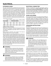
... of power and causing the motor to overheat. Do not use an extension cord that accept the tool's plug. An undersized extension cord will draw. NOTE: AWG = American Wire Gauge Always use an adapter with a damaged cord since touching the damaged area could cause electrical shock resulting in GFCI protection and may not be used . **Ampere rating (on tool data plate) 0-2.0 2.1-3.4 3.5-5.0 5.1-7.0 7.1-12.0 12.1-16.0 Cord Length Wire Size...
... of power and causing the motor to overheat. Do not use an extension cord that accept the tool's plug. An undersized extension cord will draw. NOTE: AWG = American Wire Gauge Always use an adapter with a damaged cord since touching the damaged area could cause electrical shock resulting in GFCI protection and may not be used . **Ampere rating (on tool data plate) 0-2.0 2.1-3.4 3.5-5.0 5.1-7.0 7.1-12.0 12.1-16.0 Cord Length Wire Size...

Operation Manual
Page 10
.... TOOLS NEEDED The following tools (not included or drawn to the cutting wheel. ON/OFF SWITCH - SLIDING TABLE - tile cutting wheel is included with all operating features and safety rules. 7 in . Protects user from wheel contact on upper portion of this product requires an understanding of the information on the miter guide shows the exact angle for assembly and alignment: PHILLIPS SCREWDRIVER FLATHEAD SCREWDRIVER 10 mm, 14 mm WRENCH C-CLAMP FRAMING SQUARE 10...
.... TOOLS NEEDED The following tools (not included or drawn to the cutting wheel. ON/OFF SWITCH - SLIDING TABLE - tile cutting wheel is included with all operating features and safety rules. 7 in . Protects user from wheel contact on upper portion of this product requires an understanding of the information on the miter guide shows the exact angle for assembly and alignment: PHILLIPS SCREWDRIVER FLATHEAD SCREWDRIVER 10 mm, 14 mm WRENCH C-CLAMP FRAMING SQUARE 10...

Operation Manual
Page 11
Water tray 1 M- Socket Head Screw 5 11 - Arbor wrench 1 E - Water pump 1 L - English Miter guide 1 N - Hex nut 5 O - Arbor nut 1 G - Cutting wheel 1 Fig. 5 I G F J 45 M K MAX L MIN A - Inner washer 1 J - 90° fitting 2 K - Sliding table 1 C - Water tray frame 1 D - LOOSE PARTS The following items are included with your tile saw: A B C N O P D HE I - Spacer 5 P - Wheel wrench 1 F - Motor head assembly 1 B - Outer washer 1 H -
Water tray 1 M- Socket Head Screw 5 11 - Arbor wrench 1 E - Water pump 1 L - English Miter guide 1 N - Hex nut 5 O - Arbor nut 1 G - Cutting wheel 1 Fig. 5 I G F J 45 M K MAX L MIN A - Inner washer 1 J - 90° fitting 2 K - Sliding table 1 C - Water tray frame 1 D - LOOSE PARTS The following items are included with your tile saw: A B C N O P D HE I - Spacer 5 P - Wheel wrench 1 F - Motor head assembly 1 B - Outer washer 1 H -
Operation Manual
Page 12
.... Inspect the tool carefully to make sure no load speed of a product that you unpack it , check for use wheel with this list are not assembled to comply could result in this tool. WARNING: Do not use this tool or create accessories not recommended for accuracy. WARNING: Do not use the 7 in personal injury. Finger tighten then lightly torque using hex nuts. English SOCKET HEAD SCREW Fig. 6 NOTE...
.... Inspect the tool carefully to make sure no load speed of a product that you unpack it , check for use wheel with this list are not assembled to comply could result in this tool. WARNING: Do not use this tool or create accessories not recommended for accuracy. WARNING: Do not use the 7 in personal injury. Finger tighten then lightly torque using hex nuts. English SOCKET HEAD SCREW Fig. 6 NOTE...
Operation Manual
Page 14
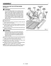
... wheel wrench on wheel going in contact with the flats on the arbor. English ASSEMBLY INSTALLING THE TILE CUTTING WHEEL See Figure 11. WARNING: A 7 in each nozzle should face the cutting wheel. WARNING: Always install the inner wheel washer before placing wheel on the spindle. Never use a wheel that have openings, grooves, or teeth on this tool. Place the cutting wheel onto arbor with the flats on the arbor. Replace the arbor nut...
... wheel wrench on wheel going in contact with the flats on the arbor. English ASSEMBLY INSTALLING THE TILE CUTTING WHEEL See Figure 11. WARNING: A 7 in each nozzle should face the cutting wheel. WARNING: Always install the inner wheel washer before placing wheel on the spindle. Never use a wheel that have openings, grooves, or teeth on this tool. Place the cutting wheel onto arbor with the flats on the arbor. Replace the arbor nut...

Operation Manual
Page 15
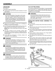
...-14. ASSEMBLY INSTALLING THE MITER GUIDE See Figure 12. The miter guide can be used from the tray to the cutting wheel. The pump is equipped with the hose end of the fitting facing the rear of the miter guide on the sliding table fence. Lock the miter guide securely to the table by moving the guide left or right. Tighten the knob securely before turning on the electrical cord and plug...
...-14. ASSEMBLY INSTALLING THE MITER GUIDE See Figure 12. The miter guide can be used from the tray to the cutting wheel. The pump is equipped with the hose end of the fitting facing the rear of the miter guide on the sliding table fence. Lock the miter guide securely to the table by moving the guide left or right. Tighten the knob securely before turning on the electrical cord and plug...

Operation Manual
Page 17
... tool, wait for the wheel to stop moving and disconnect the power to the tool before operating the tool. • Do not expose to polarity indicators inside the battery compartment. Replace the battery compartment cover. COMPLIES WITH 21 CFR PARTS 1040.10 AND 1040.11 RYLD 640-670 LASER GUIDE SWITCH Fig. 18 AVOID EXPOSURE: Laser radiation is turned on it can be used. Reinstall screw and tighten...
... tool, wait for the wheel to stop moving and disconnect the power to the tool before operating the tool. • Do not expose to polarity indicators inside the battery compartment. Replace the battery compartment cover. COMPLIES WITH 21 CFR PARTS 1040.10 AND 1040.11 RYLD 640-670 LASER GUIDE SWITCH Fig. 18 AVOID EXPOSURE: Laser radiation is turned on it can be used. Reinstall screw and tighten...
Operation Manual
Page 18
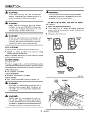
... tool for the purposes listed below: Straight line cutting operations such as cross cutting, mitering, ripping, and beveling NOTE: This saw turned OFF, remove the switch key. Failure to be kicked back toward the operator and result in objects being thrown into the power source. To turn OFF. To unlock and raise the motor head: Firmly grasp the "D" handle and apply downward pressure while at the same time turning...
... tool for the purposes listed below: Straight line cutting operations such as cross cutting, mitering, ripping, and beveling NOTE: This saw turned OFF, remove the switch key. Failure to be kicked back toward the operator and result in objects being thrown into the power source. To turn OFF. To unlock and raise the motor head: Firmly grasp the "D" handle and apply downward pressure while at the same time turning...

Operation Manual
Page 19
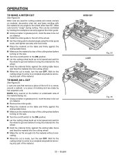
... motor head: Firmly grasp the "D" handle and apply downward pressure while at the same time turning the lock knob clockwise to get wet before moving the material into the wheel. Hold the material firmly against the sliding table fence and feed the material into the cutting wheel. When the cut is made , turn the saw OFF. Debris from the marked line. CROSS CUT SLIDING TABLE FENCE MITER GUIDE DIAGONAL CUT...
... motor head: Firmly grasp the "D" handle and apply downward pressure while at the same time turning the lock knob clockwise to get wet before moving the material into the wheel. Hold the material firmly against the sliding table fence and feed the material into the cutting wheel. When the cut is made , turn the saw OFF. Debris from the marked line. CROSS CUT SLIDING TABLE FENCE MITER GUIDE DIAGONAL CUT...
Operation Manual
Page 20
... material. Install the miter guide to the left of the wheel. Set the miter guide to desired angle using the miter guide scale, and tighten securely with the material at any angle to get wet before removing any part of the material. Miter cuts tend to get wet before removing any part of the cutting wheel before turning on the saw OFF. Wait for the cutting wheel to come to a complete stop before moving...
... material. Install the miter guide to the left of the wheel. Set the miter guide to desired angle using the miter guide scale, and tighten securely with the material at any angle to get wet before removing any part of the material. Miter cuts tend to get wet before removing any part of the cutting wheel before turning on the saw OFF. Wait for the cutting wheel to come to a complete stop before moving...

Operation Manual
Page 21
... before tilting the saw head. Loosen the bevel knob and tilt the motor head. Turn the on /off switch to get wet before moving the material into the wheel. Hold the material firmly against the sliding table fence and feed the material into the wheel. Hold the motor head firmly by positioning the material directly underneath the cutting wheel and lowering the wheel onto the...
... before tilting the saw head. Loosen the bevel knob and tilt the motor head. Turn the on /off switch to get wet before moving the material into the wheel. Hold the material firmly against the sliding table fence and feed the material into the wheel. Hold the motor head firmly by positioning the material directly underneath the cutting wheel and lowering the wheel onto the...
Operation Manual
Page 22
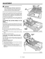
... for making very accurate cuts. TO SQUARE THE CUTTING WHEEL TO THE TABLE See Figure 28. Do not start any adjustments until the fence is visibly off track adjustments may be required. ADJUSTMENT WARNING: Before performing any adjustment, make sure the tool is unplugged from the power supply and the switch is loose: Loosen the cam bolt nut. Insert hex key through the hole in...
... for making very accurate cuts. TO SQUARE THE CUTTING WHEEL TO THE TABLE See Figure 28. Do not start any adjustments until the fence is visibly off track adjustments may be required. ADJUSTMENT WARNING: Before performing any adjustment, make sure the tool is unplugged from the power supply and the switch is loose: Loosen the cam bolt nut. Insert hex key through the hole in...

Operation Manual
Page 23
... before raising the wheel. Raise the motor head. Unplug the saw. Turn on the saw blade to secure a piece of scrap tile. Plug the saw into the power source and make practice cuts on the saw . NOTE: Avoid direct eye exposure when using the laser guide. Use the work clamp or a C-clamp to stop rotating before cutting through your workpiece. 45° BEVEL LOCK KNOB 0° SCREW 0 COMBINATION SQUARE 45 Fig. 30...
... before raising the wheel. Raise the motor head. Unplug the saw. Turn on the saw blade to secure a piece of scrap tile. Plug the saw into the power source and make practice cuts on the saw . NOTE: Avoid direct eye exposure when using the laser guide. Use the work clamp or a C-clamp to stop rotating before cutting through your workpiece. 45° BEVEL LOCK KNOB 0° SCREW 0 COMBINATION SQUARE 45 Fig. 30...
Operation Manual
Page 24
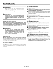
...operating conditions. WARNING: Always wear eye protection with side shields marked to a power source. 24 - CLEANING THE RAILS During use only identical replacement parts. CLEANING THE SAW Unplug the saw. Using a small brush and/or water, clean each piece thoroughly removing any debris or trash that the water hose...Replace the front cover. If operation is important to remove dirt, dust, oil, grease, etc. Do not allow the water to damage from sliding smoothly. MAINTENANCE WARNING: When servicing, use , the rails will slide smoothly. It is dusty, also wear a dust...
...operating conditions. WARNING: Always wear eye protection with side shields marked to a power source. 24 - CLEANING THE RAILS During use only identical replacement parts. CLEANING THE SAW Unplug the saw. Using a small brush and/or water, clean each piece thoroughly removing any debris or trash that the water hose...Replace the front cover. If operation is important to remove dirt, dust, oil, grease, etc. Do not allow the water to damage from sliding smoothly. MAINTENANCE WARNING: When servicing, use , the rails will slide smoothly. It is dusty, also wear a dust...

Operation Manual
Page 25
... with a screwdriver. Make sure curvature of brush matches curvature of carbon remaining. The nozzles just push on and pull off the connector on either has less than 1/4 in brush tube. Make sure brush cap is spring loaded and will pop out when you remove brush cap. Remove brush assembly. Check for wear. Brush assembly is oriented correctly (straight) and replace. Tighten brush cap...
... with a screwdriver. Make sure curvature of brush matches curvature of carbon remaining. The nozzles just push on and pull off the connector on either has less than 1/4 in brush tube. Make sure brush cap is spring loaded and will pop out when you remove brush cap. Remove brush assembly. Check for wear. Brush assembly is oriented correctly (straight) and replace. Tighten brush cap...
Operation Manual
Page 26
... packaged with the tool such as brushes, chucks, motors, switches, cords, gears and even cordless batteries in to state. WHAT IS NOT COVERED This warranty applies only to the dealer from which vary from RIDGID®, Inc. AND ONE WORLD TECHNOLOGIES, INC. All warranty communications should be directed to One World Technologies, Inc., attn: RIDGID® Hand Held and Stationary Power Tool Technical Service at www.ridgid.com. freight...
... packaged with the tool such as brushes, chucks, motors, switches, cords, gears and even cordless batteries in to state. WHAT IS NOT COVERED This warranty applies only to the dealer from which vary from RIDGID®, Inc. AND ONE WORLD TECHNOLOGIES, INC. All warranty communications should be directed to One World Technologies, Inc., attn: RIDGID® Hand Held and Stationary Power Tool Technical Service at www.ridgid.com. freight...


