
User Manual
Page 1
Write the serial number in this manual before using this manual for reference. CALL TOLL-FREE: 1-888-936-4266 Mon.-Fri., 7:30 until 16:30 ET (excluding holidays) OR E-MAIL US: [email protected] USER'S MANUAL CAUTION Read all precautions and instructions in the space above for future reference. Serial Number Decal QUESTIONS? RBCCEL4255.0 Serial No. Keep this equipment. www.reebokfitness.com Model No. If you have questions, or if parts are damaged or missing, PLEASE CONTACT OUR CUSTOMER SERVICE DEPARTMENT DIRECTLY.
Write the serial number in this manual before using this manual for reference. CALL TOLL-FREE: 1-888-936-4266 Mon.-Fri., 7:30 until 16:30 ET (excluding holidays) OR E-MAIL US: [email protected] USER'S MANUAL CAUTION Read all precautions and instructions in the space above for future reference. Serial Number Decal QUESTIONS? RBCCEL4255.0 Serial No. Keep this equipment. www.reebokfitness.com Model No. If you have questions, or if parts are damaged or missing, PLEASE CONTACT OUR CUSTOMER SERVICE DEPARTMENT DIRECTLY.
User Manual
Page 2
... a free replacement decal. Apply the decal in the location shown. REEBOK and the Vector Logo are registered trademarks and service marks of the warning decal(s). TABLE OF CONTENTS WARNING DECAL PLACEMENT 2 IMPORTANT PRECAUTIONS 3 BEFORE YOU BEGIN 4 ASSEMBLY 5 HOW TO USE THE CHEST PULSE SENSOR 12 HOW TO USE THE ELLIPTICAL 14 MAINTENANCE AND TROUBLESHOOTING 21 EXERCISE GUIDELINES 22 PART LIST 24 EXPLODED DRAWING 25 ORDERING REPLACEMENT PARTS Back Cover LIMITED WARRANTY Back Cover...
... a free replacement decal. Apply the decal in the location shown. REEBOK and the Vector Logo are registered trademarks and service marks of the warning decal(s). TABLE OF CONTENTS WARNING DECAL PLACEMENT 2 IMPORTANT PRECAUTIONS 3 BEFORE YOU BEGIN 4 ASSEMBLY 5 HOW TO USE THE CHEST PULSE SENSOR 12 HOW TO USE THE ELLIPTICAL 14 MAINTENANCE AND TROUBLESHOOTING 21 EXERCISE GUIDELINES 22 PART LIST 24 EXPLODED DRAWING 25 ORDERING REPLACEMENT PARTS Back Cover LIMITED WARRANTY Back Cover...
User Manual
Page 3
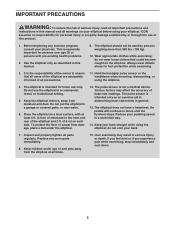
... the front and rear of the elliptical and 2 ft. (0.6 m) on each side. The pulse sensor is the responsibility of the owner to move until the flywheel stops. Keep your pedaling speed in a controlled way. 14. Keep children under age 12 and pets away from damage, place a mat under the elliptical. 12. Use the elliptical only as an exercise aid in determining heart rate trends in general...
... the front and rear of the elliptical and 2 ft. (0.6 m) on each side. The pulse sensor is the responsibility of the owner to move until the flywheel stops. Keep your pedaling speed in a controlled way. 14. Keep children under age 12 and pets away from damage, place a mat under the elliptical. 12. Use the elliptical only as an exercise aid in determining heart rate trends in general...
User Manual
Page 4
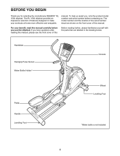
... workouts at home more effective and enjoyable. manual. If you for selecting the revolutionary REEBOK® RL 1500 elliptical. BEFORE YOU BEGIN Thank you have questions after reading this manual, please see the front cover of this Before reading further, please familiarize yourself with the parts that are shown on the front cover of this manual carefully before you , note the product model number...
... workouts at home more effective and enjoyable. manual. If you for selecting the revolutionary REEBOK® RL 1500 elliptical. BEFORE YOU BEGIN Thank you have questions after reading this manual, please see the front cover of this Before reading further, please familiarize yourself with the parts that are shown on the front cover of this manual carefully before you , note the product model number...
User Manual
Page 5
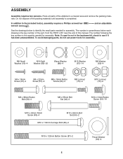
... preassembled. To avoid damaging parts, do not use power tools for assembly. Do not dispose of the packing materials until assembly is the key number of the part, from the PART LIST near the end of the elliptical in parentheses below to identify the small parts needed for assembly. The number in a cleared area and remove the packing materials. The number following the key number is not in the...
... preassembled. To avoid damaging parts, do not use power tools for assembly. Do not dispose of the packing materials until assembly is the key number of the part, from the PART LIST near the end of the elliptical in parentheses below to identify the small parts needed for assembly. The number in a cleared area and remove the packing materials. The number following the key number is not in the...
User Manual
Page 6
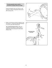
Attach the Upright (2) to the Frame (1) with two M10 x 116mm Carriage Bolts (38) and two M10 Locknuts (70). 38 8 2. While a second person hold the Upright (2) near the Frame (1), connect the Upper Wire Harness (77) to the Frame (1) with four M10 x 25mm Patch Screws (48) and four M10 Split Washers (85). 2 2 Avoid pinching the wires 85 48 85 1 70 77 78 48 85 1 6 To make assembly easier, read the 1 information on page 5 before you begin. 1. Tip: Avoid pinching the wires. Attach the Stabilizer (8) to the Lower Wire Harness (78).
Attach the Upright (2) to the Frame (1) with two M10 x 116mm Carriage Bolts (38) and two M10 Locknuts (70). 38 8 2. While a second person hold the Upright (2) near the Frame (1), connect the Upper Wire Harness (77) to the Frame (1) with four M10 x 25mm Patch Screws (48) and four M10 Split Washers (85). 2 2 Avoid pinching the wires 85 48 85 1 70 77 78 48 85 1 6 To make assembly easier, read the 1 information on page 5 before you begin. 1. Tip: Avoid pinching the wires. Attach the Stabilizer (8) to the Lower Wire Harness (78).
User Manual
Page 7
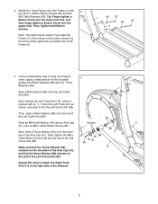
... you attach the Track Frame (4). 1 85 87 85 87 4 4. Then, tighten the M8 x 19mm Button Screw (56) into the upper hole. 3. Orient the Left Track Arm as shown, and slide it onto the Left Crank Arm (83). Attach the Track Frame (4) to keep your fingers clean, apply a small amount of the elliptical. 7 Tip: Finger tighten a Button Screw into the lower hole first, and then finger tighten a Button Screw into...
... you attach the Track Frame (4). 1 85 87 85 87 4 4. Then, tighten the M8 x 19mm Button Screw (56) into the upper hole. 3. Orient the Left Track Arm as shown, and slide it onto the Left Crank Arm (83). Attach the Track Frame (4) to keep your fingers clean, apply a small amount of the elliptical. 7 Tip: Finger tighten a Button Screw into the lower hole first, and then finger tighten a Button Screw into...
User Manual
Page 10
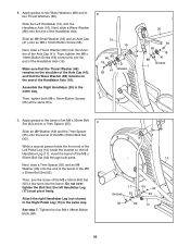
..., tighten the M8 x 19mm Button Screw (56) a few turns into the end of the Left Pedal Leg (14) inside the bracket on the end of the Axle Cap (41). Then, turn the screw of the M8 x 55mm Bolt Set (92) a few turns into the barrel. While a second person holds the front end of the Handlebar Axle (16). See step 7. Slide the Left... that the Thrust Washer (66) remains on the shoulder of the Axle Cap (41), and that the Wave Washer (88) remains on the left Handlebar Leg (17) must pivot freely. 8. Assemble the Right Handlebar (20) in the same way. Then, tighten both parts.
..., tighten the M8 x 19mm Button Screw (56) a few turns into the end of the Left Pedal Leg (14) inside the bracket on the end of the Axle Cap (41). Then, turn the screw of the M8 x 55mm Bolt Set (92) a few turns into the barrel. While a second person holds the front end of the Handlebar Axle (16). See step 7. Slide the Left... that the Thrust Washer (66) remains on the shoulder of the Axle Cap (41), and that the Wave Washer (88) remains on the left Handlebar Leg (17) must pivot freely. 8. Assemble the Right Handlebar (20) in the same way. Then, tighten both parts.
User Manual
Page 12
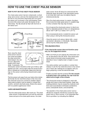
... use , the battery may be flush with people who have normal heart rhythms. Heart rate reading problems may trap moisture. • Do not expose the chest pulse sensor to direct sunlight for extended periods of time or to wet the two electrode areas on one end of the chest strap into one end of the sensor unit, as shown in a warm, dry place. Adjust...
... use , the battery may be flush with people who have normal heart rhythms. Heart rate reading problems may trap moisture. • Do not expose the chest pulse sensor to direct sunlight for extended periods of time or to wet the two electrode areas on one end of the chest strap into one end of the sensor unit, as shown in a warm, dry place. Adjust...
User Manual
Page 14
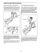
... and step onto the pedal that is recommended that you can turn the crank arms in the direction shown by the arrow; HOW TO USE THE ELLIPTICAL HOW TO MOVE AND LEVEL THE ELLIPTICAL HOW TO EXERCISE ON THE ELLIPTICAL Due to the size and weight of the elliptical, moving it . Then, step onto the other pedal. Note: The elliptical does not have a free wheel; Make sure to use your legs rather...
... and step onto the pedal that is recommended that you can turn the crank arms in the direction shown by the arrow; HOW TO USE THE ELLIPTICAL HOW TO MOVE AND LEVEL THE ELLIPTICAL HOW TO EXERCISE ON THE ELLIPTICAL Due to the size and weight of the elliptical, moving it . Then, step onto the other pedal. Note: The elliptical does not have a free wheel; Make sure to use your legs rather...
User Manual
Page 15
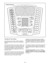
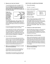
... pulse sensor or the chest pulse sensor. To use a calorie goal program, see page 16. When the manual mode of the console is reached. As you through an effective workout. The console also features two heart rate programs that automatically change the resistance of the pedals with the touch of features designed to increase or decrease your pace as it guides you exercise, the console will provide continuous exercise feedback. To use the manual mode...
... pulse sensor or the chest pulse sensor. To use a calorie goal program, see page 16. When the manual mode of the console is reached. As you through an effective workout. The console also features two heart rate programs that automatically change the resistance of the pedals with the touch of features designed to increase or decrease your pace as it guides you exercise, the console will provide continuous exercise feedback. To use the manual mode...
User Manual
Page 16
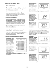
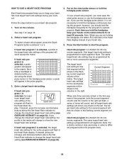
... for use the handgrip pulse sensor or the chest pulse sensor. display will show the time remaining in the program instead of the Quick Programs buttons repeatedly until the entire track is supplied by pressing any of the elapsed time. The matrix-When the manual mode or a calorie goal pro- As you have pedaled and your weight. 16 If you exercise, the indica- Note: When a program is turned on the console.
... for use the handgrip pulse sensor or the chest pulse sensor. display will show the time remaining in the program instead of the Quick Programs buttons repeatedly until the entire track is supplied by pressing any of the elapsed time. The matrix-When the manual mode or a calorie goal pro- As you have pedaled and your weight. 16 If you exercise, the indica- Note: When a program is turned on the console.
User Manual
Page 17
... plastic. For the most accurate heart rate reading, continue to start the program. See step 1 on the fans if desired. Then, press the Start button. 4. never use the chest pulse sensor, see page 12. If desired, press the Weight (WT.) increase and decrease buttons to flash, and the console will turn off . Select a calorie goal program. Change your hands. If the pedals are finished exercising, the console will pause. tic on the...
... plastic. For the most accurate heart rate reading, continue to start the program. See step 1 on the fans if desired. Then, press the Start button. 4. never use the chest pulse sensor, see page 12. If desired, press the Weight (WT.) increase and decrease buttons to flash, and the console will turn off . Select a calorie goal program. Change your hands. If the pedals are finished exercising, the console will pause. tic on the...

User Manual
Page 18
...; Press the Start button or begin pedaling to pedal at a pace that is programmed for two or more consecutive segments. Turn on page 16. 7. One resistance setting and one of the indicators on the fans if desired. When you . See step 4 on the console. Turn on the left . tance settings for you start the program. gram, the pace guide will show the new resistance settings. 5. If you change if...
...; Press the Start button or begin pedaling to pedal at a pace that is programmed for two or more consecutive segments. Turn on page 16. 7. One resistance setting and one of the indicators on the fans if desired. When you . See step 4 on the console. Turn on the left . tance settings for you start the program. gram, the pace guide will show the new resistance settings. 5. If you change if...
User Manual
Page 19
... column of your workout. The same target heart rate setting is selected, a pulse graphic will move one column to use the handgrip pulse sensor. Turn on the chest pulse sensor or hold the handgrips continuously during your heart rate. 5. If you are not holding the handgrips, the letters PLS will flash in the Heart Rate display instead of the matrix. Press the Start button to hold the handgrip pulse sensor. Each time a heartbeat...
... column of your workout. The same target heart rate setting is selected, a pulse graphic will move one column to use the handgrip pulse sensor. Turn on the chest pulse sensor or hold the handgrips continuously during your heart rate. 5. If you are not holding the handgrips, the letters PLS will flash in the Heart Rate display instead of the matrix. Press the Start button to hold the handgrip pulse sensor. Each time a heartbeat...
User Manual
Page 20
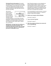
... page 17. 8. During both heart rate programs, the console will regularly compare your heart rate to the target heart rate setting. Monitor your heart rate closer to exercise at a pace that is comfortable for several seconds, a tone will sound and the program will pause. See step 6 on page 16. 7. However, when the console compares your heart rate to the target heart rate setting, the resistance of the pedals will turn off automatically. When the...
... page 17. 8. During both heart rate programs, the console will regularly compare your heart rate to the target heart rate setting. Monitor your heart rate closer to exercise at a pace that is comfortable for several seconds, a tone will sound and the program will pause. See step 6 on page 16. 7. However, when the console compares your heart rate to the target heart rate setting, the resistance of the pedals will turn off automatically. When the...
User Manual
Page 21
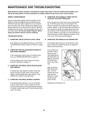
... is slipping. Remove all external parts of the drive belt. 2. If the console turns off as soon as you stop pedaling, the battery pack may be charged. Then, Flange Nut clockwise until the pedal disc stops rubbing. Never spray any cleaner directly onto the elliptical. TROUBLESHOOTING 5. If the pedals slip during use a one hundred percent cotton cloth. left Pedal Disc (5). WEEKLY MAINTENANCE Inspect and properly tighten all debris from the track and...
... is slipping. Remove all external parts of the drive belt. 2. If the console turns off as soon as you stop pedaling, the battery pack may be charged. Then, Flange Nut clockwise until the pedal disc stops rubbing. Never spray any cleaner directly onto the elliptical. TROUBLESHOOTING 5. If the pedals slip during use a one hundred percent cotton cloth. left Pedal Disc (5). WEEKLY MAINTENANCE Inspect and properly tighten all debris from the track and...
User Manual
Page 22
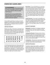
... a guide to success is near the lowest number in your body uses carbohydrate calories for successful results. The chart below shows recommended heart rates for aerobic exercise. To find the proper intensity level, find the proper intensity level. The three numbers listed above your age define your physician. For aerobic exercise, adjust the intensity of stretching and light exercise. WORKOUT GUIDELINES Warming Up-Start with...
... a guide to success is near the lowest number in your body uses carbohydrate calories for successful results. The chart below shows recommended heart rates for aerobic exercise. To find the proper intensity level, find the proper intensity level. The three numbers listed above your age define your physician. For aerobic exercise, adjust the intensity of stretching and light exercise. WORKOUT GUIDELINES Warming Up-Start with...
User Manual
Page 24
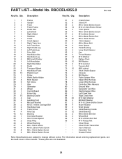
... Console M6 Washer Pulse Jumper Wire Upper Wire Harness Lower Wire Harness Controller Wire Harness Ground Wire Generator Coil Wire Electromagnet Wire Left Crank Arm Right Crank Arm M10 Split Washer M8 Split Washer M10 x 123mm Button Screw Wave Washer Weld Spacer Small Bearing Cradle Small Bearing M8 x 55mm Bolt Set Wheel Bolt M10 x 65mm Bolt Set M10 Flange Nut Chest Strap Chest Pulse Transmitter Userʼs Manual Assembly Tool Grease Packet Note: Specifications are not illustrated. 24 For information about ordering replacement parts...
... Console M6 Washer Pulse Jumper Wire Upper Wire Harness Lower Wire Harness Controller Wire Harness Ground Wire Generator Coil Wire Electromagnet Wire Left Crank Arm Right Crank Arm M10 Split Washer M8 Split Washer M10 x 123mm Button Screw Wave Washer Weld Spacer Small Bearing Cradle Small Bearing M8 x 55mm Bolt Set Wheel Bolt M10 x 65mm Bolt Set M10 Flange Nut Chest Strap Chest Pulse Transmitter Userʼs Manual Assembly Tool Grease Packet Note: Specifications are not illustrated. 24 For information about ordering replacement parts...
User Manual
Page 28
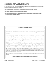
... repairs not provided by an ICON authorized service center; ICON is authorized by ICON. The warranty extended hereunder is limited to repairing or replacing, at ICONʼs option, the product through one (1) year from province to province. ICONʼs obligation under normal use and service conditions. ICON of this manual. ORDERING REPLACEMENT PARTS To order replacement parts, please see the PART LIST and the EXPLODED DRAWING near the end of this manual) LIMITED WARRANTY ICON...
... repairs not provided by an ICON authorized service center; ICON is authorized by ICON. The warranty extended hereunder is limited to repairing or replacing, at ICONʼs option, the product through one (1) year from province to province. ICONʼs obligation under normal use and service conditions. ICON of this manual. ORDERING REPLACEMENT PARTS To order replacement parts, please see the PART LIST and the EXPLODED DRAWING near the end of this manual) LIMITED WARRANTY ICON...


