
English Manual
Page 1
USER’'S MANUAL Write the serial number in this manual before using this manual for reference. Serial Number Decal ACTIVATE YOUR WARRANTY To register your product and activate your warranty today, go to www.reebokservice.com/ registration. Keep this equipment. CUSTOMER CARE For service at any time, go to www.reebokservice.com. www.reebokfitness.com Model No. RBEX05813.0 Serial No. Or call 1-877-994-4999...
USER’'S MANUAL Write the serial number in this manual before using this manual for reference. Serial Number Decal ACTIVATE YOUR WARRANTY To register your product and activate your warranty today, go to www.reebokservice.com/ registration. Keep this equipment. CUSTOMER CARE For service at any time, go to www.reebokservice.com. www.reebokfitness.com Model No. RBEX05813.0 Serial No. Or call 1-877-994-4999...
English Manual
Page 2
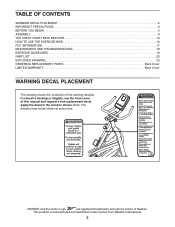
... PRECAUTIONS 3 BEFORE YOU BEGIN 5 ASSEMBLY 6 THE CHEST HEART RATE MONITOR 13 HOW TO USE THE EXERCISE BIKE 14 FCC INFORMATION 17 MAINTENANCE AND TROUBLESHOOTING 18 EXERCISE GUIDELINES 19 PART LIST 22 EXPLODED DRAWING 23 ORDERING REPLACEMENT PARTS Back Cover LIMITED WARRANTY Back Cover WARNING DECAL PLACEMENT This drawing shows the location(s) of Reebok. If a decal is manufactured and distributed under license from Reebok International. 2 Apply the decal in the location shown. This product is...
... PRECAUTIONS 3 BEFORE YOU BEGIN 5 ASSEMBLY 6 THE CHEST HEART RATE MONITOR 13 HOW TO USE THE EXERCISE BIKE 14 FCC INFORMATION 17 MAINTENANCE AND TROUBLESHOOTING 18 EXERCISE GUIDELINES 19 PART LIST 22 EXPLODED DRAWING 23 ORDERING REPLACEMENT PARTS Back Cover LIMITED WARRANTY Back Cover WARNING DECAL PLACEMENT This drawing shows the location(s) of Reebok. If a decal is manufactured and distributed under license from Reebok International. 2 Apply the decal in the location shown. This product is...
English Manual
Page 3
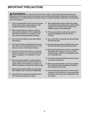
... precautions and instructions in this manual and all warnings on your exercise bike before using the exercise bike; Replace any exercise program, consult your back straight while using your back. 13. When the exercise bike is intended for foot protection. 10. Always wear athletic shoes for home use , tighten the resistance knob completely to protect the floor or carpet. Make sure that all users of the exercise bike are adequately informed of...
... precautions and instructions in this manual and all warnings on your exercise bike before using the exercise bike; Replace any exercise program, consult your back straight while using your back. 13. When the exercise bike is intended for foot protection. 10. Always wear athletic shoes for home use , tighten the resistance knob completely to protect the floor or carpet. Make sure that all users of the exercise bike are adequately informed of...
English Manual
Page 5
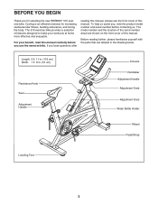
...) Resistance Knob Seat Adjustment Handle Console Handlebar Adjustment Handle Adjustment Knob Adjustment Knob Water Bottle Holder Wheel Pedal/Strap Leveling Foot 5 Length: 3 ft. 11 in. (119 cm) Width: 1 ft. 8 in the drawing below. The 510 exercise bike provides a selection of this manual. The model number and the location of this manual. To help us assist you, note the product model number and serial number before you for increasing cardiovascular fitness, building endurance, and toning the body...
...) Resistance Knob Seat Adjustment Handle Console Handlebar Adjustment Handle Adjustment Knob Adjustment Knob Water Bottle Holder Wheel Pedal/Strap Leveling Foot 5 Length: 3 ft. 11 in. (119 cm) Width: 1 ft. 8 in the drawing below. The 510 exercise bike provides a selection of this manual. The model number and the location of this manual. To help us assist you, note the product model number and serial number before you for increasing cardiovascular fitness, building endurance, and toning the body...
English Manual
Page 6
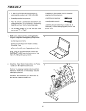
... one adjustable wrench Assembly may be easier if you ever need to contact Customer Care •• allows us to www.reebokservice.com/registration on your computer and register your product. 1 •• activates your product. 2. Attach the Rear Stabilizer (7) to assemble this product, call CUSTOMER CARE (see the front cover of this manual) and register your warranty •...
... one adjustable wrench Assembly may be easier if you ever need to contact Customer Care •• allows us to www.reebokservice.com/registration on your computer and register your product. 1 •• activates your product. 2. Attach the Rear Stabilizer (7) to assemble this product, call CUSTOMER CARE (see the front cover of this manual) and register your warranty •...

English Manual
Page 8
... turn it in the desired direction again. Slide the Seat (22) onto the post on the Seat Post (2). Set these parts aside until step 7. Make sure that the nose of the Seat Carriage. Remove the 1/4" x 1" Screw (43), the Carriage Cover (40), and the Carriage Plate (42) from the 5 Seat Carriage (3). Slide the Seat Carriage (3) to the desired posi- 23 tion and then tighten the Adjustment...
... turn it in the desired direction again. Slide the Seat (22) onto the post on the Seat Post (2). Set these parts aside until step 7. Make sure that the nose of the Seat Carriage. Remove the 1/4" x 1" Screw (43), the Carriage Cover (40), and the Carriage Plate (42) from the 5 Seat Carriage (3). Slide the Seat Carriage (3) to the desired posi- 23 tion and then tighten the Adjustment...

English Manual
Page 9
... the Seat Carriage (3) with the 1/4" 1 x 1" Screw (43). 3 40 42 43 8. Tie the lower end of the wire tie until the Reed Switch Wire is routed through the Handlebar Post. Then, insert the Handlebar Post into the Frame (1); Locate the Adjustment Knob (29) on the front of the Frame. 17 Attach the Carriage Plate (42) and the Carriage Cover (40) to the Reed Switch Wire (61). Wire Tie...
... the Seat Carriage (3) with the 1/4" 1 x 1" Screw (43). 3 40 42 43 8. Tie the lower end of the wire tie until the Reed Switch Wire is routed through the Handlebar Post. Then, insert the Handlebar Post into the Frame (1); Locate the Adjustment Knob (29) on the front of the Frame. 17 Attach the Carriage Plate (42) and the Carriage Cover (40) to the Reed Switch Wire (61). Wire Tie...

English Manual
Page 10
.... Remove the 1/4" x 1" Screw (43), the Carriage Cover (40), and the Carriage Plate (42) from the 9 Handlebar Carriage (19). See step 6 for an explanation. Connect the Extension Wire (50) in the Handlebar Carriage (19) to the desired position and then tighten the Adjustment Handle... Reed Switch Wire (61). Locate the Adjustment Handle (23) on the Handlebar Post (4). 9. Loosen the Adjustment Handle and slide the Handlebar Carriage (19) onto the Handlebar Post. Firmly tighten the Adjustment Handle. 10 5 Avoid pinching the wires 61 4 50 19 23 10 Set these parts aside until step ...
.... Remove the 1/4" x 1" Screw (43), the Carriage Cover (40), and the Carriage Plate (42) from the 9 Handlebar Carriage (19). See step 6 for an explanation. Connect the Extension Wire (50) in the Handlebar Carriage (19) to the desired position and then tighten the Adjustment Handle... Reed Switch Wire (61). Locate the Adjustment Handle (23) on the Handlebar Post (4). 9. Loosen the Adjustment Handle and slide the Handlebar Carriage (19) onto the Handlebar Post. Firmly tighten the Adjustment Handle. 10 5 Avoid pinching the wires 61 4 50 19 23 10 Set these parts aside until step ...

English Manual
Page 11
... may damage the console displays or other electronic components. Then, reattach the battery cover. Avoid pinching the wires Insert the excess wire into the battery compartment. 11. Remove the screw and the battery cover, and insert batteries into the Handlebar (5). 5 50 51 Tip: Avoid pinching the wires. Battery Cover 13. Have a second person hold the Console (48) near the Handlebar (5). Attach the Console with 11 the 1/4" x 1" Screw (43). 19...
... may damage the console displays or other electronic components. Then, reattach the battery cover. Avoid pinching the wires Insert the excess wire into the battery compartment. 11. Remove the screw and the battery cover, and insert batteries into the Handlebar (5). 5 50 51 Tip: Avoid pinching the wires. Battery Cover 13. Have a second person hold the Console (48) near the Handlebar (5). Attach the Console with 11 the 1/4" x 1" Screw (43). 19...
English Manual
Page 12
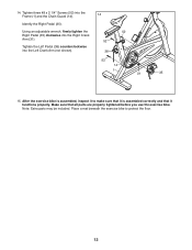
After the exercise bike is assembled correctly and that all parts are properly tightened before you use the exercise bike. Note: Extra parts may be included. Tighten three #8 x 2 1/4" Screws (52) into the Left Crank Arm (not shown). 38 52 14 1 31 35 15. Using an adjustable wrench, firmly tighten the 52 Right Pedal (35) clockwise into the Right Crank Arm (31). 52 Tighten the Left Pedal (38) counterclockwise into the Frame (1) and...
After the exercise bike is assembled correctly and that all parts are properly tightened before you use the exercise bike. Note: Extra parts may be included. Tighten three #8 x 2 1/4" Screws (52) into the Left Crank Arm (not shown). 38 52 14 1 31 35 15. Using an adjustable wrench, firmly tighten the 52 Right Pedal (35) clockwise into the Right Crank Arm (31). 52 Tighten the Left Pedal (38) counterclockwise into the Frame (1) and...

English Manual
Page 13
... the sensor, replace the battery with a new battery of the chest strap into the hole in the location shown. The tab should be within arm’'s length of the battery. •• Store the heart rate monitor in a warm, dry place. side-up. Chest Tabs Strap Sensor Tab The heart rate moni- Then, attach the other container that may keep the sensor activated, shortening the life of the console. •...
... the sensor, replace the battery with a new battery of the chest strap into the hole in the location shown. The tab should be within arm’'s length of the battery. •• Store the heart rate monitor in a warm, dry place. side-up. Chest Tabs Strap Sensor Tab The heart rate moni- Then, attach the other container that may keep the sensor activated, shortening the life of the console. •...
English Manual
Page 14
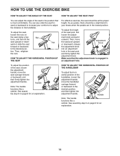
... of the seat to the desired posi- Then, move the seat carriage forward or backward, and then firmly tighten the adjustment handle. Handle Note: The handle functions like a ratchet. ment knob and pull it outward. See assembly step 6 on page 8 for an explanation. tion. HOW TO USE THE EXERCISE BIKE HOW TO ADJUST THE ANGLE OF THE SEAT HOW TO ADJUST THE SEAT POST You...
... of the seat to the desired posi- Then, move the seat carriage forward or backward, and then firmly tighten the adjustment handle. Handle Note: The handle functions like a ratchet. ment knob and pull it outward. See assembly step 6 on page 8 for an explanation. tion. HOW TO USE THE EXERCISE BIKE HOW TO ADJUST THE ANGLE OF THE SEAT HOW TO ADJUST THE SEAT POST You...
English Manual
Page 15
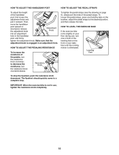
... TO ADJUST THE PEDAL STRAPS To adjust the height of the pedal straps. Resistance Knob To tighten the pedal straps (see the drawing on the buckles, adjust the pedal straps to decrease the resistance, turn the resistance knob clockwise; To loosen the pedal straps, press and hold the tabs on page 5), simply pull the ends of the handlebar post, first loosen the adjustment knob and pull it outward. Leveling Feet To stop . Then, move the...
... TO ADJUST THE PEDAL STRAPS To adjust the height of the pedal straps. Resistance Knob To tighten the pedal straps (see the drawing on the buckles, adjust the pedal straps to decrease the resistance, turn the resistance knob clockwise; To loosen the pedal straps, press and hold the tabs on page 5), simply pull the ends of the handlebar post, first loosen the adjustment knob and pull it outward. Leveling Feet To stop . Then, move the...

English Manual
Page 16
... the lower display. 4. As you use the chest heart rate monitor, the lower display will pause. Scan—-This mode displays the time, calories, speed, and distance, for a few minutes, the console will show the elapsed time and the approximate number of plastic on page 11). You can select information for a few seconds each, in miles per hour). When you are not moved for continuous display. Turn on the console, press the Display Mode button...
... the lower display. 4. As you use the chest heart rate monitor, the lower display will pause. Scan—-This mode displays the time, calories, speed, and distance, for a few minutes, the console will show the elapsed time and the approximate number of plastic on page 11). You can select information for a few seconds each, in miles per hour). When you are not moved for continuous display. Turn on the console, press the Display Mode button...

English Manual
Page 17
... shielded interface cables when connecting to computer or peripheral devices. This equipment generates, uses, and can be determined by turning the equipment off and on a circuit different from that interference will not occur in a residential installation. If this equipment. 17 Changes or modifications not expressly approved by one or more of the FCC Rules. FCC INFORMATION This...
... shielded interface cables when connecting to computer or peripheral devices. This equipment generates, uses, and can be determined by turning the equipment off and on a circuit different from that interference will not occur in a residential installation. If this equipment. 17 Changes or modifications not expressly approved by one or more of the FCC Rules. FCC INFORMATION This...
English Manual
Page 18
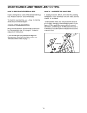
... console problems are the result of the included lubricant in the indicated location on page 13. HOW TO LUBRICATE THE BRAKE PAD If pedaling becomes difficult, even when the pedaling resistance is set to the lowest level, the brake pad may need to stop the flywheel. MAINTENANCE AND TROUBLESHOOTING HOW TO MAINTAIN THE EXERCISE BIKE Inspect and tighten all parts of mild detergent. To clean the exercise bike, use the chest heart rate monitor...
... console problems are the result of the included lubricant in the indicated location on page 13. HOW TO LUBRICATE THE BRAKE PAD If pedaling becomes difficult, even when the pedaling resistance is set to the lowest level, the brake pad may need to stop the flywheel. MAINTENANCE AND TROUBLESHOOTING HOW TO MAINTAIN THE EXERCISE BIKE Inspect and tighten all parts of mild detergent. To clean the exercise bike, use the chest heart rate monitor...
English Manual
Page 19
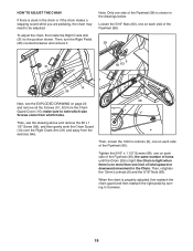
...number of turns until the Chain (28) is tight; Tighten the 5/16" x 1 1/2" Screws (56), one on page 23 and remove all the Screws (51, 52) from the Chain Guard Cover (15); When the chain is properly adjusted, rst reattach the chain guard and then reattach the right pedal by turning...are pedaling, the chain may need to note which size 1" Screws come from which holes. To adjust the chain, rst rotate the Right Crank Arm (...remove the #8 x 1 1/2" Screw (58), and then gently work the Chain Guard (14) over the Right Crank Arm (31) and away from the exercise bike.
...number of turns until the Chain (28) is tight; Tighten the 5/16" x 1 1/2" Screws (56), one on page 23 and remove all the Screws (51, 52) from the Chain Guard Cover (15); When the chain is properly adjusted, rst reattach the chain guard and then reattach the right pedal by turning...are pedaling, the chain may need to note which size 1" Screws come from which holes. To adjust the chain, rst rotate the Right Crank Arm (...remove the #8 x 1 1/2" Screw (58), and then gently work the Chain Guard (14) over the Right Crank Arm (31) and away from the exercise bike.
English Manual
Page 20
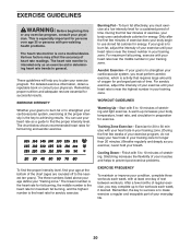
... heart rate monitor is near the highest number in your training zone. (During the first few minutes of the chart (ages are essential for aerobic exercise. For maximum fat burning, exercise with 5 to burn fat, adjust the intensity of your exercise program, do not keep your heart rate in your goal is the heart rate for successful results. WORKOUT GUIDELINES Warming Up—-Start with your heart rate in...
... heart rate monitor is near the highest number in your training zone. (During the first few minutes of the chart (ages are essential for aerobic exercise. For maximum fat burning, exercise with 5 to burn fat, adjust the intensity of your exercise program, do not keep your heart rate in your goal is the heart rate for successful results. WORKOUT GUIDELINES Warming Up—-Start with your heart rate in...
English Manual
Page 22
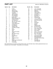
... 2 Short Grooved Axle 46 6 E-clip 47 2 Snap Ring 48 1 Console 49 1 Magnet 50 1 Extension Wire 51 16 #8 x 5/8" Screw 52 3 #8 x 2 1/4" Screw 53 2 5/16" Flange Screw 54 2 3/8" x 2" Screw 55 2 3/8" Locknut 56 2 5/16" x 1 1/2" Screw 57 2 M5 x 20mm Screw 58 1 #8 x 1 1/2" Screw 59 2 1/4" x 1 1/4" Screw 60 1 Water Bottle Holder 61 1 Reed Switch/Wire 62 1 Heart Rate Monitor/Strap 63 2 5/16" Nut * –- User’'s Manual Note: Specifications are not illustrated. 22 Description Key No. Assembly Tool * –- Qty.
... 2 Short Grooved Axle 46 6 E-clip 47 2 Snap Ring 48 1 Console 49 1 Magnet 50 1 Extension Wire 51 16 #8 x 5/8" Screw 52 3 #8 x 2 1/4" Screw 53 2 5/16" Flange Screw 54 2 3/8" x 2" Screw 55 2 3/8" Locknut 56 2 5/16" x 1 1/2" Screw 57 2 M5 x 20mm Screw 58 1 #8 x 1 1/2" Screw 59 2 1/4" x 1 1/4" Screw 60 1 Water Bottle Holder 61 1 Reed Switch/Wire 62 1 Heart Rate Monitor/Strap 63 2 5/16" Nut * –- User’'s Manual Note: Specifications are not illustrated. 22 Description Key No. Assembly Tool * –- Qty.
English Manual
Page 24
... set forth herein. the customer may have other consequential damages of enjoyment or use and service conditions. Labor is authorized by ICON. ICON is shipped to a service center, freight charges to and from defects in connection with respect to provide the following information when contacting us: •• the model number and serial number of the product (see the front cover of this manual...
... set forth herein. the customer may have other consequential damages of enjoyment or use and service conditions. Labor is authorized by ICON. ICON is shipped to a service center, freight charges to and from defects in connection with respect to provide the following information when contacting us: •• the model number and serial number of the product (see the front cover of this manual...


