
User Manual
Page 2
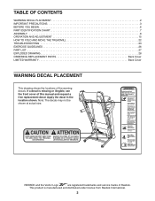
... 15 HOW TO FOLD AND MOVE THE TREADMILL 22 TROUBLESHOOTING 23 EXERCISE GUIDELINES 26 PART LIST 27 EXPLODED DRAWING 28 ORDERING REPLACEMENT PARTS Back Cover LIMITED WARRANTY Back Cover WARNING DECAL PLACEMENT This drawing shows the locations of Reebok. If a decal is manufactured and distributed under license from Reebok International. 2 Note: The decals may not...
... 15 HOW TO FOLD AND MOVE THE TREADMILL 22 TROUBLESHOOTING 23 EXERCISE GUIDELINES 26 PART LIST 27 EXPLODED DRAWING 28 ORDERING REPLACEMENT PARTS Back Cover LIMITED WARRANTY Back Cover WARNING DECAL PLACEMENT This drawing shows the locations of Reebok. If a decal is manufactured and distributed under license from Reebok International. 2 Note: The decals may not...
User Manual
Page 4
... into the off position (see the drawing on page 6 for the location of the treadmill by an authorized service representative. 20. Inspect and properly tighten all parts of heart rate readings. Over exercising may affect the accuracy of the treadmill regularly. The heart rate monitor is running. DANGER: 27. Always unplug the power...
... into the off position (see the drawing on page 6 for the location of the treadmill by an authorized service representative. 20. Inspect and properly tighten all parts of heart rate readings. Over exercising may affect the accuracy of the treadmill regularly. The heart rate monitor is running. DANGER: 27. Always unplug the power...
User Manual
Page 6
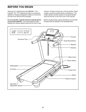
... front cover of this manual. If you , note the product model number and serial number before you for selecting the new REEBOK® 1710 treadmill. Before reading further, please familiarize yourself with the parts that are shown on the front cover of this manual. To help us . The model number and the location of...
... front cover of this manual. If you , note the product model number and serial number before you for selecting the new REEBOK® 1710 treadmill. Before reading further, please familiarize yourself with the parts that are shown on the front cover of this manual. To help us . The model number and the location of...

User Manual
Page 7
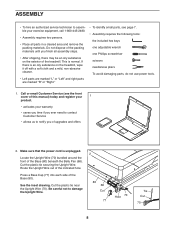
... (7)-2 3/8" x 2" Bolt (12)-2 3/8" x 2 1/2" Bolt (2)- 2 3/8" x 3 1/2" Screw (9)-4 3/8" x 4" Screw (4)-6 7 The number following the key number is the quantity used for assembly. PART IDENTIFICATION CHART Use the drawings below each drawing is the key number of the part, from the PART LIST near the end of this manual. The number in the hardware kit, check to identify small...
... (7)-2 3/8" x 2" Bolt (12)-2 3/8" x 2 1/2" Bolt (2)- 2 3/8" x 3 1/2" Screw (9)-4 3/8" x 4" Screw (4)-6 7 The number following the key number is the quantity used for assembly. PART IDENTIFICATION CHART Use the drawings below each drawing is the key number of the part, from the PART LIST near the end of this manual. The number in the hardware kit, check to identify small...
User Manual
Page 8
... normal. This is unplugged. Cut the plastic tie near the Upright Wire (70). Press a Base Cap (77) into each side of the treadmill. See the inset drawing. Route the Upright Wire out of upgrades and offers 2. Be careful not to notify you finish all assembly steps...; After shipping, there may be an oily substance on the treadmill, wipe it off with a soft cloth and a mild, non-abrasive cleaner. • Left parts are marked "L" or "Left" and right parts are marked "R" or "Right." • To identify small parts, see the front cover of this manual) today and register ...
... normal. This is unplugged. Cut the plastic tie near the Upright Wire (70). Press a Base Cap (77) into each side of the treadmill. See the inset drawing. Route the Upright Wire out of upgrades and offers 2. Be careful not to notify you finish all assembly steps...; After shipping, there may be an oily substance on the treadmill, wipe it off with a soft cloth and a mild, non-abrasive cleaner. • Left parts are marked "L" or "Left" and right parts are marked "R" or "Right." • To identify small parts, see the front cover of this manual) today and register ...
User Manual
Page 14
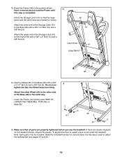
... 22). 2 3 80 81 3 2 81 15. Attach the other Wheel (81) to adjust the walking belt (see HOW TO LOWER THE TREADMILL FOR USE on the treadmill decals, remove the plastic. Note: Extra parts may be included. If there are sheets of the Base (80) in a secure place; Do not over- 14 tighten the... shown) (see pages 24 and 25). 14 Orient the Storage Latch (51) so that all parts are oriented as shown. Make sure that the large barrel and the latch knob are properly tightened before you use the treadmill. Keep the included hex key in the same way. Attach a Wheel (81) to the...
... 22). 2 3 80 81 3 2 81 15. Attach the other Wheel (81) to adjust the walking belt (see HOW TO LOWER THE TREADMILL FOR USE on the treadmill decals, remove the plastic. Note: Extra parts may be included. If there are sheets of the Base (80) in a secure place; Do not over- 14 tighten the... shown) (see pages 24 and 25). 14 Orient the Storage Latch (51) so that all parts are oriented as shown. Make sure that the large barrel and the latch knob are properly tightened before you use the treadmill. Keep the included hex key in the same way. Attach a Wheel (81) to the...
User Manual
Page 26
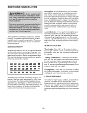
... pre-existing health problems. The heart rate monitor is near the middle number in your training zone. A warm-up to make exercise a regular and enjoyable part of heart rate readings. EXERCISE GUIDELINES WARNING: Before beginning this or any exercise program, consult your heart rate is not a medical device. You can use...
... pre-existing health problems. The heart rate monitor is near the middle number in your training zone. A warm-up to make exercise a regular and enjoyable part of heart rate readings. EXERCISE GUIDELINES WARNING: Before beginning this or any exercise program, consult your heart rate is not a medical device. You can use...
User Manual
Page 27
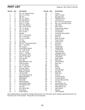
PART LIST Model No. Description Frame Right Foot Rail Storage Latch Right Rear Foot Left Rear Foot #8 x 1/2" Pan Head Screw #8 x 1/2" Controller Screw Idler Roller Motor Hood ... Clip Reed Switch Magnet User's Manual Note: Specifications are not illustrated. 27 RCTL70013.0 R1213A Key No. For information about ordering replacement parts, see the back cover of this manual. *These parts are subject to change without notice. Qty. 1 4 2 2 3 4 4 6 5 10 6 41 7 2 8 2 9 4 10 4 11 10 12 2 13 2 14 2 15 2 16 2 17 2 18 3 19 19...
PART LIST Model No. Description Frame Right Foot Rail Storage Latch Right Rear Foot Left Rear Foot #8 x 1/2" Pan Head Screw #8 x 1/2" Controller Screw Idler Roller Motor Hood ... Clip Reed Switch Magnet User's Manual Note: Specifications are not illustrated. 27 RCTL70013.0 R1213A Key No. For information about ordering replacement parts, see the back cover of this manual. *These parts are subject to change without notice. Qty. 1 4 2 2 3 4 4 6 5 10 6 41 7 2 8 2 9 4 10 4 11 10 12 2 13 2 14 2 15 2 16 2 17 2 18 3 19 19...
User Manual
Page 32
... (customer). This warranty provides specific legal rights; Some provinces do not allow limitations on how long an implied warranty lasts. Parts and labor are made must be responsible for which warranty claims are warranted for one of this manual) • the key number ...and description of the replacement part(s) (see the PART LIST and the EXPLODED DRAWING near the end of its authorized service centers. damages with an extended service plan, see page 5....
... (customer). This warranty provides specific legal rights; Some provinces do not allow limitations on how long an implied warranty lasts. Parts and labor are made must be responsible for which warranty claims are warranted for one of this manual) • the key number ...and description of the replacement part(s) (see the PART LIST and the EXPLODED DRAWING near the end of its authorized service centers. damages with an extended service plan, see page 5....


