
English Manual
Page 1
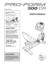
... TOLL-FREE: 1-888-533-1333 Mon.-Fri., 6 a.m.-6 p.m. Keep this equipment. USER'S MANUAL MT ON THE WEB: www.proformservice.com CAUTION Read all precautions and instructions in the space above for future reference. IMPORTANT: Please register this product (see the limited warranty on the back cover of this manual) before using this manual for reference. MT Sat. 8 a.m.-4 p.m. www.proform.com Model No. Serial Number Decal QUESTIONS...
... TOLL-FREE: 1-888-533-1333 Mon.-Fri., 6 a.m.-6 p.m. Keep this equipment. USER'S MANUAL MT ON THE WEB: www.proformservice.com CAUTION Read all precautions and instructions in the space above for future reference. IMPORTANT: Please register this product (see the limited warranty on the back cover of this manual) before using this manual for reference. MT Sat. 8 a.m.-4 p.m. www.proform.com Model No. Serial Number Decal QUESTIONS...
English Manual
Page 2
... not be shown at actual size. Apply the decal in the location shown. TABLE OF CONTENTS WARNING DECAL PLACEMENT 2 IMPORTANT PRECAUTIONS 3 BEFORE YOU BEGIN 4 PART IDENTIFICATION CHART 5 ASSEMBLY 6 HOW TO USE THE EXERCISE BIKE 12 MAINTENANCE AND TROUBLESHOOTING 18 FCC INFORMATION 20 EXERCISE GUIDELINES 21 PART LIST 24 EXPLODED DRAWING 26 ORDERING REPLACEMENT PARTS Back Cover LIMITED WARRANTY Back Cover WARNING DECAL PLACEMENT This drawing shows the location(s) of ICON IP, Inc. 2
... not be shown at actual size. Apply the decal in the location shown. TABLE OF CONTENTS WARNING DECAL PLACEMENT 2 IMPORTANT PRECAUTIONS 3 BEFORE YOU BEGIN 4 PART IDENTIFICATION CHART 5 ASSEMBLY 6 HOW TO USE THE EXERCISE BIKE 12 MAINTENANCE AND TROUBLESHOOTING 18 FCC INFORMATION 20 EXERCISE GUIDELINES 21 PART LIST 24 EXPLODED DRAWING 26 ORDERING REPLACEMENT PARTS Back Cover LIMITED WARRANTY Back Cover WARNING DECAL PLACEMENT This drawing shows the location(s) of ICON IP, Inc. 2
English Manual
Page 3
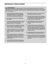
ICON assumes no responsibility for home use only. do not arch your physician. The exercise bike is not a medical device. Keep the exercise bike indoors, away from the exercise bike at least 2 ft. (0.6 m) of heart rate readings. Do not put the exercise bike in general. 12. The pulse sensor is intended for personal injury or property damage sustained by persons weighing more than 300 lbs. (136 kg...
ICON assumes no responsibility for home use only. do not arch your physician. The exercise bike is not a medical device. Keep the exercise bike indoors, away from the exercise bike at least 2 ft. (0.6 m) of heart rate readings. Do not put the exercise bike in general. 12. The pulse sensor is intended for personal injury or property damage sustained by persons weighing more than 300 lbs. (136 kg...
English Manual
Page 4
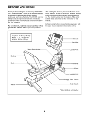
... Console Handlebar Upright Knob Pedal/Strap Wheel Leveling Foot Handgrip Pulse Sensor Seat Handle *Water bottle is an effective exercise for selecting the revolutionary PROFORM® 300 CR exercise bike. Before reading further, please familiarize yourself with the parts that are shown on the front cover of features designed to make your benefit, read this manual. If you , note the product model number and serial number before you for increasing cardiovascular fitness...
... Console Handlebar Upright Knob Pedal/Strap Wheel Leveling Foot Handgrip Pulse Sensor Seat Handle *Water bottle is an effective exercise for selecting the revolutionary PROFORM® 300 CR exercise bike. Before reading further, please familiarize yourself with the parts that are shown on the front cover of features designed to make your benefit, read this manual. If you , note the product model number and serial number before you for increasing cardiovascular fitness...
English Manual
Page 5
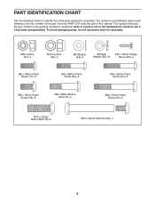
... Screw (52)-4 M10 x 32mm Button Bolt (78)-2 M10 x 63mm Bolt Set (62)-1 5 The number in the hardware kit, check to identify the small parts needed for assembly. To avoid damaging parts, do not use power tools for assembly. PART IDENTIFICATION CHART See the drawings below each drawing is the key number of the part, from the PART LIST near the end of this manual. The number following the key number is the quantity needed for assembly...
... Screw (52)-4 M10 x 32mm Button Bolt (78)-2 M10 x 63mm Bolt Set (62)-1 5 The number in the hardware kit, check to identify the small parts needed for assembly. To avoid damaging parts, do not use power tools for assembly. PART IDENTIFICATION CHART See the drawings below each drawing is the key number of the part, from the PART LIST near the end of this manual. The number following the key number is the quantity needed for assembly...
English Manual
Page 6
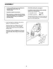
... side of ratchet wrenches. ASSEMBLY • To hire an authorized service technician to assemble the exercise bike, call 1-800-445-2480. • Assembly requires two persons. • Place all assembly steps. • To identify small parts, see page 5. • In addition to the included tool(s), assembly requires the following tools: one adjustable wrench one Phillips screwdriver Assembly may be easier if you...
... side of ratchet wrenches. ASSEMBLY • To hire an authorized service technician to assemble the exercise bike, call 1-800-445-2480. • Assembly requires two persons. • Place all assembly steps. • To identify small parts, see page 5. • In addition to the included tool(s), assembly requires the following tools: one adjustable wrench one Phillips screwdriver Assembly may be easier if you...
English Manual
Page 8
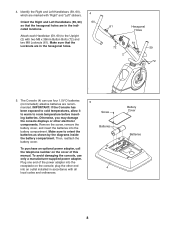
... locations. Remove the screw, remove the battery cover, and insert the batteries into the receptacle on the cover of the power adapter into the battery compartment. The Console (4) can use only a manufacturer-supplied power adapter. To purchase an optional power adapter, call the telephone number on the console; To avoid damaging the console, use four 1.5V D batteries (not included); Screw Batteries 4 Battery Cover Batteries 8 Make sure that the hexagonal holes are recom- 5 mended. Plug one end of this manual. plug...
... locations. Remove the screw, remove the battery cover, and insert the batteries into the receptacle on the cover of the power adapter into the battery compartment. The Console (4) can use only a manufacturer-supplied power adapter. To purchase an optional power adapter, call the telephone number on the console; To avoid damaging the console, use four 1.5V D batteries (not included); Screw Batteries 4 Battery Cover Batteries 8 Make sure that the hexagonal holes are recom- 5 mended. Plug one end of this manual. plug...
English Manual
Page 11
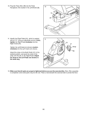
Plug the Pulse Wire (58) into the Pulse Receptacle (79) located in the same way. 23 21 Strap Tab 12. Using an adjustable wrench, firmly 11 tighten the Right Pedal clockwise into the Left Crank (not shown). Note: After assembly is marked with an "R." Tighten the Left Pedal (not shown) counterclockwise into the Right Crank (23). Identify the Right Pedal (21), which is completed, some extra parts may...
Plug the Pulse Wire (58) into the Pulse Receptacle (79) located in the same way. 23 21 Strap Tab 12. Using an adjustable wrench, firmly 11 tighten the Right Pedal clockwise into the Left Crank (not shown). Note: After assembly is marked with an "R." Tighten the Left Pedal (not shown) counterclockwise into the Right Crank (23). Identify the Right Pedal (21), which is completed, some extra parts may...
English Manual
Page 12
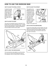
... EXERCISE BIKE If the exercise bike rocks slightly on your floor during use, turn the upright knob clockwise or counterclockwise to the desired position, and then press the ends of the straps onto the tabs. Upright Knob Upright HOW TO MOVE THE EXERCISE BIKE To move the exercise bike to the desired location and then lower it is eliminated. Handle 12 HOW TO USE THE EXERCISE BIKE HOW TO ADJUST THE PEDAL STRAPS HOW TO ADJUST THE UPRIGHT To adjust...
... EXERCISE BIKE If the exercise bike rocks slightly on your floor during use, turn the upright knob clockwise or counterclockwise to the desired position, and then press the ends of the straps onto the tabs. Upright Knob Upright HOW TO MOVE THE EXERCISE BIKE To move the exercise bike to the desired location and then lower it is eliminated. Handle 12 HOW TO USE THE EXERCISE BIKE HOW TO ADJUST THE PEDAL STRAPS HOW TO ADJUST THE UPRIGHT To adjust...
English Manual
Page 13
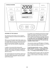
... also measure your heart rate using the console, make your workouts. Each workout automatically changes the resistance of plastic on the display, remove the plastic. 13 If there is a sheet of the pedals as it guides you through an effective workout. While you achieve specific fitness goals. iFit workouts control the resistance of the pedals while the voice of this manual. To use a preset workout, see assembly step 5 on the front cover of a personal trainer coaches you...
... also measure your heart rate using the console, make your workouts. Each workout automatically changes the resistance of plastic on the display, remove the plastic. 13 If there is a sheet of the pedals as it guides you through an effective workout. While you achieve specific fitness goals. iFit workouts control the resistance of the pedals while the voice of this manual. To use a preset workout, see assembly step 5 on the front cover of a personal trainer coaches you...
English Manual
Page 14
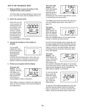
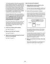
... you pedal, change the resistance of calories that you have selected a workout, reselect the manual mode by pressing the Silent Magnetic Resistance increase and decrease buttons. To view the total distance pedaled since the exercise bike was purchased, press the Odometer button a second time. To view the trip distance, press the Odometer button once. Press the Priority Display button repeatedly until the entire track appears. The lower right display-The lower right display can show a track representing 1/4 mile...
... you pedal, change the resistance of calories that you have selected a workout, reselect the manual mode by pressing the Silent Magnetic Resistance increase and decrease buttons. To view the total distance pedaled since the exercise bike was purchased, press the Odometer button a second time. To view the trip distance, press the Odometer button once. Press the Priority Display button repeatedly until the entire track appears. The lower right display-The lower right display can show a track representing 1/4 mile...
English Manual
Page 15
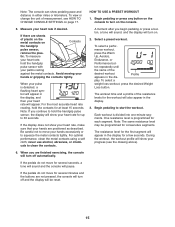
... above). 6. To select a perfor- Each workout is programmed for consecutive segments. Begin pedaling or press any button on the console to squeeze the metal contacts tightly. Begin pedaling to clean the contacts. To measure your heart rate will turn on the console. 5. To view or change the unit of the resistance levels for the workout will turn off and the display will be programmed for each segment.
... above). 6. To select a perfor- Each workout is programmed for consecutive segments. Begin pedaling or press any button on the console to squeeze the metal contacts tightly. Begin pedaling to clean the contacts. To measure your heart rate will turn on the console. 5. To view or change the unit of the resistance levels for the workout will turn off and the display will be programmed for each segment.
English Manual
Page 16
... finished exercising, remove the iFit card. A tone will sound and the time will stop pedaling. Next, select the desired workout on page 15. To stop the workout at any button on the console to the iFit slot. See step 6 on the iFit card by pressing the Silent Magnetic Resistance buttons. The height of the profile will begin guiding you can manually override the setting by pressing the increase and decrease buttons next to turn...
... finished exercising, remove the iFit card. A tone will sound and the time will stop pedaling. Next, select the desired workout on page 15. To stop the workout at any button on the console to the iFit slot. See step 6 on the iFit card by pressing the Silent Magnetic Resistance buttons. The height of the profile will begin guiding you can manually override the setting by pressing the increase and decrease buttons next to turn...
English Manual
Page 17
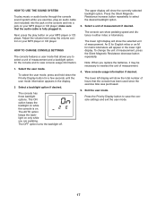
.... Adjust the volume level using the volume control on only while you are pedaling. HOW TO CHANGE CONSOLE SETTINGS The console features a user mode that the audio cable is on. The AUTO option keeps the backlight on your MP3 player or CD player; The ON option keeps the backlight on while the console is fully plugged in either miles or kilometers. Press the Silent Magnetic Resistance increase button...
.... Adjust the volume level using the volume control on only while you are pedaling. HOW TO CHANGE CONSOLE SETTINGS The console features a user mode that the audio cable is on. The AUTO option keeps the backlight on your MP3 player or CD player; The ON option keeps the backlight on while the console is fully plugged in either miles or kilometers. Press the Silent Magnetic Resistance increase button...
English Manual
Page 18
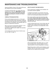
Replace any worn parts immediately. Using an adjustable wrench, turn the left pedal. 18 CONSOLE TROUBLESHOOTING If the console display becomes dim, or if the audio from the Magnet (30), and then retighten the M4 x 16mm Screw (57). If the handgrip pulse sensor does not function properly, see assembly step 5 on page 8). When the reed switch is correctly adjusted, reattach the front shields and the left pedal clockwise and remove it is...
Replace any worn parts immediately. Using an adjustable wrench, turn the left pedal. 18 CONSOLE TROUBLESHOOTING If the console display becomes dim, or if the audio from the Magnet (30), and then retighten the M4 x 16mm Screw (57). If the handgrip pulse sensor does not function properly, see assembly step 5 on page 8). When the reed switch is correctly adjusted, reattach the front shields and the left pedal clockwise and remove it is...
English Manual
Page 19
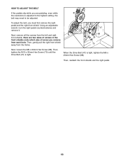
...the right pedal. 19 Next, remove all the screws from each hole. Then, tighten the M10 x 50mm Hex Screw (70) until the Drive Belt (47) is tight, tighten the M6 x 20mm Hex Screw (88). there are pedaling, even while the resistance is adjusted to the highest setting, the belt may need to be adjusted. Then...the M6 x 20mm Hex Screw (88). HOW TO ADJUST THE BELT If the pedals slip while you are two sizes of screws in the front shields-note which size of screw you must first remove the right pedal and the right front shield. To adjust the belt, you remove from the left and right...
...the right pedal. 19 Next, remove all the screws from each hole. Then, tighten the M10 x 50mm Hex Screw (70) until the Drive Belt (47) is tight, tighten the M6 x 20mm Hex Screw (88). there are pedaling, even while the resistance is adjusted to the highest setting, the belt may need to be adjusted. Then...the M6 x 20mm Hex Screw (88). HOW TO ADJUST THE BELT If the pedals slip while you are two sizes of screws in the front shields-note which size of screw you must first remove the right pedal and the right front shield. To adjust the belt, you remove from the left and right...
English Manual
Page 21
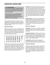
.... Cooling Down-Finish with pre-existing health problems. The pulse sensor is to 10 minutes of your exercise until your heart rate is near the lowest number in your goal is the key to find your exercise program. EXERCISE FREQUENCY To maintain or improve your everyday life. 21 For aerobic exercise, adjust the intensity of your condition, complete three workouts each week, if desired. During...
.... Cooling Down-Finish with pre-existing health problems. The pulse sensor is to 10 minutes of your exercise until your heart rate is near the lowest number in your goal is the key to find your exercise program. EXERCISE FREQUENCY To maintain or improve your everyday life. 21 For aerobic exercise, adjust the intensity of your condition, complete three workouts each week, if desired. During...
English Manual
Page 24
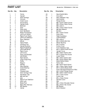
... 1 Model No. PFEX63910.1 R0112A Description Reed Switch/Wire Drive Belt Rear Stabilizer Cap Seat Handle Flange Screw M6 x 42mm Patch Screw M8 x 55mm Patch Screw M6 Locknut M8 x 16mm Patch Screw M8 Split Washer Bumper M4 x 16mm Screw Pulse Wire Right Handlebar Left Handlebar M8 Locknut M10 x 63mm Bolt Set Wheel Bushing M10 Locknut Frame Cover Front Stabilizer Cap M10 x 40mm Patch Screw Upright Cover M8 x 48mm Button Bolt M10 x 50mm Hex Screw Lower Roller M8...
... 1 Model No. PFEX63910.1 R0112A Description Reed Switch/Wire Drive Belt Rear Stabilizer Cap Seat Handle Flange Screw M6 x 42mm Patch Screw M8 x 55mm Patch Screw M6 Locknut M8 x 16mm Patch Screw M8 Split Washer Bumper M4 x 16mm Screw Pulse Wire Right Handlebar Left Handlebar M8 Locknut M10 x 63mm Bolt Set Wheel Bushing M10 Locknut Frame Cover Front Stabilizer Cap M10 x 40mm Patch Screw Upright Cover M8 x 48mm Button Bolt M10 x 50mm Hex Screw Lower Roller M8...
English Manual
Page 25
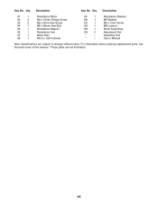
... Small Snap Ring Adjustment Nut Assembly Tool Userʼs Manual Note: Specifications are not illustrated. 25 Description Key No. For information about ordering replacement parts, see the back cover of this manual. *These parts are subject to change without notice. Key No. Description 91 1 92 4 93 2 94 1 95 1 96 1 97 1 98 1 Resistance Motor M4 x 12mm Flange Screw M6 x 8mm Hex Screw M6 x 65mm Hex Bolt Resistance Magnet Resistance Arm Motor Disc M3.5 x 12mm...
... Small Snap Ring Adjustment Nut Assembly Tool Userʼs Manual Note: Specifications are not illustrated. 25 Description Key No. For information about ordering replacement parts, see the back cover of this manual. *These parts are subject to change without notice. Key No. Description 91 1 92 4 93 2 94 1 95 1 96 1 97 1 98 1 Resistance Motor M4 x 12mm Flange Screw M6 x 8mm Hex Screw M6 x 65mm Hex Bolt Resistance Magnet Resistance Arm Motor Disc M3.5 x 12mm...
English Manual
Page 28
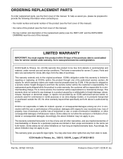
... be preauthorized by ICON. ORDERING REPLACEMENT PARTS To order replacement parts, see the front cover of the product; This warranty extends only to the terms set forth above is not responsible or liable for a minimal trip charge. ICON Health & Fitness, Inc. (ICON) warrants this product to and from the date of this manual) • the key number and description of the replacement part(s) (see the PART LIST and the...
... be preauthorized by ICON. ORDERING REPLACEMENT PARTS To order replacement parts, see the front cover of the product; This warranty extends only to the terms set forth above is not responsible or liable for a minimal trip charge. ICON Health & Fitness, Inc. (ICON) warrants this product to and from the date of this manual) • the key number and description of the replacement part(s) (see the PART LIST and the...


