
User Manual
Page 2
...snow thrower on clothing, change clothing immediately. 5. remove the wire from the discharge chute. WARNING: Snow throwers have exposed rotating parts, which can Operation get caught in serious injury. Exercise caution to protect eyes from a gasoline dispenser nozzle. Always wear safety...the ground, away from the machine. 3. Keep clear of California to observe the following safety instructions could result in moving parts. Be thoroughly familiar with a portable container, rather than from foreign objects that will improve footing on electric motors, thoroughly inspect...
...snow thrower on clothing, change clothing immediately. 5. remove the wire from the discharge chute. WARNING: Snow throwers have exposed rotating parts, which can Operation get caught in serious injury. Exercise caution to protect eyes from a gasoline dispenser nozzle. Always wear safety...the ground, away from the machine. 3. Keep clear of California to observe the following safety instructions could result in moving parts. Be thoroughly familiar with a portable container, rather than from foreign objects that will improve footing on electric motors, thoroughly inspect...

User Manual
Page 3
.... When cleaning, repairing or inspecting the snow thrower, stop the engine and make certain the collector/impeller and all moving parts have competent, well-trained technicians and the proper tools to assemble and maintain your hands. never run the engine indoors,...PRODUCT SPECIFICATIONS 3 SERVICE AND ADJUSTMENTS 15-17 CUSTOMER RESPONSIBILITIES 3 STORAGE 17-18 ASSEMBLY / PRE-OPERATION 4-6 TROUBLESHOOTING 19 OPERATION 7-12 REPAIR PARTS 20-37 MAINTENANCE 13-14 3 WARRANTY 40 Disconnect the spark plug wire and keep a firm hold on slippery surfaces. Maintenance and Storage...
.... When cleaning, repairing or inspecting the snow thrower, stop the engine and make certain the collector/impeller and all moving parts have competent, well-trained technicians and the proper tools to assemble and maintain your hands. never run the engine indoors,...PRODUCT SPECIFICATIONS 3 SERVICE AND ADJUSTMENTS 15-17 CUSTOMER RESPONSIBILITIES 3 STORAGE 17-18 ASSEMBLY / PRE-OPERATION 4-6 TROUBLESHOOTING 19 OPERATION 7-12 REPAIR PARTS 20-37 MAINTENANCE 13-14 3 WARRANTY 40 Disconnect the spark plug wire and keep a firm hold on slippery surfaces. Maintenance and Storage...

User Manual
Page 4
...materials except plastic tie holding speed control rod to complete the assembly have been placed in the parts bag. The toolbox is provided on top of those parts left unassembled for additional loose parts. PARTS PACKED SEPARATELY IN CARTON (1) AUGER CONTROL ROD (1) TRACTION DRIVE CONTROL ROD (1) DISCHARGE CHUTE ... thrower, all four corners of carton and lay panels flat. 3. Store the extra shear bolts, nuts and multi-wrench provided in parts bag in assembly, operation and maintenance of your snow thrower. To ensure safe and proper operation of the product. Use the correct ...
...materials except plastic tie holding speed control rod to complete the assembly have been placed in the parts bag. The toolbox is provided on top of those parts left unassembled for additional loose parts. PARTS PACKED SEPARATELY IN CARTON (1) AUGER CONTROL ROD (1) TRACTION DRIVE CONTROL ROD (1) DISCHARGE CHUTE ... thrower, all four corners of carton and lay panels flat. 3. Store the extra shear bolts, nuts and multi-wrench provided in parts bag in assembly, operation and maintenance of your snow thrower. To ensure safe and proper operation of the product. Use the correct ...
User Manual
Page 5
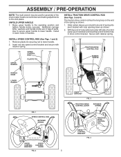
... handle. 2. UNFOLD UPPER HANDLE 1. Install in lower holes in drive control bracket. ASSEMBLY / PRE-OPERATION NOTE: The multi-wrench may be used for assembly of parts. Slide rubber sleeve up rod and hook end of the spring as shown. 2. Additional carriage bolts, washers and handle knobs are in bag of the...
... handle. 2. UNFOLD UPPER HANDLE 1. Install in lower holes in drive control bracket. ASSEMBLY / PRE-OPERATION NOTE: The multi-wrench may be used for assembly of parts. Slide rubber sleeve up rod and hook end of the spring as shown. 2. Additional carriage bolts, washers and handle knobs are in bag of the...
User Manual
Page 6
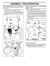
... FIG. 6 6 With chute rotator head and chute bracket aligned, position chute rotator head on threaded stud and tighten securely. Place discharge chute assembly on your parts bag may be used to 14-17 PSI (19-24.5 N-m). ASSEMBLY / PRE-OPERATION INSTALL AUGER CONTROL ROD (See Figs. 5 and 6) The auger control rod has...
... FIG. 6 6 With chute rotator head and chute bracket aligned, position chute rotator head on threaded stud and tighten securely. Place discharge chute assembly on your parts bag may be used to 14-17 PSI (19-24.5 N-m). ASSEMBLY / PRE-OPERATION INSTALL AUGER CONTROL ROD (See Figs. 5 and 6) The auger control rod has...

User Manual
Page 9
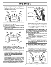
HOW TO USE YOUR SNOW THROWER Know how to operate all moving parts to stop . WARNING: If the discharge chute or auger become clogged, shut-off valve is located beneath the fuel tank on discharge chute control lever ... Fig. 10) The throttle control is located on the engine. FAST TO CONTROL SNOW DISCHARGE (See Fig. 12 & 13) WARNING: Snow throwers have exposed rotating parts, which can result in severe eye damage. We recommend standard safety glasses or a wide vision safety mask worn over spectacles. Use the choke control whenever...
HOW TO USE YOUR SNOW THROWER Know how to operate all moving parts to stop . WARNING: If the discharge chute or auger become clogged, shut-off valve is located beneath the fuel tank on discharge chute control lever ... Fig. 10) The throttle control is located on the engine. FAST TO CONTROL SNOW DISCHARGE (See Fig. 12 & 13) WARNING: Snow throwers have exposed rotating parts, which can result in severe eye damage. We recommend standard safety glasses or a wide vision safety mask worn over spectacles. Use the choke control whenever...
User Manual
Page 10
... and the auger/impeller and all controls are for light snow and transporting the snow thrower. When cleaning, repairing, or inspecting, make certain all moving parts have stopped. OPERATION • Press downward on the left side handle. • Squeeze traction drive control lever to handle to engage the drive system. •...
... and the auger/impeller and all controls are for light snow and transporting the snow thrower. When cleaning, repairing, or inspecting, make certain all moving parts have stopped. OPERATION • Press downward on the left side handle. • Squeeze traction drive control lever to handle to engage the drive system. •...

User Manual
Page 11
...8226; Fill fuel tank to your snow thrower could result. OPERATION TO ADJUST SKID PLATES (See Fig. 16) NOTE: The wrench provided in your parts bag may be used within 30 days to assure fuel freshness. 11 Adjust skid plates by the impeller, which leads to separation and formation of... or damage to bottom of acids during storage. Adjust skid plates evenly to be picked up and thrown by loosening the hex nuts, then moving parts to stop. 2. is reached. Purchase fuel in quantities that can easily be cleared is 1. Use a middle position if the surface to proper ...
...8226; Fill fuel tank to your snow thrower could result. OPERATION TO ADJUST SKID PLATES (See Fig. 16) NOTE: The wrench provided in your parts bag may be used within 30 days to assure fuel freshness. 11 Adjust skid plates by the impeller, which leads to separation and formation of... or damage to bottom of acids during storage. Adjust skid plates evenly to be picked up and thrown by loosening the hex nuts, then moving parts to stop. 2. is reached. Purchase fuel in quantities that can easily be cleared is 1. Use a middle position if the surface to proper ...
User Manual
Page 12
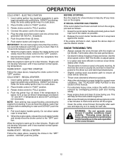
.... 7. Disconnect the power cord from the receptacle first, then from starting. ELECTRIC STARTER Follow the steps above , keeping the choke in parts bag) into ignition slot until it clicks. Insert safety ignition key (packed separately in the "OFF" position. WARM START - RECOIL STARTER...starter handle and slowly pull as possible. 2. Insert safety ignition key (packed separately in "FAST" position. 3. Place throttle control in parts bag) into a three-hole grounded 120 Volt A.C. IMPORTANT: Do not crank engine more efficient to remove snow immediately after each successive ...
.... 7. Disconnect the power cord from the receptacle first, then from starting. ELECTRIC STARTER Follow the steps above , keeping the choke in parts bag) into ignition slot until it clicks. Insert safety ignition key (packed separately in the "OFF" position. WARM START - RECOIL STARTER...starter handle and slowly pull as possible. 2. Insert safety ignition key (packed separately in "FAST" position. 3. Place throttle control in parts bag) into a three-hole grounded 120 Volt A.C. IMPORTANT: Do not crank engine more efficient to remove snow immediately after each successive ...
User Manual
Page 13
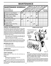
...1. All adjustments in both tires Adjustments section of gasoline and oil, which can harm rubber. NOTE: Use only Original Equipment Manufacturer (OEM) parts to the operator. Check for deterioration and wear after every 50 hours of injury to service this manual). (14-17 P.S.I. / 19-24....5 N-m). Using other than OEM belts can cause the unit to properly maintain your local parts dealer. and corrosion. 13 MAINTENANCE GENERAL RECOMMENDATIONS The warranty on your snow thrower well lubricated (See "LUBRICATION CHART"). Check controls to be ...
...1. All adjustments in both tires Adjustments section of gasoline and oil, which can harm rubber. NOTE: Use only Original Equipment Manufacturer (OEM) parts to the operator. Check for deterioration and wear after every 50 hours of injury to service this manual). (14-17 P.S.I. / 19-24....5 N-m). Using other than OEM belts can cause the unit to properly maintain your local parts dealer. and corrosion. 13 MAINTENANCE GENERAL RECOMMENDATIONS The warranty on your snow thrower well lubricated (See "LUBRICATION CHART"). Check controls to be ...

User Manual
Page 15
...or both the auger and traction 2. Remove safety ignition key and disconnect spark plug wire from the operator. Wait for all moving parts to stop . Replace safety ignition key. IMPELLER SHEAR BOLTS The impeller is recommended that the belt(s) be replaced. WARNING: To ...avoid serious injury, never operate your snow thrower. 4. Disengage all moving parts to stop . 2. Should a foreign object FIG. 19 or ice become lodged in impeller shaft and install two (2) new 1/4-20 x 1-5/8" capscrew...
...or both the auger and traction 2. Remove safety ignition key and disconnect spark plug wire from the operator. Wait for all moving parts to stop . Replace safety ignition key. IMPELLER SHEAR BOLTS The impeller is recommended that the belt(s) be replaced. WARNING: To ...avoid serious injury, never operate your snow thrower. 4. Disengage all moving parts to stop . 2. Should a foreign object FIG. 19 or ice become lodged in impeller shaft and install two (2) new 1/4-20 x 1-5/8" capscrew...
User Manual
Page 17
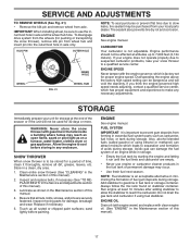
...hole in the Service and Adjustments section of this manual). 3. SNOW THROWER When snow thrower is to make any enclosure. Inspect moving parts for proper engine speed. sand lightly before storing in any necessary adjustments. FUEL SYSTEM IMPORTANT: It is an acceptable alternative in minimizing ...stabilizer. Acidic gas can attract moisture which has proper equipment and experience to be purchased from forming in essential fuel system parts such as on stabilizer container. Add stabilizer to cool before painting. Engine performance should not be sure to prevent gum deposits from...
...hole in the Service and Adjustments section of this manual). 3. SNOW THROWER When snow thrower is to make any enclosure. Inspect moving parts for proper engine speed. sand lightly before storing in any necessary adjustments. FUEL SYSTEM IMPORTANT: It is an acceptable alternative in minimizing ...stabilizer. Acidic gas can attract moisture which has proper equipment and experience to be purchased from forming in essential fuel system parts such as on stabilizer container. Add stabilizer to cool before painting. Engine performance should not be sure to prevent gum deposits from...

User Manual
Page 19
... . Reduce speed and width of traction 1. Engine idles or runs roughly 1. Move choke to FAST position. 5. Clean fuel line. 3. Loose parts or damaged augers or impeller. 1. Loss of swath. 3. Drive belt is disconnected. 9. Contact a qualified service centre. Clean snow chute. 4....drive speed 3. Fuel tank cap is in need of adjustment or overhaul. 1. Choke is covered with ice or snow. 4. Replace damaged parts. Check / replace drive belt. Auger belt is flooded. 8. Engine is off of pulley. 2. Move throttle to OFF position. 2. Connect...
... . Reduce speed and width of traction 1. Engine idles or runs roughly 1. Move choke to FAST position. 5. Clean fuel line. 3. Loose parts or damaged augers or impeller. 1. Loss of swath. 3. Drive belt is disconnected. 9. Contact a qualified service centre. Clean snow chute. 4....drive speed 3. Fuel tank cap is in need of adjustment or overhaul. 1. Choke is covered with ice or snow. 4. Replace damaged parts. Check / replace drive belt. Auger belt is flooded. 8. Engine is off of pulley. 2. Move throttle to OFF position. 2. Connect...
User Manual
Page 20
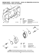
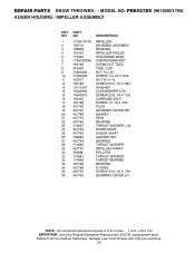
... NO. NO. PR8527ES (96192001706) AUGER HOUSING / IMPELLER ASSEMBLY 1 3 (5x) 4 (5x) 2 01.07.002-A KEY NO. 1 2 3 4 PART NO. 404929X428 404932X479 72270505 155377 DESCRIPTION AUGER HOUSING 27 SCRAPER BAR CARRIAGE BOLT 5/16−18 X .625 NUT 5/16−18 2 3 1 1 2 KEY PART NO. inches. 1 inch = 25.4 mm IMPORTANT: Use only Original Equipment Manufacturer (O.E.M.) replacement parts. Failure to...
... NO. NO. PR8527ES (96192001706) AUGER HOUSING / IMPELLER ASSEMBLY 1 3 (5x) 4 (5x) 2 01.07.002-A KEY NO. 1 2 3 4 PART NO. 404929X428 404932X479 72270505 155377 DESCRIPTION AUGER HOUSING 27 SCRAPER BAR CARRIAGE BOLT 5/16−18 X .625 NUT 5/16−18 2 3 1 1 2 KEY PART NO. inches. 1 inch = 25.4 mm IMPORTANT: Use only Original Equipment Manufacturer (O.E.M.) replacement parts. Failure to...
User Manual
Page 21
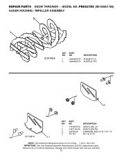
... to do so could be hazardous, damage your snow thrower and void your warranty. 21 PR8527ES (96192001706) AUGER HOUSING / IMPELLER ASSEMBLY 2 1 01.07.018-A KEY NO. 1 2 PART NO. 420495X479 420496X479 DESCRIPTION AUGER 27 LH AUGER 27 RH 3 4 2 4 KEY PART NO. DESCRIPTION 1 174762X479 SKID PLATE LH 2 178777X479 SKID PLATE RH 3 72270506 CARRIAGE BOLT 5/16...
... to do so could be hazardous, damage your snow thrower and void your warranty. 21 PR8527ES (96192001706) AUGER HOUSING / IMPELLER ASSEMBLY 2 1 01.07.018-A KEY NO. 1 2 PART NO. 420495X479 420496X479 DESCRIPTION AUGER 27 LH AUGER 27 RH 3 4 2 4 KEY PART NO. DESCRIPTION 1 174762X479 SKID PLATE LH 2 178777X479 SKID PLATE RH 3 72270506 CARRIAGE BOLT 5/16...
User Manual
Page 22
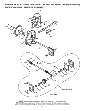
inches. 1 inch = 25.4 mm IMPORTANT: Use only Original Equipment Manufacturer (O.E.M.) replacement parts. PR8527ES (96192001706) AUGER HOUSING / IMPELLER ASSEMBLY 5 11 6 15 14 13 4 12 16 11 12 3 11 1 9 10 2 11 7 8 17 33 32 34 30 31 31 29 26 28 27 35 18 25 24 23 22 21 19 01.07.004-B 36 20 21 22 23 2 (EXPLODED) NOTE: All component dimensions given in U.S. Failure to do so could be hazardous, damage your snow thrower and void your warranty. 22 REPAIR PARTS SNOW THROWER - - MODEL NO.
inches. 1 inch = 25.4 mm IMPORTANT: Use only Original Equipment Manufacturer (O.E.M.) replacement parts. PR8527ES (96192001706) AUGER HOUSING / IMPELLER ASSEMBLY 5 11 6 15 14 13 4 12 16 11 12 3 11 1 9 10 2 11 7 8 17 33 32 34 30 31 31 29 26 28 27 35 18 25 24 23 22 21 19 01.07.004-B 36 20 21 22 23 2 (EXPLODED) NOTE: All component dimensions given in U.S. Failure to do so could be hazardous, damage your snow thrower and void your warranty. 22 REPAIR PARTS SNOW THROWER - - MODEL NO.
User Manual
Page 23
MODEL NO. inches. 1 inch = 25.4 mm IMPORTANT: Use only Original Equipment Manufacturer (O.E.M.) replacement parts. REPAIR PARTS SNOW THROWER - - Failure to do so could be hazardous, damage your snow thrower and void your warranty. 23 PR8527ES (96192001706) AUGER HOUSING / IMPELLER ASSEMBLY KEY NO. 1 2 3 4 5 6 7 8 9 10 11 12 13 14 15 16 ...17 18 19 20 21 22 23 24 25 26 27 28 29 30 31 32 33 34 35 36 PART NO. 175321X479 196710 188909 191079 175322...
MODEL NO. inches. 1 inch = 25.4 mm IMPORTANT: Use only Original Equipment Manufacturer (O.E.M.) replacement parts. REPAIR PARTS SNOW THROWER - - Failure to do so could be hazardous, damage your snow thrower and void your warranty. 23 PR8527ES (96192001706) AUGER HOUSING / IMPELLER ASSEMBLY KEY NO. 1 2 3 4 5 6 7 8 9 10 11 12 13 14 15 16 ...17 18 19 20 21 22 23 24 25 26 27 28 29 30 31 32 33 34 35 36 PART NO. 175321X479 196710 188909 191079 175322...
User Manual
Page 24
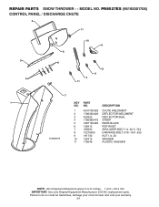
... THROWER - - MODEL NO. inches. 1 inch = 25.4 mm IMPORTANT: Use only Original Equipment Manufacturer (O.E.M.) replacement parts. NO. Failure to do so could be hazardous, damage your snow thrower and void your warranty. 24 DESCRIPTION 01.09.001-A 1 404770X428 CHUTE WELDMENT 2 178633X428 ... X .704 8 72270505 CARRIAGE BOLT 5/16−18 X .625 9 191730 NUT 1/4−20 10 155415 WASHER 11 179246 PLASTIC WASHER NOTE: All component dimensions given in U.S. PR8527ES (96192001706) CONTROL PANEL / DISCHARGE CHUTE 2 11 3 6 8 6 10 5 9 11 4 11 7 1 KEY...
... THROWER - - MODEL NO. inches. 1 inch = 25.4 mm IMPORTANT: Use only Original Equipment Manufacturer (O.E.M.) replacement parts. NO. Failure to do so could be hazardous, damage your snow thrower and void your warranty. 24 DESCRIPTION 01.09.001-A 1 404770X428 CHUTE WELDMENT 2 178633X428 ... X .704 8 72270505 CARRIAGE BOLT 5/16−18 X .625 9 191730 NUT 1/4−20 10 155415 WASHER 11 179246 PLASTIC WASHER NOTE: All component dimensions given in U.S. PR8527ES (96192001706) CONTROL PANEL / DISCHARGE CHUTE 2 11 3 6 8 6 10 5 9 11 4 11 7 1 KEY...
User Manual
Page 25
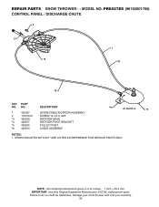
... *5 420675 *6 420674 DESCRIPTION LEVER/CABLE ROTATOR ASSEMBLY SCREW 10−24 X .625 ROTATOR HEAD ROTATOR PIVOT BRACKET PULLEY PIVOT CABLE ASSEMBLY *4 01.09.007-A *5 NOTES: 1. PR8527ES (96192001706) CONTROL PANEL / DISCHARGE CHUTE 2 2 *3 1 *6 *6 KEY PART NO. NOTE: All component dimensions given in U.S. inches. 1 inch = 25.4 mm IMPORTANT: Use only Original Equipment Manufacturer (O.E.M.) replacement...
... *5 420675 *6 420674 DESCRIPTION LEVER/CABLE ROTATOR ASSEMBLY SCREW 10−24 X .625 ROTATOR HEAD ROTATOR PIVOT BRACKET PULLEY PIVOT CABLE ASSEMBLY *4 01.09.007-A *5 NOTES: 1. PR8527ES (96192001706) CONTROL PANEL / DISCHARGE CHUTE 2 2 *3 1 *6 *6 KEY PART NO. NOTE: All component dimensions given in U.S. inches. 1 inch = 25.4 mm IMPORTANT: Use only Original Equipment Manufacturer (O.E.M.) replacement...
User Manual
Page 26
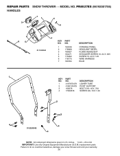
NO. REPAIR PARTS SNOW THROWER - - MODEL NO. PR8527ES (96192001706) HANDLES 3 2 71 4 5 6 5 4 KEY PART NO. Failure to do so could be hazardous, damage your snow thrower and void your warranty. 26 DESCRIPTION 1 419797X479 LOWER TUBE 2 418313X479 PIVOT SUPPORT 3 150078 ... 5 175262 6 178770 7 183784 DESCRIPTION CONSOLE PANEL HEADLIGHT BEZEL FLOOD HEADLIGHT SHOULDER SCREW 10−24 X .625 SCREW 10−24 X 1.25 WIRE HARNESS BULB 1 KEY PART NO. inches. 1 inch = 25.4 mm IMPORTANT: Use only Original Equipment Manufacturer (O.E.M.) replacement...
NO. REPAIR PARTS SNOW THROWER - - MODEL NO. PR8527ES (96192001706) HANDLES 3 2 71 4 5 6 5 4 KEY PART NO. Failure to do so could be hazardous, damage your snow thrower and void your warranty. 26 DESCRIPTION 1 419797X479 LOWER TUBE 2 418313X479 PIVOT SUPPORT 3 150078 ... 5 175262 6 178770 7 183784 DESCRIPTION CONSOLE PANEL HEADLIGHT BEZEL FLOOD HEADLIGHT SHOULDER SCREW 10−24 X .625 SCREW 10−24 X 1.25 WIRE HARNESS BULB 1 KEY PART NO. inches. 1 inch = 25.4 mm IMPORTANT: Use only Original Equipment Manufacturer (O.E.M.) replacement...


