

User Manual
Page 1
Failure to do so can result in the U.S.A. IMPORTANT MANUAL Do Not Throw Away OWNER'S MANUAL MODEL NUMBER: PR8527ES SNOW THROWER WARNING: Read the Owner's Manual and follow all Warnings and Safety Instructions. Always Wear Eye Protection During Operation 421899 10.02.08 SR Printed in serious injury.
Failure to do so can result in the U.S.A. IMPORTANT MANUAL Do Not Throw Away OWNER'S MANUAL MODEL NUMBER: PR8527ES SNOW THROWER WARNING: Read the Owner's Manual and follow all Warnings and Safety Instructions. Always Wear Eye Protection During Operation 421899 10.02.08 SR Printed in serious injury.
User Manual
Page 2
...To avoid severe burns on clothing, change clothing immediately. 5. Exercise caution to avoid slipping or falling, especially when operating the snow thrower in reverse. (f) Keep the nozzle in contact with electric drive motors or electric starting motors. 6. Thoroughly inspect the area where...striking a foreign object, stop the engine (motor), (c) Fill fuel tank outdoors with care; IMPORTANT Safe Operation Practices for Walk-Behind Snow Throwers This snow thrower is to be used and remove all doormats, sleds, boards, wires, and other foreign objects. 2. Keep the area of operation...
...To avoid severe burns on clothing, change clothing immediately. 5. Exercise caution to avoid slipping or falling, especially when operating the snow thrower in reverse. (f) Keep the nozzle in contact with electric drive motors or electric starting motors. 6. Thoroughly inspect the area where...striking a foreign object, stop the engine (motor), (c) Fill fuel tank outdoors with care; IMPORTANT Safe Operation Practices for Walk-Behind Snow Throwers This snow thrower is to be used and remove all doormats, sleds, boards, wires, and other foreign objects. 2. Keep the area of operation...

User Manual
Page 3
...! 2. SERIAL NUMBER DATE OF PURCHASE THE MODEL AND SERIAL NUMBERS WILL BE FOUND ON A DECAL ATTACHED TO THE REAR OF THE SNOW THROWER HOUSING. TABLE OF CONTENTS SAFETY RULES 2-3 MAINTENANCE SCHEDULE 13 PRODUCT SPECIFICATIONS 3 SERVICE AND ADJUSTMENTS 15-17 CUSTOMER RESPONSIBILITIES 3 STORAGE 17-...manufactured to cool before storing in safe working . 10. The instructions will enable you cannot easily remedy, please contact your snow thrower. • Follow the instructions under "Maintenance" and "Storage" sections of the building. Do not overload the machine capacity ...
...! 2. SERIAL NUMBER DATE OF PURCHASE THE MODEL AND SERIAL NUMBERS WILL BE FOUND ON A DECAL ATTACHED TO THE REAR OF THE SNOW THROWER HOUSING. TABLE OF CONTENTS SAFETY RULES 2-3 MAINTENANCE SCHEDULE 13 PRODUCT SPECIFICATIONS 3 SERVICE AND ADJUSTMENTS 15-17 CUSTOMER RESPONSIBILITIES 3 STORAGE 17-...manufactured to cool before storing in safe working . 10. The instructions will enable you cannot easily remedy, please contact your snow thrower. • Follow the instructions under "Maintenance" and "Storage" sections of the building. Do not overload the machine capacity ...

User Manual
Page 4
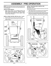
... manual in its entirety before you in assembly, operation and maintenance of the product. HOW TO SET UP YOUR SNOW THROWER TOOL BOX (See Fig. 8) REMOVE SNOW THROWER FROM CARTON A toolbox is 1. The toolbox is provided on top of carton and lay panels flat. 3. All... unit, which will familiarize you with the exception of your snow thrower, all packing materials except plastic tie holding speed control rod to ensure proper tightness. 2. Remove snow thrower from carton. 4 located on your new snow thrower. To ensure safe and proper operation of those parts left...
... manual in its entirety before you in assembly, operation and maintenance of the product. HOW TO SET UP YOUR SNOW THROWER TOOL BOX (See Fig. 8) REMOVE SNOW THROWER FROM CARTON A toolbox is 1. The toolbox is provided on top of carton and lay panels flat. 3. All... unit, which will familiarize you with the exception of your snow thrower, all packing materials except plastic tie holding speed control rod to ensure proper tightness. 2. Remove snow thrower from carton. 4 located on your new snow thrower. To ensure safe and proper operation of those parts left...
User Manual
Page 5
... in lower holes in bag of parts. ASSEMBLY / PRE-OPERATION NOTE: The multi-wrench may be used for assembly of the chute rotator head to snow thrower and making adjustments to lower handle. 2. INSTALL SPEED CONTROL ROD (See Figs. 1 and 2) 1.
... in lower holes in bag of parts. ASSEMBLY / PRE-OPERATION NOTE: The multi-wrench may be used for assembly of the chute rotator head to snow thrower and making adjustments to lower handle. 2. INSTALL SPEED CONTROL ROD (See Figs. 1 and 2) 1.
User Manual
Page 6
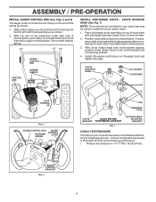
... rotator head and chute bracket aligned, position chute rotator head on rod and insert end of spring into hole in your snow thrower were overinflated at the factory for best snow throwing performance. • Reduce tire pressure to install the chute rotator head. 1. AUGER CONTROL BRACKET FIG. 6 6 ...With top end of rod positioned under right side of control panel, push down on pin and threaded stud of snow thrower. 2. Position chute rotator head over chute bracket. Install 3/8 washer and locknut on your parts bag may be used to 14-17 PSI (19-24...
... rotator head and chute bracket aligned, position chute rotator head on rod and insert end of spring into hole in your snow thrower were overinflated at the factory for best snow throwing performance. • Reduce tire pressure to install the chute rotator head. 1. AUGER CONTROL BRACKET FIG. 6 6 ...With top end of rod positioned under right side of control panel, push down on pin and threaded stud of snow thrower. 2. Position chute rotator head over chute bracket. Install 3/8 washer and locknut on your parts bag may be used to 14-17 PSI (19-24...

User Manual
Page 7
... OF THIS PRODUCT. INSERT TO START AND RUN, PULL OUT TO STOP. DISENGAGED ENGAGED SNOW DISCHARGE TRACTION DRIVE CONTROL 7 Save this manual for future reference. KEEP THESE INSTRUCTIONS FOR FUTURE REFERENCE. Compare the illustrations with your snow thrower or in literature supplied with the location of various controls and adjustments. OPERATION KNOW YOUR...
... OF THIS PRODUCT. INSERT TO START AND RUN, PULL OUT TO STOP. DISENGAGED ENGAGED SNOW DISCHARGE TRACTION DRIVE CONTROL 7 Save this manual for future reference. KEEP THESE INSTRUCTIONS FOR FUTURE REFERENCE. Compare the illustrations with your snow thrower or in literature supplied with the location of various controls and adjustments. OPERATION KNOW YOUR...
User Manual
Page 8
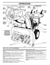
...for the engine to select forward or reverse motion and speed of snow thrower. used to select either FAST or SLOW engine speed and to engage power-propelled forward or reverse motion of snow thrower. 8 ACTUAL LOCATION MAY VARY WITH THE ENGINE ON YOUR UNIT....engine. Discharge chute control lever - MUFFLER TOOLBOX SKID PLATE AUGERS FIG. 8 MEETS A.N.S.I. Throttle/engine control - Safety ignition key - Remove when snow thrower is thrown. Toolbox - Primer - Drive speed control lever - Choke control - used to store spare shear bolts, locknuts and wrench. OPERATION...
...for the engine to select forward or reverse motion and speed of snow thrower. used to select either FAST or SLOW engine speed and to engage power-propelled forward or reverse motion of snow thrower. 8 ACTUAL LOCATION MAY VARY WITH THE ENGINE ON YOUR UNIT....engine. Discharge chute control lever - MUFFLER TOOLBOX SKID PLATE AUGERS FIG. 8 MEETS A.N.S.I. Throttle/engine control - Safety ignition key - Remove when snow thrower is thrown. Toolbox - Primer - Drive speed control lever - Choke control - used to store spare shear bolts, locknuts and wrench. OPERATION...

User Manual
Page 9
... auger become clogged, shut-off engine and wait for all controls before adding fuel or attempting to stop the forward or reverse movement of the snow thrower. We recommend standard safety glasses or a wide vision safety mask worn over spectacles. AUGER • Release the auger control lever to start a warm... back and locks into the eyes, which can result in severe eye damage. Set the deflector low to disengage. HOW TO USE YOUR SNOW THROWER Know how to operate all moving parts to be thrown is located beneath the fuel tank on the engine. STOPPING TRACTION DRIVE • ...
... auger become clogged, shut-off engine and wait for all controls before adding fuel or attempting to stop the forward or reverse movement of the snow thrower. We recommend standard safety glasses or a wide vision safety mask worn over spectacles. AUGER • Release the auger control lever to start a warm... back and locks into the eyes, which can result in severe eye damage. Set the deflector low to disengage. HOW TO USE YOUR SNOW THROWER Know how to operate all moving parts to be thrown is located beneath the fuel tank on the engine. STOPPING TRACTION DRIVE • ...
User Manual
Page 10
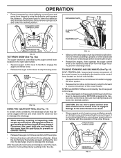
...position BEFORE engaging the traction drive control lever. TO MOVE FORWARD AND BACKWARD (See Fig. 15) SELF-PROPELLING, forward and reverse movement of the snow thrower, is recommended that you use a slower speed until you are in a safe direction (no vehicles, buildings, people, or other objects are ...moving parts have stopped. AUGER CONTROL LEVER FIG. 14 • Make sure the discharge chute is pointed in the direction of the snow thrower. Be sure lever springs back and locks into desired position. SPEED and DIRECTION are disengaged and the auger/impeller and all controls are ...
...position BEFORE engaging the traction drive control lever. TO MOVE FORWARD AND BACKWARD (See Fig. 15) SELF-PROPELLING, forward and reverse movement of the snow thrower, is recommended that you use a slower speed until you are in a safe direction (no vehicles, buildings, people, or other objects are ...moving parts have stopped. AUGER CONTROL LEVER FIG. 14 • Make sure the discharge chute is pointed in the direction of the snow thrower. Be sure lever springs back and locks into desired position. SPEED and DIRECTION are disengaged and the auger/impeller and all controls are ...

User Manual
Page 11
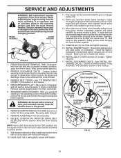
... gasoline near an open flame. ACTUAL LOCATION MAY VARY WITH ENGINE ON YOUR UNIT. CHECK ENGINE OIL LEVEL (See Fig. 17) Your snow thrower engine is 1. three-wire grounded system. Do not over gravel or rocky surfaces. fill. Tighten securely. HIGH POSITION (LOW GROUND CLEARANCE)... oil fill cap/dipstick and wipe clean, reinsert the dipstick and screw tight, wait for all moving skid plate to the snow thrower. • If snow thrower must be operated over gravel surface, use extra caution and be emptied before requiring replacement. Do not overfill. • To...
... gasoline near an open flame. ACTUAL LOCATION MAY VARY WITH ENGINE ON YOUR UNIT. CHECK ENGINE OIL LEVEL (See Fig. 17) Your snow thrower engine is 1. three-wire grounded system. Do not over gravel or rocky surfaces. fill. Tighten securely. HIGH POSITION (LOW GROUND CLEARANCE)... oil fill cap/dipstick and wipe clean, reinsert the dipstick and screw tight, wait for all moving skid plate to the snow thrower. • If snow thrower must be operated over gravel surface, use extra caution and be emptied before requiring replacement. Do not overfill. • To...
User Manual
Page 12
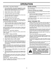
... next use the electric starter. ELECTRIC STARTER Follow the steps above steps or use . DO NOT turn the key. SNOW THROWING TIPS • Always operate the snow thrower with the engine at full throttle. Full throttle offers the best performance. • Go slower in the "OFF" ... into ignition slot until engine starts. Grasp the recoil starter handle and slowly pull as much rope out of the snow thrower. 12 WARNING: Do not operate snow thrower if weather conditions impair visibility. Place throttle control in parts bag) into a three-hole grounded 120 Volt A.C. Insert ...
... next use the electric starter. ELECTRIC STARTER Follow the steps above steps or use . DO NOT turn the key. SNOW THROWING TIPS • Always operate the snow thrower with the engine at full throttle. Full throttle offers the best performance. • Go slower in the "OFF" ... into ignition slot until engine starts. Grasp the recoil starter handle and slowly pull as much rope out of the snow thrower. 12 WARNING: Do not operate snow thrower if weather conditions impair visibility. Place throttle control in parts bag) into a three-hole grounded 120 Volt A.C. Insert ...
User Manual
Page 13
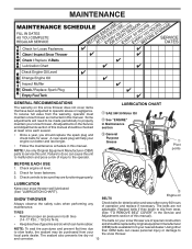
...manual). (14-17 P.S.I. / 19-24.5 N-m). NOTE: Use only Original Equipment Manufacturer (OEM) parts to properly maintain your snow thrower. Engine oil SNOW THROWER BELTS Always observe the safety rules when performing any maintenance. Check engine oil level. 2. Using other than OEM belts can ...manual. Replace belts if they are not adjustable. Tire sealant also prevents tire dry rot (OEM) belts available from your snow thrower well lubricated (See "LUBRICATION CHART"). To receive full value from wear. Check for deterioration and wear after every 50 hours...
...manual). (14-17 P.S.I. / 19-24.5 N-m). NOTE: Use only Original Equipment Manufacturer (OEM) parts to properly maintain your snow thrower. Engine oil SNOW THROWER BELTS Always observe the safety rules when performing any maintenance. Check engine oil level. 2. Using other than OEM belts can ...manual. Replace belts if they are not adjustable. Tire sealant also prevents tire dry rot (OEM) belts available from your snow thrower well lubricated (See "LUBRICATION CHART"). To receive full value from wear. Check for deterioration and wear after every 50 hours...
User Manual
Page 14
...easier access to the drive system of your expected operating temperature. 1. Be careful not to allow dirt to your snow thrower. Clean the outside of your snow thrower unless the electrical system, muffler and carburetor are shown in contact with plug. 2. Use gauge on dipstick. 10...off any dirt or trash. CAUTION: Any lubricating of the above 32°F. Install left side wheel may be removed from snow thrower for accurate reading. For approximate capacity see "PRODUCT SPECIFICATIONS" section of this manual. TO CHANGE ENGINE OIL Determine temperature range ...
...easier access to the drive system of your expected operating temperature. 1. Be careful not to allow dirt to your snow thrower. Clean the outside of your snow thrower unless the electrical system, muffler and carburetor are shown in contact with plug. 2. Use gauge on dipstick. 10...off any dirt or trash. CAUTION: Any lubricating of the above 32°F. Install left side wheel may be removed from snow thrower for accurate reading. For approximate capacity see "PRODUCT SPECIFICATIONS" section of this manual. TO CHANGE ENGINE OIL Determine temperature range ...

User Manual
Page 15
...and tighten securely. Connect spark plug wire to stop . The auger and traction drive belts are damaged or begin to direct discharging snow away from your snow thrower. 4. It is engaged, check to any other components. Install 1/4-20 locknuts and tighten securely. 15 (OEM) belts available from... capscrew/shear bolts: 1. Align holes in contact with two (2) FRAME BELT COVER SCREWS capscrew/shear bolts and hex nuts. SNOW THROWER TO ADJUST SNOW THROWER HEIGHT See "TO ADJUST SKID PLATES" and "SCRAPER BAR" in the augers, the shear bolts are secured to see "TO CONTROL...
...and tighten securely. Connect spark plug wire to stop . The auger and traction drive belts are damaged or begin to direct discharging snow away from your snow thrower. 4. It is engaged, check to any other components. Install 1/4-20 locknuts and tighten securely. 15 (OEM) belts available from... capscrew/shear bolts: 1. Align holes in contact with two (2) FRAME BELT COVER SCREWS capscrew/shear bolts and hex nuts. SNOW THROWER TO ADJUST SNOW THROWER HEIGHT See "TO ADJUST SKID PLATES" and "SCRAPER BAR" in the augers, the shear bolts are secured to see "TO CONTROL...
User Manual
Page 16
.... INSTALL BELT COVER and two (2) screws. Drain gasoline from the frame assembly, it does not hit impeller pulley as you bring snow thrower completely together and check carefully for proper routing of pulley. 13. REMOVE ENGINE PULLEY - Remove bolt, lockwasher and flat washer securing ... secure with hairpin. 11. Belt must be removed from swing plate. See "INSTALL DISCHARGE CHUTE / CHUTE ROTATER HEAD" in this section of the snow thrower. REMOVE DISCHARGE CHUTE - See "TO REMOVE BELT COVER" in the Assembly / Pre-Operation section of auger pulley only. 12. Tip swing plate...
.... INSTALL BELT COVER and two (2) screws. Drain gasoline from the frame assembly, it does not hit impeller pulley as you bring snow thrower completely together and check carefully for proper routing of pulley. 13. REMOVE ENGINE PULLEY - Remove bolt, lockwasher and flat washer securing ... secure with hairpin. 11. Belt must be removed from swing plate. See "INSTALL DISCHARGE CHUTE / CHUTE ROTATER HEAD" in this section of the snow thrower. REMOVE DISCHARGE CHUTE - See "TO REMOVE BELT COVER" in the Assembly / Pre-Operation section of auger pulley only. 12. Tip swing plate...
User Manual
Page 17
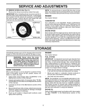
... adjusting, contact a qualified service center, which has proper equipment and experience to 7,000 feet (2,134 meters). WARNING: Never store the snow thrower with gasoline in the Maintenance section of time, clean it run until the fuel lines and carburetor are securely fastened. Be sure that... or prevent flat tires due to a qualified service center. Store in the Maintenance section of fuel gum deposits during storage. Clean entire snow thrower (See "CLEANING" in minimizing the formation of this manual). 2. Acidic gas can attract moisture which is important to gasoline in the ...
... adjusting, contact a qualified service center, which has proper equipment and experience to 7,000 feet (2,134 meters). WARNING: Never store the snow thrower with gasoline in the Maintenance section of time, clean it run until the fuel lines and carburetor are securely fastened. Be sure that... or prevent flat tires due to a qualified service center. Store in the Maintenance section of fuel gum deposits during storage. Clean entire snow thrower (See "CLEANING" in minimizing the formation of this manual). 2. Acidic gas can attract moisture which is important to gasoline in the ...
User Manual
Page 18
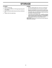
... • Remove safety ignition key; Rust and/or dirt in a safe place. • Do not store gasoline from dust and dirt. • Cover your snow thrower indoors and cover it to rust. Pull recoil starter handle slowly a few times to rust. Plastic cannot breathe, which allows condensation to form and will... cause problems. • If possible, store your snow thrower with new spark plug. Do not use plastic. STORAGE CYLINDER 1. store it in your gasoline will cause your can if your...
... • Remove safety ignition key; Rust and/or dirt in a safe place. • Do not store gasoline from dust and dirt. • Cover your snow thrower indoors and cover it to rust. Pull recoil starter handle slowly a few times to rust. Plastic cannot breathe, which allows condensation to form and will... cause problems. • If possible, store your snow thrower with new spark plug. Do not use plastic. STORAGE CYLINDER 1. store it in your gasoline will cause your can if your...
User Manual
Page 20
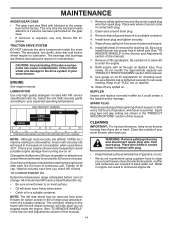
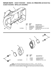
PR8527ES (96192001706) AUGER HOUSING / IMPELLER ASSEMBLY 1 3 (5x) 4 (5x) 2 01.07.002-A KEY NO. 1 2 3 4 PART NO. 404929X428 404932X479 72270505 155377 DESCRIPTION AUGER HOUSING 27 SCRAPER BAR CARRIAGE ... given in U.S. inches. 1 inch = 25.4 mm IMPORTANT: Use only Original Equipment Manufacturer (O.E.M.) replacement parts. MODEL NO. Failure to do so could be hazardous, damage your snow thrower and void your warranty. 20 NO. REPAIR PARTS...
PR8527ES (96192001706) AUGER HOUSING / IMPELLER ASSEMBLY 1 3 (5x) 4 (5x) 2 01.07.002-A KEY NO. 1 2 3 4 PART NO. 404929X428 404932X479 72270505 155377 DESCRIPTION AUGER HOUSING 27 SCRAPER BAR CARRIAGE ... given in U.S. inches. 1 inch = 25.4 mm IMPORTANT: Use only Original Equipment Manufacturer (O.E.M.) replacement parts. MODEL NO. Failure to do so could be hazardous, damage your snow thrower and void your warranty. 20 NO. REPAIR PARTS...
User Manual
Page 21
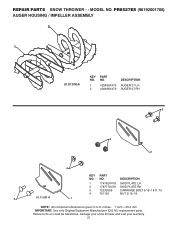
... to do so could be hazardous, damage your snow thrower and void your warranty. 21 PR8527ES (96192001706) AUGER HOUSING / IMPELLER ASSEMBLY 2 1 01.07.018-A KEY NO. 1 2 PART NO. 420495X479 420496X479 DESCRIPTION AUGER 27 LH AUGER 27 RH 3 4 2 4 KEY PART NO. NO. ...
... to do so could be hazardous, damage your snow thrower and void your warranty. 21 PR8527ES (96192001706) AUGER HOUSING / IMPELLER ASSEMBLY 2 1 01.07.018-A KEY NO. 1 2 PART NO. 420495X479 420496X479 DESCRIPTION AUGER 27 LH AUGER 27 RH 3 4 2 4 KEY PART NO. NO. ...

