
User Manual
Page 2
...• Read,understand,andfollowallinstructionsinthemanual and on it, do not mow it at anyone enters the area. The mower could expose moving parts or allow children to cool before operating or storing the - edge of grass, leaves, or other people before dismounting. Reduced ...rocks, tree limbs, etc. • Watch for wheel weights or counterweights to improve stability. • Use extra care with manufacturer's recommended parts, when necessary. • Mower blades are often attracted to plow leaves running machine unattended. Do not operate the mower without either the ...
...• Read,understand,andfollowallinstructionsinthemanual and on it, do not mow it at anyone enters the area. The mower could expose moving parts or allow children to cool before operating or storing the - edge of grass, leaves, or other people before dismounting. Reduced ...rocks, tree limbs, etc. • Watch for wheel weights or counterweights to improve stability. • Use extra care with manufacturer's recommended parts, when necessary. • Mower blades are often attracted to plow leaves running machine unattended. Do not operate the mower without either the ...
User Manual
Page 3
... your tractor. TABLE OF CONTENTS SAFETY RULES 2-3 SERVICE AND ADJUSTMENTS 19-23 PRODUCT SPECIFICATIONS 4 STORAGE 24 CUSTOMER RESPONSIBILITIES 4, 15-18 TROUBLESHOOTING 25-26 ASSEMBLY 6-8 REPAIR PARTS 28-43 OPERATION 9-14 WARRANTY 46 MAINTENANCE SCHEDULE 15 3 SAFETY RULES Safe Operation Practices for Ride-On Mowers • Be sure the area is dangerous...
... your tractor. TABLE OF CONTENTS SAFETY RULES 2-3 SERVICE AND ADJUSTMENTS 19-23 PRODUCT SPECIFICATIONS 4 STORAGE 24 CUSTOMER RESPONSIBILITIES 4, 15-18 TROUBLESHOOTING 25-26 ASSEMBLY 6-8 REPAIR PARTS 28-43 OPERATION 9-14 WARRANTY 46 MAINTENANCE SCHEDULE 15 3 SAFETY RULES Safe Operation Practices for Ride-On Mowers • Be sure the area is dangerous...
User Manual
Page 4
... easily remedy, please contact your tractor. • Follow the instructions under "Customer Responsibili- Federal laws apply on your nearest authorized service center/department (See REPAIR PARTS section of this tractor. LBS. CONGRATULATIONS on federal lands. 4 The instructions will enable you the best possible dependability and performance. ties" and "Storage" sections of...
... easily remedy, please contact your tractor. • Follow the instructions under "Customer Responsibili- Federal laws apply on your nearest authorized service center/department (See REPAIR PARTS section of this tractor. LBS. CONGRATULATIONS on federal lands. 4 The instructions will enable you the best possible dependability and performance. ties" and "Storage" sections of...
User Manual
Page 6
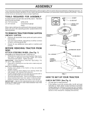
...large flat washer, 1/2 hex nut and tighten securely. • Snap steering wheel insert into service after month and year indicated on all parts and hardware you are in the operating position (seated behind the steering wheel). INSERT 1/2 HEX NUT LARGE FLAT WASHER TO REMOVE TRACTOR FROM ...CARTON UNPACK CARTON • Remove all accessible loose parts and parts cartons from carton. • Cut, from steering wheel and slide adapter onto steering shaft extension. • Position steering wheel so cross ...
...large flat washer, 1/2 hex nut and tighten securely. • Snap steering wheel insert into service after month and year indicated on all parts and hardware you are in the operating position (seated behind the steering wheel). INSERT 1/2 HEX NUT LARGE FLAT WASHER TO REMOVE TRACTOR FROM ...CARTON UNPACK CARTON • Remove all accessible loose parts and parts cartons from carton. • Cut, from steering wheel and slide adapter onto steering shaft extension. • Position steering wheel so cross ...
User Manual
Page 8
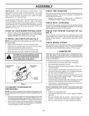
... MOWER HOUSING" in "PRODUCT SPECIFICATIONS" section of mower deck. PLEASE REVIEW THE FOLLOWING CHECKLIST: ✓ All assembly instructions have been completed. ✓ No remaining loose parts in upright position. • Place front of mulcher plate over front of mower deck opening and slide into place, as shown. • Hook front latch...
... MOWER HOUSING" in "PRODUCT SPECIFICATIONS" section of mower deck. PLEASE REVIEW THE FOLLOWING CHECKLIST: ✓ All assembly instructions have been completed. ✓ No remaining loose parts in upright position. • Place front of mulcher plate over front of mower deck opening and slide into place, as shown. • Hook front latch...
User Manual
Page 16
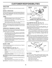
... adjusted. (See "TO ADJUST BRAKE" in all tires (See "PRODUCT SPECIFICATIONS" section of gasoline, oil, or insect control chemicals which is balanced. If your local parts dealer. Replace bent or damaged blades. IMPORTANT: BLADE BOLT IS GRADE 8 HEAT TREATED. FIG. 11 TO SHARPEN BLADE (See Fig. 12) NOTE: We do , be...
... adjusted. (See "TO ADJUST BRAKE" in all tires (See "PRODUCT SPECIFICATIONS" section of gasoline, oil, or insect control chemicals which is balanced. If your local parts dealer. Replace bent or damaged blades. IMPORTANT: BLADE BOLT IS GRADE 8 HEAT TREATED. FIG. 11 TO SHARPEN BLADE (See Fig. 12) NOTE: We do , be...
User Manual
Page 19
... THE MOWER DECK IS TO BE MOUNTED ON THE TRACTOR, REMOVE THE FRONT LINKS AND HOOK THE CLUTCH SPRING INTO SQUARE HOLE IN FRAME. moving parts have completely stopped. • Disconnect spark plug wire from deck by re- TO INSTALL MOWER (See Fig. 16) • Raise attachment lift lever to its...
... THE MOWER DECK IS TO BE MOUNTED ON THE TRACTOR, REMOVE THE FRONT LINKS AND HOOK THE CLUTCH SPRING INTO SQUARE HOLE IN FRAME. moving parts have completely stopped. • Disconnect spark plug wire from deck by re- TO INSTALL MOWER (See Fig. 16) • Raise attachment lift lever to its...
User Manual
Page 22
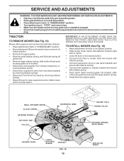
... lose). • Repair tire and reassemble. • On rear wheels only: align grooves in axle groove. • Replace axle cover. SEAT PAN If your local parts dealer. Keep sparks, flame and smoking materials away from tractor. • Install new battery with terminals in same position as shown. Before connecting battery, remove...
... lose). • Repair tire and reassemble. • On rear wheels only: align grooves in axle groove. • Replace axle cover. SEAT PAN If your local parts dealer. Keep sparks, flame and smoking materials away from tractor. • Install new battery with terminals in same position as shown. Before connecting battery, remove...
User Manual
Page 23
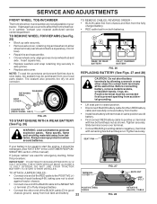
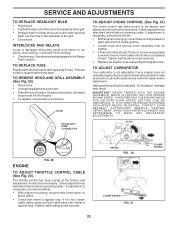
... before loosening cable. High speed stop . See electrical wiring diagram in fuse. TO REPLACE FUSE Replace with 20 amp automotive-type plug-in the Repair Parts section. HOOD HEADLIGHT WIRE CONNECTOR TO ADJUST CHOKE CONTROL (See Fig. 31) The choke control has been preset at the factory and adjustment should not...
... before loosening cable. High speed stop . See electrical wiring diagram in fuse. TO REPLACE FUSE Replace with 20 amp automotive-type plug-in the Repair Parts section. HOOD HEADLIGHT WIRE CONNECTOR TO ADJUST CHOKE CONTROL (See Fig. 31) The choke control has been preset at the factory and adjustment should not...
User Manual
Page 24
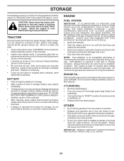
... found on concrete or damp surfaces. ENGINE FUEL SYSTEM IMPORTANT: IT IS IMPORTANT TO PREVENT GUM DEPOSITS FROM FORMING IN ESSENTIAL FUEL SYSTEM PARTS SUCH AS CARBURETOR, FUEL FILTER, FUEL HOSE, OR TANK DURING STORAGE. OTHER • Do not store gasoline from tractor for storage,...FORMATION OF ACIDS DURING STORAGE. Do not use engine or carburetor cleaner products in storage, battery may reach an open flame or spark. Inspect moving parts for winter storage. BATTERY • Fully charge the battery for storage. • After a period of this manual). • Inspect and ...
... found on concrete or damp surfaces. ENGINE FUEL SYSTEM IMPORTANT: IT IS IMPORTANT TO PREVENT GUM DEPOSITS FROM FORMING IN ESSENTIAL FUEL SYSTEM PARTS SUCH AS CARBURETOR, FUEL FILTER, FUEL HOSE, OR TANK DURING STORAGE. OTHER • Do not store gasoline from tractor for storage,...FORMATION OF ACIDS DURING STORAGE. Do not use engine or carburetor cleaner products in storage, battery may reach an open flame or spark. Inspect moving parts for winter storage. BATTERY • Fully charge the battery for storage. • After a period of this manual). • Inspect and ...
User Manual
Page 25
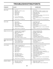
...Check oil level/change spark plug. 7. Connect and tighten spark plug wire. 11. Worn, bent or loose blade. 2. Tighten loose part(s). Engine flooded. 4. Loose or damaged wiring. 9. Check all wiring. 7. Hard to start 1. Carburetor out of adjustment. 10. ...10. Faulty operator presence switch(es). 1. Check/replace solenoid or starter. Engine will not start 1. Faulty ignition switch. 8. Loose/damaged part(s). 1. Corroded battery terminals. 3. Engine valves out of power 1. Stale or dirty fuel. 6. Loose or damaged wiring. 7. Replace spark...
...Check oil level/change spark plug. 7. Connect and tighten spark plug wire. 11. Worn, bent or loose blade. 2. Tighten loose part(s). Engine flooded. 4. Loose or damaged wiring. 9. Check all wiring. 7. Hard to start 1. Carburetor out of adjustment. 10. ...10. Faulty operator presence switch(es). 1. Check/replace solenoid or starter. Engine will not start 1. Faulty ignition switch. 8. Loose/damaged part(s). 1. Corroded battery terminals. 3. Engine valves out of power 1. Stale or dirty fuel. 6. Loose or damaged wiring. 7. Replace spark...
User Manual
Page 29
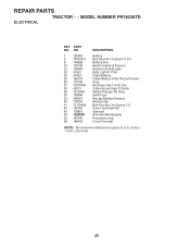
REPAIR PARTS TRACTOR - - NO. 1 163465 2 74760412 8 176689 16 176138 21 175685 22 4152J 24 4799J 25 146147 26 175158 27 73510400 28 4207J 29 121305X 30 175566 ... Hex 1/4-20uncx 1/2 Cover Terminal Red Solenoid Ammeter Rectangular Protection Loop Cover Terminal NOTE: All component dimensions given in U.S. inches 1 inch = 25.4 mm 29 MODEL NUMBER PR1842STD ELECTRICAL KEY PART NO.
REPAIR PARTS TRACTOR - - NO. 1 163465 2 74760412 8 176689 16 176138 21 175685 22 4152J 24 4799J 25 146147 26 175158 27 73510400 28 4207J 29 121305X 30 175566 ... Hex 1/4-20uncx 1/2 Cover Terminal Red Solenoid Ammeter Rectangular Protection Loop Cover Terminal NOTE: All component dimensions given in U.S. inches 1 inch = 25.4 mm 29 MODEL NUMBER PR1842STD ELECTRICAL KEY PART NO.
User Manual
Page 31
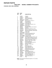
MODEL NUMBER PR1842STD CHASSIS AND ENCLOSURES KEY PART NO. NO. inches 1 inch = 25.4 mm 31 DESCRIPTION 1 174619 Chassis 2 176554 Drawbar 3 17060612 Screw 3/8-16x.75 5 155272 Bumper Hood/Dash 9 168337X012 Dash P/L 10 72140608 Bolt ... 145212 Nut Hex Flange Lock 212 156229 Insert Lens Reflect P/L LT 219 17000512 Screw 5/16-18 x 3/4 - - 5479J Plug NOTE: All component dimensions given in U.S. REPAIR PARTS TRACTOR - -
MODEL NUMBER PR1842STD CHASSIS AND ENCLOSURES KEY PART NO. NO. inches 1 inch = 25.4 mm 31 DESCRIPTION 1 174619 Chassis 2 176554 Drawbar 3 17060612 Screw 3/8-16x.75 5 155272 Bumper Hood/Dash 9 168337X012 Dash P/L 10 72140608 Bolt ... 145212 Nut Hex Flange Lock 212 156229 Insert Lens Reflect P/L LT 219 17000512 Screw 5/16-18 x 3/4 - - 5479J Plug NOTE: All component dimensions given in U.S. REPAIR PARTS TRACTOR - -
User Manual
Page 33
REPAIR PARTS TRACTOR - - MODEL NUMBER PR1842STD DRIVE KEY PART NO. inches 1 inch = 25.4 mm 33 DESCRIPTION 63 175410 Engine Pulley 64 71170764 Bolt Hex 65 10040700 Washer ... 73680600 52 73680500 53 105710X 55 105709X 56 17060620 57 130801 59 169691 61 17120614 62 8883R DESCRIPTION Transaxle Peerless (206-545C) (Order parts from transaxle manufacturer) Spring Return Brake T/a Zinc Pulley Transaxle 18" tires Ring Retainer # 5100-62 Strap Torque 30 Degrees Screw 5/16... 3/8-16 x 1-1/4 V-Belt Ground Drive 95 25 Keeper Belt Span Ctr Screw 3/8-16 x .875 Cover Pedal Blk Round KEY PART NO.
REPAIR PARTS TRACTOR - - MODEL NUMBER PR1842STD DRIVE KEY PART NO. inches 1 inch = 25.4 mm 33 DESCRIPTION 63 175410 Engine Pulley 64 71170764 Bolt Hex 65 10040700 Washer ... 73680600 52 73680500 53 105710X 55 105709X 56 17060620 57 130801 59 169691 61 17120614 62 8883R DESCRIPTION Transaxle Peerless (206-545C) (Order parts from transaxle manufacturer) Spring Return Brake T/a Zinc Pulley Transaxle 18" tires Ring Retainer # 5100-62 Strap Torque 30 Degrees Screw 5/16... 3/8-16 x 1-1/4 V-Belt Ground Drive 95 25 Keeper Belt Span Ctr Screw 3/8-16 x .875 Cover Pedal Blk Round KEY PART NO.

User Manual
Page 34
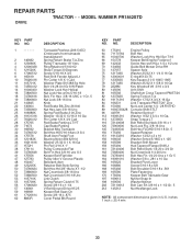
MODEL NUMBER PR1842STD STEERING ASSEMBLY 38 12 39 1 37 44 51 91 43 41 42 37 36 54 88 71 29 17 68 29 15 15 15 82 29 46 8 6 2 87 5 68 67 13 65 46 8 6 67 67 3 32 11 40 33 34 10 35 87 5 4 43 43 6 8 34 REPAIR PARTS TRACTOR - -
MODEL NUMBER PR1842STD STEERING ASSEMBLY 38 12 39 1 37 44 51 91 43 41 42 37 36 54 88 71 29 17 68 29 15 15 15 82 29 46 8 6 2 87 5 68 67 13 65 46 8 6 67 67 3 32 11 40 33 34 10 35 87 5 4 43 43 6 8 34 REPAIR PARTS TRACTOR - -

User Manual
Page 35
NO. inches 1 inch = 25.4 mm 35 MODEL NUMBER PR1842STD STEERING ASSEMBLY KEY PART NO. Axle Front 15 145212 Nut Hex Flange Lock 17 180641 Shaft Asm. Steering 29 17060612 Screw 3/8-16x.75 32 171888 Rod Tie 33 19111216 ...-75 10 175121 Link Drag 11 10040600 Washer Lock Hvy Hlcl Spr 3/8 12 73940800 Nut Hex Jam Toplock 1/2-20 UNF 13 136518 Spacer Brg. REPAIR PARTS TRACTOR - -
NO. inches 1 inch = 25.4 mm 35 MODEL NUMBER PR1842STD STEERING ASSEMBLY KEY PART NO. Axle Front 15 145212 Nut Hex Flange Lock 17 180641 Shaft Asm. Steering 29 17060612 Screw 3/8-16x.75 32 171888 Rod Tie 33 19111216 ...-75 10 175121 Link Drag 11 10040600 Washer Lock Hvy Hlcl Spr 3/8 12 73940800 Nut Hex Jam Toplock 1/2-20 UNF 13 136518 Spacer Brg. REPAIR PARTS TRACTOR - -

User Manual
Page 36
... 13/32 X 1 X 14 Ga. Bolt Shoulder 5/16-18 X 62 NOTE: All component dimensions given in U.S. REPAIR PARTS TRACTOR - - MODEL NUMBER PR1842STD SEAT ASSEMBLY 1 14 24 8 9 7 10 5 8 9 7 2 5 6 22 21 16 25 15 11 4 13 17 12 3 KEY PART NO. DESCRIPTION 12 121246X 13 121248X 14 72050412 15 134300 16 121250X 17 123976X 21 171852... Flg Gr 5 Zinc Bolt Shoulder 5/16-18 Unc Nut Hex Lock W/Ins 5/16-18 Washer 17/32 X 1-3/16 X 12 Ga. Pan Seat Knob Seat KEY PART NO.
... 13/32 X 1 X 14 Ga. Bolt Shoulder 5/16-18 X 62 NOTE: All component dimensions given in U.S. REPAIR PARTS TRACTOR - - MODEL NUMBER PR1842STD SEAT ASSEMBLY 1 14 24 8 9 7 10 5 8 9 7 2 5 6 22 21 16 25 15 11 4 13 17 12 3 KEY PART NO. DESCRIPTION 12 121246X 13 121248X 14 72050412 15 134300 16 121250X 17 123976X 21 171852... Flg Gr 5 Zinc Bolt Shoulder 5/16-18 Unc Nut Hex Lock W/Ins 5/16-18 Washer 17/32 X 1-3/16 X 12 Ga. Pan Seat Knob Seat KEY PART NO.

User Manual
Page 37
... Bat Dan/Psn Pad Footrest LH Pad Footrest RH Decal Handle Lft Height Adjust Manual Owner's (English) Manual Owner's (French) WHEELS AND TIRES 1 2 5,8 4,10 7 6 KEY PART NO. Tube) NOTE: All component dimensions given in U.S. inches 1 inch = 25.4 mm 37 NO. 1 156369 2 176305 3 176308 4 182005 5 183742 6 179128 8 170563 9 172740 10 157140 11... 9 170456 Tire R Ts 20x10-8 C Service 10 7152J Tube Rear (Service Item Only) 11 104757X421 Cap Axle 1 50 X 1 00 - - 144334 Sealant, Tire ( 10 oz. MODEL NUMBER PR1842STD DECALS 2 11 16 4 3 4 10 2 20 9 1 86 18 5 14 19 KEY...
... Bat Dan/Psn Pad Footrest LH Pad Footrest RH Decal Handle Lft Height Adjust Manual Owner's (English) Manual Owner's (French) WHEELS AND TIRES 1 2 5,8 4,10 7 6 KEY PART NO. Tube) NOTE: All component dimensions given in U.S. inches 1 inch = 25.4 mm 37 NO. 1 156369 2 176305 3 176308 4 182005 5 183742 6 179128 8 170563 9 172740 10 157140 11... 9 170456 Tire R Ts 20x10-8 C Service 10 7152J Tube Rear (Service Item Only) 11 104757X421 Cap Axle 1 50 X 1 00 - - 144334 Sealant, Tire ( 10 oz. MODEL NUMBER PR1842STD DECALS 2 11 16 4 3 4 10 2 20 9 1 86 18 5 14 19 KEY...
User Manual
Page 39
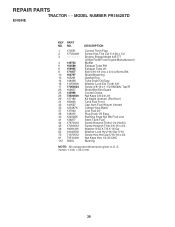
inches 1 inch = 25.4 mm 39 REPAIR PARTS TRACTOR - - NO. 1 170551 2 17720408 3 -------- 4 149723 5 160589 6 159955 8 171877 10 162797 13 165291 14 148456 16 11050600 17 ... 72 71070512 81 73510400 112 3645J DESCRIPTION Control Th/ch Flag Screw Hex Thd Cut 1/4-20 x 1/2 Engine, Briggs Model 445777 (Order Parts From Engine Manufacturer) Muffler Exhaust Tube RH Exhaust Tube LH Bolt 5/16-18 Unc x 3/4 w/Sems Blk Shield Browning Gasket Eng Tube ... Hd Cap 5/16-18 x 3/4 Nut Keps Hex 1/4-20 UNC Bushing NOTE: All component dimensions given in U. S. MODEL NUMBER PR1842STD ENGINE KEY PART NO.
inches 1 inch = 25.4 mm 39 REPAIR PARTS TRACTOR - - NO. 1 170551 2 17720408 3 -------- 4 149723 5 160589 6 159955 8 171877 10 162797 13 165291 14 148456 16 11050600 17 ... 72 71070512 81 73510400 112 3645J DESCRIPTION Control Th/ch Flag Screw Hex Thd Cut 1/4-20 x 1/2 Engine, Briggs Model 445777 (Order Parts From Engine Manufacturer) Muffler Exhaust Tube RH Exhaust Tube LH Bolt 5/16-18 Unc x 3/4 w/Sems Blk Shield Browning Gasket Eng Tube ... Hd Cap 5/16-18 x 3/4 Nut Keps Hex 1/4-20 UNC Bushing NOTE: All component dimensions given in U. S. MODEL NUMBER PR1842STD ENGINE KEY PART NO.

User Manual
Page 41
..., Brake 54 133943 Washer, Hardened 55 155046 Arm, Idler 56 122052X Spacer, Retainer 59 173442 Guard TUV Idler 67 171598 Knob KEY PART NO. NO. MODEL NUMBER PR1842STD MOWER DECK KEY PART NO. DESCRIPTION 68 144959 V-Belt, 42" Mower 91 180532 Bracket Asm. inches 1 inch = 25.4 mm 41 Noseroller LH 94 132264 Roller... - - 130794 Mandrel Assembly (Includes Housing, Shaft and Shaft Hardware Only-Pulley Not Included) - - 172559 Replacement Mower, Complete NOTE: All component dimensions given in U.S. NO. REPAIR PARTS TRACTOR - -
..., Brake 54 133943 Washer, Hardened 55 155046 Arm, Idler 56 122052X Spacer, Retainer 59 173442 Guard TUV Idler 67 171598 Knob KEY PART NO. NO. MODEL NUMBER PR1842STD MOWER DECK KEY PART NO. DESCRIPTION 68 144959 V-Belt, 42" Mower 91 180532 Bracket Asm. inches 1 inch = 25.4 mm 41 Noseroller LH 94 132264 Roller... - - 130794 Mandrel Assembly (Includes Housing, Shaft and Shaft Hardware Only-Pulley Not Included) - - 172559 Replacement Mower, Complete NOTE: All component dimensions given in U.S. NO. REPAIR PARTS TRACTOR - -


