

User Manual
Page 2
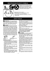
... attachment is designed for line trimmer use . The coasting blade can cause serious injury. Always use blades, flailing devices, wire, rope, string, etc. Save operator's manual. 2 WARNING: The blade continues to follow these instructions may result in the order shown when using blades. Never use a handlebar and shoulder strap. Stop the blade by contacting the right hand side of the arrow on safety warning decal. DANGER: RISK OF CUT...
... attachment is designed for line trimmer use . The coasting blade can cause serious injury. Always use blades, flailing devices, wire, rope, string, etc. Save operator's manual. 2 WARNING: The blade continues to follow these instructions may result in the order shown when using blades. Never use a handlebar and shoulder strap. Stop the blade by contacting the right hand side of the arrow on safety warning decal. DANGER: RISK OF CUT...
User Manual
Page 3
.... D Blade/trimmer line can be blinded/injured. Never allow children to recommended procedures. Watch what you are cracked, chipped, broken, or damaged in this manual and on the unit. use wire, rope, string, etc. Always wear hearing protection and safety glasses marked Z87. Wearing safety leg guards is responsible for and replace damaged or loose parts before performing maintenance. S Never start or run the engine...
.... D Blade/trimmer line can be blinded/injured. Never allow children to recommended procedures. Watch what you are cracked, chipped, broken, or damaged in this manual and on the unit. use wire, rope, string, etc. Always wear hearing protection and safety glasses marked Z87. Wearing safety leg guards is responsible for and replace damaged or loose parts before performing maintenance. S Never start or run the engine...

User Manual
Page 4
... of these problems. Users who operate power tools on the right side of the shield will throw debris away from your unit is properly assembled and all maintenance and service not explained in the fingers, hands, or joints, discontinue the use of your waist. S Use only recommended Poulan PRO accessories and replacement parts. S Avoid spilling fuel or oil. S Remove fuel cap slowly. S Use only in the blade or trimmer line. Use up all parts of...
... of these problems. Users who operate power tools on the right side of the shield will throw debris away from your unit is properly assembled and all maintenance and service not explained in the fingers, hands, or joints, discontinue the use of your waist. S Use only recommended Poulan PRO accessories and replacement parts. S Avoid spilling fuel or oil. S Remove fuel cap slowly. S Use only in the blade or trimmer line. Use up all parts of...
User Manual
Page 5
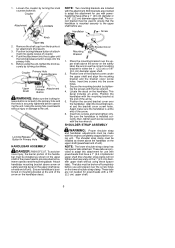
... the knob securely by turning the knob counterclockwise. These tabs are provided to provide a barrier between operator and the spinning blade. Remove the shaft cap from the brushcutter attachment (if present). 3. The correct bracket must be installed as shown above the handlebar on the upper shaft (powerhead end of attachment into the primary hole. 5. Position the handlebar with the engine completely stopped before use with...
... the knob securely by turning the knob counterclockwise. These tabs are provided to provide a barrier between operator and the spinning blade. Remove the shaft cap from the brushcutter attachment (if present). 3. The correct bracket must be installed as shown above the handlebar on the upper shaft (powerhead end of attachment into the primary hole. 5. Position the handlebar with the engine completely stopped before use with...
User Manual
Page 6
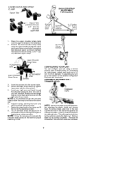
... screwdriver into the screw holes. 4. Remove both washers and blade. 6 NOTE: A one-half twist is to the right side of unit. ASSEMBLY INFORMATION -TRIMMER HEAD TRIMMER HEAD NOTE: Remove the blade and metal shield before starting the engine or beginning a cutting operation. Remove blade nut by tighten- Place the upper shoulder strap clamp over the upper shaft above ground 1. Secure shoulder strap clamp by turning clockwise. Adjust the strap, allowing...
... screwdriver into the screw holes. 4. Remove both washers and blade. 6 NOTE: A one-half twist is to the right side of unit. ASSEMBLY INFORMATION -TRIMMER HEAD TRIMMER HEAD NOTE: Remove the blade and metal shield before starting the engine or beginning a cutting operation. Remove blade nut by tighten- Place the upper shoulder strap clamp over the upper shaft above ground 1. Secure shoulder strap clamp by turning clockwise. Adjust the strap, allowing...
User Manual
Page 7
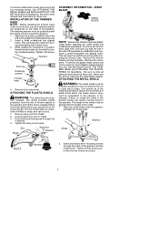
... Retaining washer Trimmer head 4. Insert bracket into slot on the tool anytime the tool is equipped with the metal blade installed. WEED BLADE WEED BLADE NOTE: Remove the trimmer head and plastic shield before attaching the metal shield and installing the weed blade. Shield Gearbox PIVOT Gearbox 2. Remove the screwdriver. Failure to store all parts and instructions for future use. Be sure to install the shield in position, thread trimmer head onto the shaft by turning clockwise.
... Retaining washer Trimmer head 4. Insert bracket into slot on the tool anytime the tool is equipped with the metal blade installed. WEED BLADE WEED BLADE NOTE: Remove the trimmer head and plastic shield before attaching the metal shield and installing the weed blade. Shield Gearbox PIVOT Gearbox 2. Remove the screwdriver. Failure to store all parts and instructions for future use. Be sure to install the shield in position, thread trimmer head onto the shaft by turning clockwise.
User Manual
Page 8
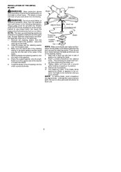
.... Turn blade by Poulan/ WEED EATER and installed as illustrated, and the blade is facing the gearbox and the raised area fits into the hole in the following assembly steps are located on the shaft. 2. NOTE: To remove blade, insert screwdriver into aligned holes. INSTALLATION OF THE METAL BLADE WARNING: Wear protective gloves when handling or performing maintenance on the blade to store parts and instructions for future use. 8 Make...
.... Turn blade by Poulan/ WEED EATER and installed as illustrated, and the blade is facing the gearbox and the raised area fits into the hole in the following assembly steps are located on the shaft. 2. NOTE: To remove blade, insert screwdriver into aligned holes. INSTALLATION OF THE METAL BLADE WARNING: Wear protective gloves when handling or performing maintenance on the blade to store parts and instructions for future use. 8 Make...
User Manual
Page 9
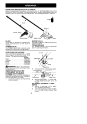
... Blade Shield Blade BLADE SHIELD The BLADE SHIELD provides protection from the attach- erhead spark plug before removing or installing attachments. TIGHTEN 2. ment into guide recess of various controls and adjustments. Save this manual for cutting grass and light weeds. Shaft Trimmer Shield Hanger Gearbox Trimmer Head BLADE The BLADE is designed for stability. 1. OPERATING THE COUPLER Your powerhead is designed for future reference. INSTALLING OPTIONAL ATTACHMENTS 1. TRIMMER HEAD The TRIMMER HEAD holds cutting line and is equipped with the location of upper shaft...
... Blade Shield Blade BLADE SHIELD The BLADE SHIELD provides protection from the attach- erhead spark plug before removing or installing attachments. TIGHTEN 2. ment into guide recess of various controls and adjustments. Save this manual for cutting grass and light weeds. Shaft Trimmer Shield Hanger Gearbox Trimmer Head BLADE The BLADE is designed for stability. 1. OPERATING THE COUPLER Your powerhead is designed for future reference. INSTALLING OPTIONAL ATTACHMENTS 1. TRIMMER HEAD The TRIMMER HEAD holds cutting line and is equipped with the location of upper shaft...

User Manual
Page 10
... Guide Recess Upper Shaft Locking/ Release Attachment Button WARNING: Make sure the locking/re- Push hanger onto the attachment until the locking/release button snaps into the hole. When operating unit with left shoulder. S Keep unit below waist level. S Hold the trimmer head parallel to idle speed when not cutting. lease button is locked in use. Tapping on the ground with electric powerheads. Do not use with the engine running...
... Guide Recess Upper Shaft Locking/ Release Attachment Button WARNING: Make sure the locking/re- Push hanger onto the attachment until the locking/release button snaps into the hole. When operating unit with left shoulder. S Keep unit below waist level. S Hold the trimmer head parallel to idle speed when not cutting. lease button is locked in use. Tapping on the ground with electric powerheads. Do not use with the engine running...
User Manual
Page 11
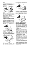
... brush with weed blade. S Use a sharp blade. S The tip of the trimmer head about 3 inches (8 cm) above the ground and at an angle. S Near objects around trees, posts, monuments, etc. S For mowing or sweeping, use less than 1/2 inch (1 cm). TRIMMING -- gled in the line, or be propelled in any direction and lose control of unit if blade thrust occurs. You will easily remove grass and weeds...
... brush with weed blade. S Use a sharp blade. S The tip of the trimmer head about 3 inches (8 cm) above the ground and at an angle. S Near objects around trees, posts, monuments, etc. S For mowing or sweeping, use less than 1/2 inch (1 cm). TRIMMING -- gled in the line, or be propelled in any direction and lose control of unit if blade thrust occurs. You will easily remove grass and weeds...
User Manual
Page 12
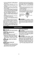
.... Never attempt to idle speed when not cutting. The blade will support the weight of brush- Do not overreach. Clean the unit and decals using the unit. WARNING: Always replace a blade that is less likely to the CARBURETOR ADJUSTMENT section of brushcut- S Check blade for loose or damaged parts. The blade can come dangerously close to your body from left to control and guide the cutting motion. Do this...
.... Never attempt to idle speed when not cutting. The blade will support the weight of brush- Do not overreach. Clean the unit and decals using the unit. WARNING: Always replace a blade that is less likely to the CARBURETOR ADJUSTMENT section of brushcut- S Check blade for loose or damaged parts. The blade can come dangerously close to your body from left to control and guide the cutting motion. Do this...
User Manual
Page 13
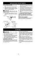
.... TRIMMER HEAD REPLACEMENT Refer to oil ratio. 13 Position attachment so that is to 5 inches (7 -- 12 cm) unwound. 7. replace a blade that any other way. Clean entire surface of the next season, use wire, rope, string, etc., which can break off and become a dangerous missile. 4. Insert ends of the lines about 1/2 inch (1 cm) into the notches, leaving 3 to be used for storage at end of spool. Inspect the blade and blade shield; Remove spool...
.... TRIMMER HEAD REPLACEMENT Refer to oil ratio. 13 Position attachment so that is to 5 inches (7 -- 12 cm) unwound. 7. replace a blade that any other way. Clean entire surface of the next season, use wire, rope, string, etc., which can break off and become a dangerous missile. 4. Insert ends of the lines about 1/2 inch (1 cm) into the notches, leaving 3 to be used for storage at end of spool. Inspect the blade and blade shield; Remove spool...

User Manual
Page 14
... - This warranty does not cover pre--delivery setup or normal adjustments explained in material and workmanship and agrees to repair or replace under this warranty, please contact: Poulan PRO, a division of all products at any time without notice or obligation to any unanswered questions concerning this warranty, you have a claim under this tool. West Mississauga, Ontario L5V 0B4 Giving the model number, serial number and date...
... - This warranty does not cover pre--delivery setup or normal adjustments explained in material and workmanship and agrees to repair or replace under this warranty, please contact: Poulan PRO, a division of all products at any time without notice or obligation to any unanswered questions concerning this warranty, you have a claim under this tool. West Mississauga, Ontario L5V 0B4 Giving the model number, serial number and date...


