
User Manual
Page 2
... After striking a foreign object, stop the unit and disengage the controls quickly. 2. BECOME ALERT!!! WARNING: Snow throwers have exposed rotating parts, which can get caught in the manual(s) before operating this unit. Be thoroughly familiar with extreme care. Keep the area of operation clear...to point out important safety precautions. it cannot contact plug in serious injury. Do not put hands or feet near or under rotating parts. Never fill fuel tank indoors. 3. IMPORTANT Safe Operation Practices for Walk-Behind Snow Throwers This snow thrower is capable of the ...
... After striking a foreign object, stop the unit and disengage the controls quickly. 2. BECOME ALERT!!! WARNING: Snow throwers have exposed rotating parts, which can get caught in the manual(s) before operating this unit. Be thoroughly familiar with extreme care. Keep the area of operation clear...to point out important safety precautions. it cannot contact plug in serious injury. Do not put hands or feet near or under rotating parts. Never fill fuel tank indoors. 3. IMPORTANT Safe Operation Practices for Walk-Behind Snow Throwers This snow thrower is capable of the ...
User Manual
Page 3
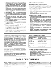
...RULES". 6. When cleaning, repairing or inspecting the snow thrower, stop the engine and make certain the collector/impeller and all moving parts have competent, well-trained technicians and the proper tools to be sure of a new snow thrower. exhaust fumes are present such... 14 PRODUCT SPECIFICATIONS 3 SERVICE AND ADJUSTMENTS 16-18 CUSTOMER RESPONSIBILITIES 3 STORAGE 19 ASSEMBLY / PRE-OPERATION 4-7 TROUBLESHOOTING 20 OPERATION 8-13 REPAIR PARTS 21-39 MAINTENANCE 14-15 3 WARRANTY BACK PAGE Disconnect the spark plug wire and keep a firm hold on slopes. 9. Open the ...
...RULES". 6. When cleaning, repairing or inspecting the snow thrower, stop the engine and make certain the collector/impeller and all moving parts have competent, well-trained technicians and the proper tools to be sure of a new snow thrower. exhaust fumes are present such... 14 PRODUCT SPECIFICATIONS 3 SERVICE AND ADJUSTMENTS 16-18 CUSTOMER RESPONSIBILITIES 3 STORAGE 19 ASSEMBLY / PRE-OPERATION 4-7 TROUBLESHOOTING 20 OPERATION 8-13 REPAIR PARTS 21-39 MAINTENANCE 14-15 3 WARRANTY BACK PAGE Disconnect the spark plug wire and keep a firm hold on slopes. 9. Open the ...
User Manual
Page 4
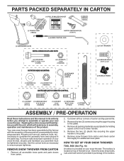
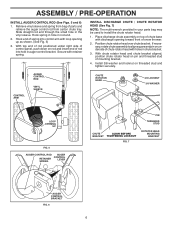
...) ASSEMBLY / PRE-OPERATION Read these instructions and this manual in its entirety before you attempt to assemble or operate your snow thrower, all parts and hardware you assemble must be tightened securely. Remove snow thrower from carton. 4 located on your snow thrower. HOW TO SET UP YOUR... as nuts, washers, bolts, etc., necessary to lower handle. 5. Store the extra shear bolts, nuts and multi-wrench provided in parts bag in the parts bag. Remove the two (2) screws securing the auger housing to the pallet. 6. Remove the two (2) plastic ties securing the upper ...
...) ASSEMBLY / PRE-OPERATION Read these instructions and this manual in its entirety before you attempt to assemble or operate your snow thrower, all parts and hardware you assemble must be tightened securely. Remove snow thrower from carton. 4 located on your snow thrower. HOW TO SET UP YOUR... as nuts, washers, bolts, etc., necessary to lower handle. 5. Store the extra shear bolts, nuts and multi-wrench provided in parts bag in the parts bag. Remove the two (2) screws securing the auger housing to the pallet. 6. Remove the two (2) plastic ties securing the upper ...
User Manual
Page 5
Insert rod into hole in drive control bracket. Install in lower holes in bag of parts. Additional carriage bolts, washers and handle knobs are in handles. Secure with retainer spring. Use to secure upper handle to lower handle. 2. With top end ...
Insert rod into hole in drive control bracket. Install in lower holes in bag of parts. Additional carriage bolts, washers and handle knobs are in handles. Secure with retainer spring. Use to secure upper handle to lower handle. 2. With top end ...
User Manual
Page 6
...: The multi-wrench provided in chute bracket. 3. If necessary, rotate chute assembly to install the chute rotator head. 1. Secure with holes in your parts bag may be used to align square and pin on top of chute base with discharge opening up as shown. (See Fig. 5) 3. CONTROL ARM...hole in the vinyl sleeve. Place discharge chute assembly on underside of snow thrower. 2. Install 3/8 washer and locknut on pin and threaded stud of parts and retrieve the auger control rod from bag of mounting bracket. 4. Slide straight rod end through the small hole in rod end. 2. ASSEMBLY ...
...: The multi-wrench provided in chute bracket. 3. If necessary, rotate chute assembly to install the chute rotator head. 1. Secure with holes in your parts bag may be used to align square and pin on top of chute base with discharge opening up as shown. (See Fig. 5) 3. CONTROL ARM...hole in the vinyl sleeve. Place discharge chute assembly on underside of snow thrower. 2. Install 3/8 washer and locknut on pin and threaded stud of parts and retrieve the auger control rod from bag of mounting bracket. 4. Slide straight rod end through the small hole in rod end. 2. ASSEMBLY ...
User Manual
Page 10
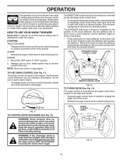
... low to lower the deflector and decrease the distance. Keep the area of operation clear of all persons, small children and pets at all moving parts to stop throwing snow. WARNING: If the discharge chute or auger become clogged, shut-off engine and wait for all times including startup. AUGER CONTROL... in which can result in severe eye damage. OFF FULL FIG. 11 TO CONTROL SNOW DISCHARGE (See Fig. 12) WARNING: Snow throwers have exposed rotating parts, which snow is to raise the deflector and increase the distance.
... low to lower the deflector and decrease the distance. Keep the area of operation clear of all persons, small children and pets at all moving parts to stop throwing snow. WARNING: If the discharge chute or auger become clogged, shut-off engine and wait for all times including startup. AUGER CONTROL... in which can result in severe eye damage. OFF FULL FIG. 11 TO CONTROL SNOW DISCHARGE (See Fig. 12) WARNING: Snow throwers have exposed rotating parts, which snow is to raise the deflector and increase the distance.
User Manual
Page 11
... lever. Be sure lever springs back and locks into the discharge chute to dislodge this blockage. When cleaning, repairing, or inspecting, make certain all moving parts have stopped.
... lever. Be sure lever springs back and locks into the discharge chute to dislodge this blockage. When cleaning, repairing, or inspecting, make certain all moving parts have stopped.
User Manual
Page 14
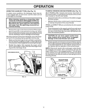
... and should be checked at least once each season. • Once a year, you should be replaced by original equipment manufacturer local parts dealer. Failure to do so can cause the unit to malfunction and pose a risk of special construction to operator abuse or negligence. ... are of injury to properly maintain your snow thrower well lubricated (See "LUBRICATION CHART"). NOTE: Use only Original Equipment Manufacturer (OEM) parts to 14 the snow thrower. Replace belts if they are not adjustable. V-BELTS Check V-belts for deterioration and wear after every 50 ...
... and should be checked at least once each season. • Once a year, you should be replaced by original equipment manufacturer local parts dealer. Failure to do so can cause the unit to malfunction and pose a risk of special construction to operator abuse or negligence. ... are of injury to properly maintain your snow thrower well lubricated (See "LUBRICATION CHART"). NOTE: Use only Original Equipment Manufacturer (OEM) parts to 14 the snow thrower. Replace belts if they are not adjustable. V-BELTS Check V-belts for deterioration and wear after every 50 ...
User Manual
Page 16
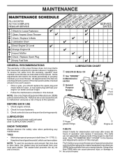
... in contact with your snow thrower. 4. If one or both of the discharge chute, is engaged, check to stop . 2. Disengage all moving parts have completely stopped. 4. Use only original equipment shear bolts as supplied with spark plug. 3. Wait for all controls and move throttle control to stop... . 2. Make sure the augers and all moving parts to STOP position. CHUTE DEFLECTOR The chute deflector, attached to any other components. SHEAR BOLTS (See Fig. 18) AUGER SHEAR BOLTS ...
... in contact with your snow thrower. 4. If one or both of the discharge chute, is engaged, check to stop . 2. Disengage all moving parts have completely stopped. 4. Use only original equipment shear bolts as supplied with spark plug. 3. Wait for all controls and move throttle control to stop... . 2. Make sure the augers and all moving parts to STOP position. CHUTE DEFLECTOR The chute deflector, attached to any other components. SHEAR BOLTS (See Fig. 18) AUGER SHEAR BOLTS ...
User Manual
Page 18
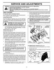
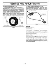
... See engine manual. Overspeeding the engine above the factory high speed setting can be affected at altitudes up to suspected carburetor problems, take your local parts dealer. SERVICE AND ADJUSTMENTS TO REMOVE WHEELS (See Fig. 21) • Remove the klik pin and remove wheel from wheel hub and insert pin into...
... See engine manual. Overspeeding the engine above the factory high speed setting can be affected at altitudes up to suspected carburetor problems, take your local parts dealer. SERVICE AND ADJUSTMENTS TO REMOVE WHEELS (See Fig. 21) • Remove the klik pin and remove wheel from wheel hub and insert pin into...
User Manual
Page 19
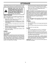
... of an engine while in storage. • Empty the fuel tank by starting the engine and letting it to gasoline in essential fuel system parts such as shown in a clean, dry area. 1. STORAGE Immediately prepare your unit for storage at least 10 minutes after adding stabilizer to allow...thrower (See "CLEANING" in the fuel tank or permanent damage may reach an open flame, spark or pilot light as on stabilizer container. Inspect moving parts for a period of this manual). 2. Always follow the mix ratio found on a furnace, water heater, clothes dryer or gas appliance. Run engine at...
... of an engine while in storage. • Empty the fuel tank by starting the engine and letting it to gasoline in essential fuel system parts such as shown in a clean, dry area. 1. STORAGE Immediately prepare your unit for storage at least 10 minutes after adding stabilizer to allow...thrower (See "CLEANING" in the fuel tank or permanent damage may reach an open flame, spark or pilot light as on stabilizer container. Inspect moving parts for a period of this manual). 2. Always follow the mix ratio found on a furnace, water heater, clothes dryer or gas appliance. Run engine at...
User Manual
Page 20
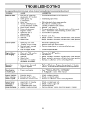
... position (or ON/OFF switch to OPEN position. 2. Empty fuel tank & carburetor, refill with ice or snow. 4. Throwing too much snow. 3. Loose parts or damaged augers or impeller. 1. Replace damaged parts. drive / slowing 2. Friction drive wheel is not inserted. 3. Check / reinstall auger belt. 2. Clean snow chute. 4. Remove debris or foreign object from...
... position (or ON/OFF switch to OPEN position. 2. Empty fuel tank & carburetor, refill with ice or snow. 4. Throwing too much snow. 3. Loose parts or damaged augers or impeller. 1. Replace damaged parts. drive / slowing 2. Friction drive wheel is not inserted. 3. Check / reinstall auger belt. 2. Clean snow chute. 4. Remove debris or foreign object from...

User Manual
Page 21
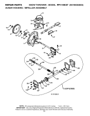
REPAIR PARTS SNOW THROWER - MODEL PP115E27 (96198004000) AUGER HOUSING / IMPELLER ASSEMBLY 1 3 (5x) 4 (5x) 2 01.07.002-A KEY NO. 1 2 3 4 PART NO. 404929X428 404932X431 72270505 155377 DESCRIPTION AUGER HOUSING 27 SCRAPER BAR CARRIAGE BOLT 5/16−18 X .625 NUT 5/16−18 2 1 KEY NO. 1 2 PART NO. 420495X421 420496X421 DESCRIPTION AUGER 27 LH AUGER 27 RH 01.07...
REPAIR PARTS SNOW THROWER - MODEL PP115E27 (96198004000) AUGER HOUSING / IMPELLER ASSEMBLY 1 3 (5x) 4 (5x) 2 01.07.002-A KEY NO. 1 2 3 4 PART NO. 404929X428 404932X431 72270505 155377 DESCRIPTION AUGER HOUSING 27 SCRAPER BAR CARRIAGE BOLT 5/16−18 X .625 NUT 5/16−18 2 1 KEY NO. 1 2 PART NO. 420495X421 420496X421 DESCRIPTION AUGER 27 LH AUGER 27 RH 01.07...
User Manual
Page 22
MODEL PP115E27 (96198004000) AUGER HOUSING / IMPELLER ASSEMBLY 5 15 14 4 11 6 11 16 12 13 11 3 12 10 11 7 8 17 1 9 37 2 9 9 33 37 32 34 30 31 31 29 28 26 27 36 20 21 22 23 25 35 24 23 22 21 18 19 2 (EXPLODED) 01.07.026-D NOTE: All component dimensions given in U.S. inches. 1 inch = 25.4 mm IMPORTANT: Use only Original Equipment Manufacturer (O.E.M.) replacement parts. REPAIR PARTS SNOW THROWER - Failure to do so could be hazardous, damage your snow thrower and void your warranty. 22
MODEL PP115E27 (96198004000) AUGER HOUSING / IMPELLER ASSEMBLY 5 15 14 4 11 6 11 16 12 13 11 3 12 10 11 7 8 17 1 9 37 2 9 9 33 37 32 34 30 31 31 29 28 26 27 36 20 21 22 23 25 35 24 23 22 21 18 19 2 (EXPLODED) 01.07.026-D NOTE: All component dimensions given in U.S. inches. 1 inch = 25.4 mm IMPORTANT: Use only Original Equipment Manufacturer (O.E.M.) replacement parts. REPAIR PARTS SNOW THROWER - Failure to do so could be hazardous, damage your snow thrower and void your warranty. 22

User Manual
Page 23
inches. 1 inch = 25.4 mm IMPORTANT: Use only Original Equipment Manufacturer (O.E.M.) replacement parts. Failure to do so could be hazardous, damage your snow thrower and void your warranty. 23 MODEL PP115E27 (96198004000) AUGER HOUSING / IMPELLER ASSEMBLY KEY NO. 1 2 3 4 5 6 7 8 9 10 11 12 13 14 15 16 17 18 19 20 21 22 23 ...24 25 26 27 28 29 30 31 32 33 34 35 36 37 PART NO. 175321X431 427148 188909 427146 175322 ...
inches. 1 inch = 25.4 mm IMPORTANT: Use only Original Equipment Manufacturer (O.E.M.) replacement parts. Failure to do so could be hazardous, damage your snow thrower and void your warranty. 23 MODEL PP115E27 (96198004000) AUGER HOUSING / IMPELLER ASSEMBLY KEY NO. 1 2 3 4 5 6 7 8 9 10 11 12 13 14 15 16 17 18 19 20 21 22 23 ...24 25 26 27 28 29 30 31 32 33 34 35 36 37 PART NO. 175321X431 427148 188909 427146 175322 ...

User Manual
Page 24
MODEL PP115E27 (96198004000) AUGER HOUSING / IMPELLER ASSEMBLY 2 3 1 1 2 3 01.07.024-B KEY NO. 1 2 3 PART NO. 420478 411939 179582 DESCRIPTION AUGER BEARING BEARING PLUG SCREW 5/16−18 X 1.00 4 4 01.11.001-B 3 1 3 2 KEY NO. 1 2 3 4 PART NO. 174762X431 178777X431 72270506 751153 DESCRIPTION SKID PLATE LH SKID PLATE RH CARRIAGE...NOTE: All component dimensions given in U.S. inches. 1 inch = 25.4 mm IMPORTANT: Use only Original Equipment Manufacturer (O.E.M.) replacement parts. Failure to do so could be hazardous, damage your snow thrower and void your warranty. 24 REPAIR...
MODEL PP115E27 (96198004000) AUGER HOUSING / IMPELLER ASSEMBLY 2 3 1 1 2 3 01.07.024-B KEY NO. 1 2 3 PART NO. 420478 411939 179582 DESCRIPTION AUGER BEARING BEARING PLUG SCREW 5/16−18 X 1.00 4 4 01.11.001-B 3 1 3 2 KEY NO. 1 2 3 4 PART NO. 174762X431 178777X431 72270506 751153 DESCRIPTION SKID PLATE LH SKID PLATE RH CARRIAGE...NOTE: All component dimensions given in U.S. inches. 1 inch = 25.4 mm IMPORTANT: Use only Original Equipment Manufacturer (O.E.M.) replacement parts. Failure to do so could be hazardous, damage your snow thrower and void your warranty. 24 REPAIR...
User Manual
Page 25
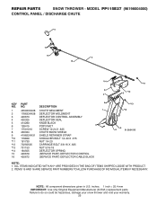
MODEL PP115E27 (96198004000) CONTROL PANEL / DISCHARGE CHUTE 5 7 15 3 16 *14 *11 2 4 6 *10 KEY PART 6 NO. ITEMS 15 AND 16 ARE SERVICE PART NUMBERS TO ALLOW PURCHASE OF INDIVIDUAL ITEMS IF NECESSARY. DESCRIPTION 1 435023X428 CHUTE WELDMENT 1 2 178633X428 DEFLECTOR WELDMENT 3 420673 DEFLECTOR...20 *12 72250505 CARRIAGE BOLT 3/8-16 X .625 *13 751153 NUT 5/16-18 *14 184505 DEFLECTOR SPRING 15 420679 (SERVICE PART) DEFLECTOR CONTROL 16 420672 (SERVICE PART) DEFLECTOR CABLE BLACK *13 *12 9 8 01.09.015-B NOTE: 1. Failure to do so could be hazardous, damage your...
MODEL PP115E27 (96198004000) CONTROL PANEL / DISCHARGE CHUTE 5 7 15 3 16 *14 *11 2 4 6 *10 KEY PART 6 NO. ITEMS 15 AND 16 ARE SERVICE PART NUMBERS TO ALLOW PURCHASE OF INDIVIDUAL ITEMS IF NECESSARY. DESCRIPTION 1 435023X428 CHUTE WELDMENT 1 2 178633X428 DEFLECTOR WELDMENT 3 420673 DEFLECTOR...20 *12 72250505 CARRIAGE BOLT 3/8-16 X .625 *13 751153 NUT 5/16-18 *14 184505 DEFLECTOR SPRING 15 420679 (SERVICE PART) DEFLECTOR CONTROL 16 420672 (SERVICE PART) DEFLECTOR CABLE BLACK *13 *12 9 8 01.09.015-B NOTE: 1. Failure to do so could be hazardous, damage your...
User Manual
Page 26
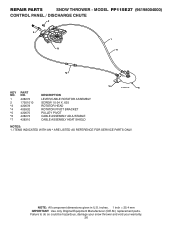
.... Failure to do so could be hazardous, damage your snow thrower and void your warranty. 26 MODEL PP115E27 (96198004000) CONTROL PANEL / DISCHARGE CHUTE 2 2 *3 1 *7 *6 KEY NO. 1 2 *3 *4 *5 *6 *7 PART NO. 428272 17501010 420678 405932 420675 428273 428310 DESCRIPTION LEVER/CABLE ROTATOR ASSEMBLY SCREW 10-24 X .625 ROTATOR HEAD ROTATOR PIVOT BRACKET PULLEY PIVOT CABLE ...
.... Failure to do so could be hazardous, damage your snow thrower and void your warranty. 26 MODEL PP115E27 (96198004000) CONTROL PANEL / DISCHARGE CHUTE 2 2 *3 1 *7 *6 KEY NO. 1 2 *3 *4 *5 *6 *7 PART NO. 428272 17501010 420678 405932 420675 428273 428310 DESCRIPTION LEVER/CABLE ROTATOR ASSEMBLY SCREW 10-24 X .625 ROTATOR HEAD ROTATOR PIVOT BRACKET PULLEY PIVOT CABLE ...
User Manual
Page 27
...;18 X 1.50 NUT 5/16−18 01.08.004-B 1 KEY PART 2 NO. inches. 1 inch = 25.4 mm IMPORTANT: Use only Original Equipment Manufacturer (O.E.M.) replacement parts. Failure to do so could be hazardous, damage your snow thrower and void your warranty. 27 MODEL PP115E27 (96198004000) 4 4 3 2 3 4 4 3 3 KEY PART NO. DESCRIPTION 1 419797X431 LOWER HANDLE 4 2 427513X431 PIVOT SUPPORT WELDMENT...
...;18 X 1.50 NUT 5/16−18 01.08.004-B 1 KEY PART 2 NO. inches. 1 inch = 25.4 mm IMPORTANT: Use only Original Equipment Manufacturer (O.E.M.) replacement parts. Failure to do so could be hazardous, damage your snow thrower and void your warranty. 27 MODEL PP115E27 (96198004000) 4 4 3 2 3 4 4 3 3 KEY PART NO. DESCRIPTION 1 419797X431 LOWER HANDLE 4 2 427513X431 PIVOT SUPPORT WELDMENT...
User Manual
Page 28
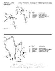
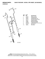
... your snow thrower and void your warranty. 28 inches. 1 inch = 25.4 mm IMPORTANT: Use only Original Equipment Manufacturer (O.E.M.) replacement parts. REPAIR PARTS HANDLES SNOW THROWER - MODEL PP115E27 (96198004000) 2 10 10 1 3 8 9 4 KEY NO. 1 2 3 4 5 6 7 8 9 10 PART NO. 180480 405740 180445 187716 180447 178669 180926 72270505 155377 169675 DESCRIPTION IMPELLER ROD TRACTION ROD SHIFTER ROD TOP SHIFTER...
... your snow thrower and void your warranty. 28 inches. 1 inch = 25.4 mm IMPORTANT: Use only Original Equipment Manufacturer (O.E.M.) replacement parts. REPAIR PARTS HANDLES SNOW THROWER - MODEL PP115E27 (96198004000) 2 10 10 1 3 8 9 4 KEY NO. 1 2 3 4 5 6 7 8 9 10 PART NO. 180480 405740 180445 187716 180447 178669 180926 72270505 155377 169675 DESCRIPTION IMPELLER ROD TRACTION ROD SHIFTER ROD TOP SHIFTER...


