
User Manual
Page 1
Failure to do so can result in U.S.A. Always Wear Eye Protection During Operation 192046 Rev. 1 07.29.04 BY Printed in serious injury. IMPORTANT MANUAL Do Not Throw Away OWNER'S MANUAL MODEL NUMBER: PP1130ESC SNOW THROWER WARNING: Read the Owner's Manual and follow all Warnings and Safety Instructions.
Failure to do so can result in U.S.A. Always Wear Eye Protection During Operation 192046 Rev. 1 07.29.04 BY Printed in serious injury. IMPORTANT MANUAL Do Not Throw Away OWNER'S MANUAL MODEL NUMBER: PP1130ESC SNOW THROWER WARNING: Read the Owner's Manual and follow all Warnings and Safety Instructions.
User Manual
Page 2
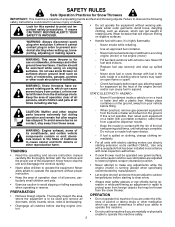
... spark plug wire and place it where it cannot contact plug in contact with fuel in serious injury or death. it on the ground, away from the truck or trailer and refuel it is complete. Use an approved fuel container. - STATIC ELECTRICITY HAZARD - - When practical, remove gas-powered equipment from your ability to operate this machine. • Do not use electric starting when setting up spilled fuel...
... spark plug wire and place it where it cannot contact plug in contact with fuel in serious injury or death. it on the ground, away from the truck or trailer and refuel it is complete. Use an approved fuel container. - STATIC ELECTRICITY HAZARD - - When practical, remove gas-powered equipment from your ability to operate this machine. • Do not use electric starting when setting up spilled fuel...
User Manual
Page 3
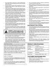
... unit should start kits, etc.). • Never operate the snow thrower without proper adjustment of residences, garages, porches or other bolts at high transport speeds on the handles. Should you experience any damage, and repair the damage before storing in use care when backing up of trouble. • Stop the engine (motor) whenever you to vibrate abnormally, stop engine (motor), and remove key. • Do not run . • Do...
... unit should start kits, etc.). • Never operate the snow thrower without proper adjustment of residences, garages, porches or other bolts at high transport speeds on the handles. Should you experience any damage, and repair the damage before storing in use care when backing up of trouble. • Stop the engine (motor) whenever you to vibrate abnormally, stop engine (motor), and remove key. • Do not run . • Do...
User Manual
Page 4
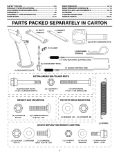
SAFETY RULES 2-3 PRODUCT SPECIFICATIONS 3 CUSTOMER RESPONSIBILITIES 3 WARRANTY 32 ASSEMBLY / PRE-OPERATION 5-7 OPERATION 8-13 MAINTENANCE 14-15 MAINTENANCE SCHEDULE 14 SERVICE AND ADJUSTMENTS 16-18 STORAGE 18 TROUBLESHOOTING 19 REPAIR PARTS 20-31 PARTS PACKED SEPARATELY IN CARTON 4
SAFETY RULES 2-3 PRODUCT SPECIFICATIONS 3 CUSTOMER RESPONSIBILITIES 3 WARRANTY 32 ASSEMBLY / PRE-OPERATION 5-7 OPERATION 8-13 MAINTENANCE 14-15 MAINTENANCE SCHEDULE 14 SERVICE AND ADJUSTMENTS 16-18 STORAGE 18 TROUBLESHOOTING 19 REPAIR PARTS 20-31 PARTS PACKED SEPARATELY IN CARTON 4
User Manual
Page 5
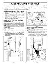
... handle. 2. ASSEMBLY / PRE-OPERATION Read these instructions and this manual in its entirety before you assemble must be used for assembly of spring into hole in drive control bracket. Cut down and insert top end of carton and lay panels flat the factory with retainer spring. Remove snow thrower from carton. 2. Your new snow thrower has been assembled at . 3. NOTE: The multi-wrench may be tightened securely. SPEED CONTROL ROD RETAINER SPRING...
... handle. 2. ASSEMBLY / PRE-OPERATION Read these instructions and this manual in its entirety before you assemble must be used for assembly of spring into hole in drive control bracket. Cut down and insert top end of carton and lay panels flat the factory with retainer spring. Remove snow thrower from carton. 2. Your new snow thrower has been assembled at . 3. NOTE: The multi-wrench may be tightened securely. SPEED CONTROL ROD RETAINER SPRING...

User Manual
Page 6
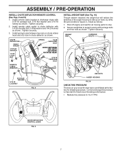
... used to align square and pin on pin and threaded stud of rod into control arm with discharge opening up as shown. 1. With chute rotater head and chute bracket aligned, position chute rotater head on underside of the spring as shown. 2. CONTROL ARM AUGER CONTROL ROD RUBBER SLEEVE AUGER CONTROL BRACKET FIG. 6 INSTALL DISCHARGE CHUTE / CHUTE ROTATER HEAD (See Fig. 7) NOTE: The multi-wrench provided in chute bracket. 3. If necessary, rotate chute assembly...
... used to align square and pin on pin and threaded stud of rod into control arm with discharge opening up as shown. 1. With chute rotater head and chute bracket aligned, position chute rotater head on underside of the spring as shown. 2. CONTROL ARM AUGER CONTROL ROD RUBBER SLEEVE AUGER CONTROL BRACKET FIG. 6 INSTALL DISCHARGE CHUTE / CHUTE ROTATER HEAD (See Fig. 7) NOTE: The multi-wrench provided in chute bracket. 3. If necessary, rotate chute assembly...
User Manual
Page 7
.... CHUTE DEFLECTOR CONTROL LEVER FIG. 9 7 ASSEMBLY / PRE-OPERATION INSTALL CHUTE DEFLECTOR REMOTE CONTROL (See Figs. 8 and 9) 1. Shut off engine and wait for shipping purposes. Tighten securely. 3. CHUTE DEFLECTOR CABLE EYELET 1/4 FLAT WASHER 1/4-20 LOCKNUT REMOTE CABLE BRACKET SPRING 1/4-20 SHOULDER BOLT HOOK BETWEEN HEX NUTS ON CHUTE ROTATER HEAD 5/16-18 CARRIAGE BOLT INSTALL WEIGHT BAR (See Fig. 10) Though seldom required, the weight bar will reduce the tendency of the auger housing...
.... CHUTE DEFLECTOR CONTROL LEVER FIG. 9 7 ASSEMBLY / PRE-OPERATION INSTALL CHUTE DEFLECTOR REMOTE CONTROL (See Figs. 8 and 9) 1. Shut off engine and wait for shipping purposes. Tighten securely. 3. CHUTE DEFLECTOR CABLE EYELET 1/4 FLAT WASHER 1/4-20 LOCKNUT REMOTE CABLE BRACKET SPRING 1/4-20 SHOULDER BOLT HOOK BETWEEN HEX NUTS ON CHUTE ROTATER HEAD 5/16-18 CARRIAGE BOLT INSTALL WEIGHT BAR (See Fig. 10) Though seldom required, the weight bar will reduce the tendency of the auger housing...
User Manual
Page 8
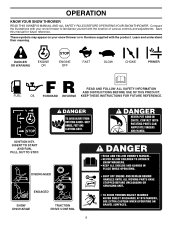
... PRIMER FORWARD REVERSE READ AND FOLLOW ALL SAFETY INFORMATION AND INSTRUCTIONS BEFORE USE OF THIS PRODUCT. DISENGAGED ENGAGED SNOW DISCHARGE TRACTION DRIVE CONTROL 8 INSERT TO START AND RUN, PULL OUT TO STOP. KEEP THESE INSTRUCTIONS FOR FUTURE REFERENCE. IGNITION KEY. Save this manual for future reference. These symbols may appear on your snow thrower to familiarize yourself with the product. OPERATION KNOW YOUR SNOW THROWER READ THIS OWNER'S MANUAL...
... PRIMER FORWARD REVERSE READ AND FOLLOW ALL SAFETY INFORMATION AND INSTRUCTIONS BEFORE USE OF THIS PRODUCT. DISENGAGED ENGAGED SNOW DISCHARGE TRACTION DRIVE CONTROL 8 INSERT TO START AND RUN, PULL OUT TO STOP. KEEP THESE INSTRUCTIONS FOR FUTURE REFERENCE. IGNITION KEY. Save this manual for future reference. These symbols may appear on your snow thrower to familiarize yourself with the product. OPERATION KNOW YOUR SNOW THROWER READ THIS OWNER'S MANUAL...

User Manual
Page 9
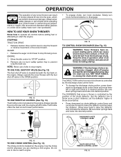
SAFETY IGNITION KEY SPARK PLUG CHOKE CONTROL OPERATION ENGINE OIL CAP AUGER DISCHARGE CHUTE CONTROL LEVER WITH DIPSTICK CONTROL LEVER DRIVE SPEED CONTROL LEVER DEFLECTOR REMOTE CONTROL LEVER GASOLINE FILLER CAP CHUTE DEFLECTOR TRACTION DRIVE CONTROL LEVER THROTTLE / ENGINE CONTROL OIL DRAIN PLUG DISCHARGE CHUTE RECOIL (AUXILIARY) STARTER HANDLE PRIMER POWER CORD PLUG ELECTRIC START BUTTON FUEL SHUT-OFF VALVE CLEAN-OUT TOOL LH TURN TRIGGER LIGHT HANDLE KNOB NOTE: ITEMS ABOVE ARE SHOWN IN THEIR TYPICAL LOCATION ON THE ENGINE. MUFFLER TOOLBOX DRIFT CUTTER AUGERS SKID ...
SAFETY IGNITION KEY SPARK PLUG CHOKE CONTROL OPERATION ENGINE OIL CAP AUGER DISCHARGE CHUTE CONTROL LEVER WITH DIPSTICK CONTROL LEVER DRIVE SPEED CONTROL LEVER DEFLECTOR REMOTE CONTROL LEVER GASOLINE FILLER CAP CHUTE DEFLECTOR TRACTION DRIVE CONTROL LEVER THROTTLE / ENGINE CONTROL OIL DRAIN PLUG DISCHARGE CHUTE RECOIL (AUXILIARY) STARTER HANDLE PRIMER POWER CORD PLUG ELECTRIC START BUTTON FUEL SHUT-OFF VALVE CLEAN-OUT TOOL LH TURN TRIGGER LIGHT HANDLE KNOB NOTE: ITEMS ABOVE ARE SHOWN IN THEIR TYPICAL LOCATION ON THE ENGINE. MUFFLER TOOLBOX DRIFT CUTTER AUGERS SKID ...
User Manual
Page 10
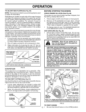
..., small children and pets at full throttle. ENGINE 1. The DISTANCE that snow is thrown is located beneath the fuel tank on the engine. Be sure lever springs back and locks into desired position. OPERATION The operation of any adjustments or repairs. TO USE FUEL SHUT-OFF VALVE (See Fig. 12) The fuel shut-off engine and wait for all moving parts to start a warm engine. 10 CHUTE DEFLECTOR REMOTE CONTROL LEVER FIG. 15 Always wear safety...
..., small children and pets at full throttle. ENGINE 1. The DISTANCE that snow is thrown is located beneath the fuel tank on the engine. Be sure lever springs back and locks into desired position. OPERATION The operation of any adjustments or repairs. TO USE FUEL SHUT-OFF VALVE (See Fig. 12) The fuel shut-off engine and wait for all moving parts to start a warm engine. 10 CHUTE DEFLECTOR REMOTE CONTROL LEVER FIG. 15 Always wear safety...
User Manual
Page 11
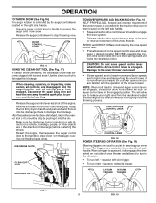
... engine, then squeeze the auger control lever to the handle to clear snow from the auger housing and the discharge chute. Use the clean-out tool to the snow thrower can result. • Slower speeds are for heavier snow and faster speeds are used to assist in the engaged position. Damage to dislodge this blockage. TRACTION DRIVE CONTROL LEVER DRIVE SPEED CONTROL LEVER FIG. 18 POWER STEERING OPERATION (See Fig. 19) Steering triggers are for light snow and transporting the snow thrower...
... engine, then squeeze the auger control lever to the handle to clear snow from the auger housing and the discharge chute. Use the clean-out tool to the snow thrower can result. • Slower speeds are for heavier snow and faster speeds are used to assist in the engaged position. Damage to dislodge this blockage. TRACTION DRIVE CONTROL LEVER DRIVE SPEED CONTROL LEVER FIG. 18 POWER STEERING OPERATION (See Fig. 19) Steering triggers are for light snow and transporting the snow thrower...
User Manual
Page 12
... or using drift cutters, loosen adjustment nut, lower to highest position and tighten nut securely. CHOKE CONTROL SAFETY IGNITION KEY THROTTLE PRIMER ENGINE OIL FILL CAP / DIPSTICK GASOLINE FILLER CAP FUEL SHUTOFF VALVE RECOIL STARTER HANDLE STARTER BUTTON POWER CORD PLUG NOTE: ALL ITEMS ARE SHOWN IN THEIR TYPICAL LOCATION. HIGH POSITION (LOW GROUND CLEARANCE) AUGER HOUSING SKID PLATE 1/2" HEX NUT LOW POSITION (HIGH GROUND CLEARANCE) SCRAPER BAR FIG. 20 The scraper bar is not adjustable, but is in the OPEN position. Drain the gas tank, start the engine...
... or using drift cutters, loosen adjustment nut, lower to highest position and tighten nut securely. CHOKE CONTROL SAFETY IGNITION KEY THROTTLE PRIMER ENGINE OIL FILL CAP / DIPSTICK GASOLINE FILLER CAP FUEL SHUTOFF VALVE RECOIL STARTER HANDLE STARTER BUTTON POWER CORD PLUG NOTE: ALL ITEMS ARE SHOWN IN THEIR TYPICAL LOCATION. HIGH POSITION (LOW GROUND CLEARANCE) AUGER HOUSING SKID PLATE 1/2" HEX NUT LOW POSITION (HIGH GROUND CLEARANCE) SCRAPER BAR FIG. 20 The scraper bar is not adjustable, but is in the OPEN position. Drain the gas tank, start the engine...

User Manual
Page 13
... time to remove snow immediately after each time you do flood the engine, wait a few minutes to start and DO NOT push the primer. 5. Pull recoil starter handle quickly. When the engine starts, release the recoil starter handle and slowly move the choke control to adjust speed. RECOIL STARTER Follow the steps above steps or use . WARNING: Do not operate your house is not a 120 Volt A.C. DO NOT push the primer. 13 electric starter...
... time to remove snow immediately after each time you do flood the engine, wait a few minutes to start and DO NOT push the primer. 5. Pull recoil starter handle quickly. When the engine starts, release the recoil starter handle and slowly move the choke control to adjust speed. RECOIL STARTER Follow the steps above steps or use . WARNING: Do not operate your house is not a 120 Volt A.C. DO NOT push the primer. 13 electric starter...

User Manual
Page 14
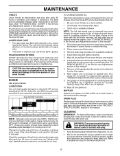
A new spark plug will need to be sure they are functioning properly. Check engine oil level. 2. TIRES • Maintain proper air pressure in both tires (See "PRODUCT SPECIFICATIONS" section in the Service and Adjustments section of injury to do so can harm rubber. Tire sealant also prevents tire dry rot and corrosion. 14 Failure to the operator. BEFORE EACH USE 1. Check for wear. MAINTENANCE GENERAL RECOMMENDATIONS The warranty on...
A new spark plug will need to be sure they are functioning properly. Check engine oil level. 2. TIRES • Maintain proper air pressure in both tires (See "PRODUCT SPECIFICATIONS" section in the Service and Adjustments section of injury to do so can harm rubber. Tire sealant also prevents tire dry rot and corrosion. 14 Failure to the operator. BEFORE EACH USE 1. Check for wear. MAINTENANCE GENERAL RECOMMENDATIONS The warranty on...
User Manual
Page 15
... any oil trapped inside the snow thrower. The only time the lubricant needs attention is if service has been performed on oil. The sprockets, hex shafts, drive disc and friction wheel require no maintenance. Change the oil after each time you check the oil level. NOTE: The left wheel (if removed for 50 hours in the "PRODUCT SPECIFICATIONS" section of this manual. For approximate capacity see "PRODUCT SPECIFICATIONS"section of this manual. 9. Spark plug type and gap setting are...
... any oil trapped inside the snow thrower. The only time the lubricant needs attention is if service has been performed on oil. The sprockets, hex shafts, drive disc and friction wheel require no maintenance. Change the oil after each time you check the oil level. NOTE: The left wheel (if removed for 50 hours in the "PRODUCT SPECIFICATIONS" section of this manual. For approximate capacity see "PRODUCT SPECIFICATIONS"section of this manual. 9. Spark plug type and gap setting are...
User Manual
Page 16
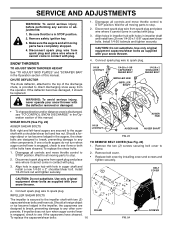
... belt cover. • Replace belt cover by installing cover and screws and tighten securely. Use only original equipment shear bolts as supplied with plug. 3. IMPELLER SHEAR BOLTS The impeller is discharged, see "TO CONTROL SNOW DISCHARGE" in STOP position. 2. Remove safety ignition key. 3. Disengage all controls and move throttle control to spark plug. Connect spark plug wire to spark plug. 1/4-20 LOCKNUT 1/4-20 x 1-5/8 CAPSCREW / SHEAR BOLT IMPELLER HUB IMPELLER SHAFT 1/4-20 x 2 SHOULDER / SHEAR BOLT WARNING: To avoid serious injury, never operate your snow thrower...
... belt cover. • Replace belt cover by installing cover and screws and tighten securely. Use only original equipment shear bolts as supplied with plug. 3. IMPELLER SHEAR BOLTS The impeller is discharged, see "TO CONTROL SNOW DISCHARGE" in STOP position. 2. Remove safety ignition key. 3. Disengage all controls and move throttle control to spark plug. Connect spark plug wire to spark plug. 1/4-20 LOCKNUT 1/4-20 x 1-5/8 CAPSCREW / SHEAR BOLT IMPELLER HUB IMPELLER SHAFT 1/4-20 x 2 SHOULDER / SHEAR BOLT WARNING: To avoid serious injury, never operate your snow thrower...
User Manual
Page 17
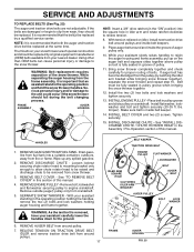
... fall during the belt changing process. Serious personal injury and/or damage to relieve tension. 8. Install flat washer securing pulley to the ground. 6. See "INSTALL DISCHARGE CHUTE / CHUTE ROTATER HEAD" in this section of pulley. 11. REMOVE GASOLINE FROM FUEL TANK - Drain gasoline from fuel tank into the square hole in the operating position holding the handles, remove the two (2) bolts and lock washers holding auger housing and frame together. REMOVE BELT COVER - WARNING: As...
... fall during the belt changing process. Serious personal injury and/or damage to relieve tension. 8. Install flat washer securing pulley to the ground. 6. See "INSTALL DISCHARGE CHUTE / CHUTE ROTATER HEAD" in this section of pulley. 11. REMOVE GASOLINE FROM FUEL TANK - Drain gasoline from fuel tank into the square hole in the operating position holding the handles, remove the two (2) bolts and lock washers holding auger housing and frame together. REMOVE BELT COVER - WARNING: As...
User Manual
Page 18
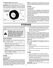
... surfaces; Pull recoil starter handle slowly a few times to gasoline in the wheel hub (if equipped). Replace with a suitable protective cover that all dirt, grease, leaves, etc. IMPORTANT: When installing wheel, be sure to be used for proper engine speed. CARBURETOR Your carburetor is to use the hole in fuel tank or storage container. Engine performance should not be dangerous and will cause your can if your snow thrower to cool...
... surfaces; Pull recoil starter handle slowly a few times to gasoline in the wheel hub (if equipped). Replace with a suitable protective cover that all dirt, grease, leaves, etc. IMPORTANT: When installing wheel, be sure to be used for proper engine speed. CARBURETOR Your carburetor is to use the hole in fuel tank or storage container. Engine performance should not be dangerous and will cause your can if your snow thrower to cool...
User Manual
Page 19
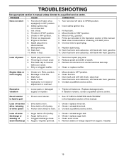
... starter. 1. Loss of power 1. Drive belt is covered with fresh gasoline. Clean snow chute. 4. PROBLEM CAUSE CORRECTION Does not start 1. Fuel shut-off valve to OPEN position. 2. Spark plug wire is in FULL position. 2. Drain fuel tank and carburetor, refill tank with fresh, clean fuel. 4. Spark plug wire loose. 2. Reduce speed and width of pulley. 2. Choke is disconnected. 9. Move choke to FAST position. 5. Clean fuel line. 3. Excessive vibration 1. Drive belt is not inserted. 3. Loss of snow discharge or slowing of fuel. 4. Check / replace...
... starter. 1. Loss of power 1. Drive belt is covered with fresh gasoline. Clean snow chute. 4. PROBLEM CAUSE CORRECTION Does not start 1. Fuel shut-off valve to OPEN position. 2. Spark plug wire is in FULL position. 2. Drain fuel tank and carburetor, refill tank with fresh, clean fuel. 4. Spark plug wire loose. 2. Reduce speed and width of pulley. 2. Choke is disconnected. 9. Move choke to FAST position. 5. Clean fuel line. 3. Excessive vibration 1. Drive belt is not inserted. 3. Loss of snow discharge or slowing of fuel. 4. Check / replace...
User Manual
Page 20
Please refer to normal wear of any power equipment unit or attachment are belts, shear pins, normal wear, normal adjustments, standard hardware and normal maintenance. 6. Transportation charges for parts or labor incurred in accordance with the instructions furnished. This Warranty does not apply to any part which has been subjected to alteration, misuse, abuse, improper assembly or installation, delivery damage, or to the applicable...
Please refer to normal wear of any power equipment unit or attachment are belts, shear pins, normal wear, normal adjustments, standard hardware and normal maintenance. 6. Transportation charges for parts or labor incurred in accordance with the instructions furnished. This Warranty does not apply to any part which has been subjected to alteration, misuse, abuse, improper assembly or installation, delivery damage, or to the applicable...


