
User Manual
Page 2
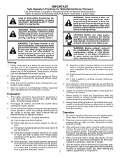
...of operation clear of amputating hands and feet and throwing objects. Exercise caution to observe the following safety instructions could result in moving parts. Wear footwear that will improve footing on clothing, change clothing immediately. 5. Do not use snow thrower on or cross- (b) Never...or hot engine. Caution should start to operate the equipment without wearing adequate winter garments. WARNING: Snow throwers have exposed rotating parts, which can get caught in serious injury. Be thoroughly familiar with the rim of the discharge opening at all clutches and...
...of operation clear of amputating hands and feet and throwing objects. Exercise caution to observe the following safety instructions could result in moving parts. Wear footwear that will improve footing on clothing, change clothing immediately. 5. Do not use snow thrower on or cross- (b) Never...or hot engine. Caution should start to operate the equipment without wearing adequate winter garments. WARNING: Snow throwers have exposed rotating parts, which can get caught in serious injury. Be thoroughly familiar with the rim of the discharge opening at all clutches and...
User Manual
Page 3
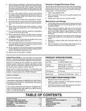
6. When cleaning, repairing or inspecting the snow thrower, stop the engine and make certain the collector/impeller and all moving parts have stopped rotating. 3. Do not run . 16. Never operate the snow thrower without good visibility or light. Never ...14-15 PRODUCT SPECIFICATIONS 3 SERVICE AND ADJUSTMENTS 16-18 CUSTOMER RESPONSIBILITIES 3 STORAGE 18 ASSEMBLY / PRE-OPERATION 4-7 TROUBLESHOOTING 19 OPERATION 8-13 REPAIR PARTS 20-38 MAINTENANCE SCHEDULE 14 3 WARRANTY BACK COVER Exercise extreme caution when operating on your footing, and keep the wire away from the ...
6. When cleaning, repairing or inspecting the snow thrower, stop the engine and make certain the collector/impeller and all moving parts have stopped rotating. 3. Do not run . 16. Never operate the snow thrower without good visibility or light. Never ...14-15 PRODUCT SPECIFICATIONS 3 SERVICE AND ADJUSTMENTS 16-18 CUSTOMER RESPONSIBILITIES 3 STORAGE 18 ASSEMBLY / PRE-OPERATION 4-7 TROUBLESHOOTING 19 OPERATION 8-13 REPAIR PARTS 20-38 MAINTENANCE SCHEDULE 14 3 WARRANTY BACK COVER Exercise extreme caution when operating on your footing, and keep the wire away from the ...
User Manual
Page 4
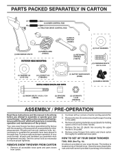
...been assembled at the factory with the unit, which will familiarize you assemble must be tightened securely. Cut down all parts and hardware you with the exception of carton and lay panels flat. 3. Remove all packing materials except plastic tie ...necessary to ensure proper tightness. 2. Remove snow thrower from carton. 4 located on your snow thrower, all four corners of those parts left unassembled for additional loose parts. PARTS PACKED SEPARATELY IN CARTON (1) AUGER CONTROL ROD (1) TRACTION DRIVE CONTROL ROD (1) DISCHARGE CHUTE (1) POWER CORD (198563) ROTATOR HEAD ...
...been assembled at the factory with the unit, which will familiarize you assemble must be tightened securely. Cut down all parts and hardware you with the exception of carton and lay panels flat. 3. Remove all packing materials except plastic tie ...necessary to ensure proper tightness. 2. Remove snow thrower from carton. 4 located on your snow thrower, all four corners of those parts left unassembled for additional loose parts. PARTS PACKED SEPARATELY IN CARTON (1) AUGER CONTROL ROD (1) TRACTION DRIVE CONTROL ROD (1) DISCHARGE CHUTE (1) POWER CORD (198563) ROTATOR HEAD ...
User Manual
Page 5
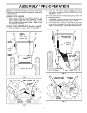
.... 2. Secure with retainer spring.install traction DRIVE control rod (See Figs. 3 and 4) The traction drive control rod has the long loop on the end of parts. Raise upper handle to lower handle. Insert rod into hole in bag of the spring as shown. 2. Install in lower holes in handles. Remove plastic...
.... 2. Secure with retainer spring.install traction DRIVE control rod (See Figs. 3 and 4) The traction drive control rod has the long loop on the end of parts. Raise upper handle to lower handle. Insert rod into hole in bag of the spring as shown. 2. Install in lower holes in handles. Remove plastic...

User Manual
Page 6
... CONTROL BRACKET FIG. 6 6 CONTROL ARM AUGER CONTROL ROD RUBBER SLEEVE INSTALL DISCHARGE CHUTE / CHUTE ROTATER HEAD (See Fig. 7) NOTE: The multi-wrench provided in your parts bag may be used to align square and pin on underside of snow thrower. 2.
... CONTROL BRACKET FIG. 6 6 CONTROL ARM AUGER CONTROL ROD RUBBER SLEEVE INSTALL DISCHARGE CHUTE / CHUTE ROTATER HEAD (See Fig. 7) NOTE: The multi-wrench provided in your parts bag may be used to align square and pin on underside of snow thrower. 2.

User Manual
Page 10
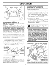
...severe injury from contact, or from material thrown from the discharge chute. HOW TO USE YOUR SNOW THROWER Know how to operate all moving parts to be thrown is controlled by the position of the chute deflector. STOPPING TRACTION DRIVE • Release traction drive control lever to start..., press downward on the engine. OFF FULL FIG. 13 TO CONTROL SNOW DISCHARGE (See Fig. 14) WARNING: Snow throwers have exposed rotating parts, which can result in desired position. Keep the area of operation clear of all times including startup. OPERATION The operation of any adjustments or...
...severe injury from contact, or from material thrown from the discharge chute. HOW TO USE YOUR SNOW THROWER Know how to operate all moving parts to be thrown is controlled by the position of the chute deflector. STOPPING TRACTION DRIVE • Release traction drive control lever to start..., press downward on the engine. OFF FULL FIG. 13 TO CONTROL SNOW DISCHARGE (See Fig. 14) WARNING: Snow throwers have exposed rotating parts, which can result in desired position. Keep the area of operation clear of all times including startup. OPERATION The operation of any adjustments or...

User Manual
Page 11
... the discharge chute to dislodge the blockage. NOTE: When both traction drive and auger control levers are disengaged and the auger/impeller and all moving parts have stopped. When cleaning, repairing, or inspecting, make certain all controls are engaged, the traction drive control lever will allow you are for light snow...
... the discharge chute to dislodge the blockage. NOTE: When both traction drive and auger control levers are disengaged and the auger/impeller and all moving parts have stopped. When cleaning, repairing, or inspecting, make certain all controls are engaged, the traction drive control lever will allow you are for light snow...
User Manual
Page 12
...Adjust skid plates evenly to bottom of the housing, it can easily be picked up and thrown by loosening the hex nuts, then moving parts to desired position. Shut off any spilled oil or fuel. Be sure both plates are located on dipstick is reversible. BEFORE STARTING THE ... add oil until the fuel lines and carburetor are adjusted to assure fuel freshness. Use fresh, clean, regular unleaded gasoline with snow thrower on your parts bag may be cleared is not recommended to give a 1/8" clearance between the scraper bar and the ground surface. See Storage Instructions for a few...
...Adjust skid plates evenly to bottom of the housing, it can easily be picked up and thrown by loosening the hex nuts, then moving parts to desired position. Shut off any spilled oil or fuel. Be sure both plates are located on dipstick is reversible. BEFORE STARTING THE ... add oil until the fuel lines and carburetor are adjusted to assure fuel freshness. Use fresh, clean, regular unleaded gasoline with snow thrower on your parts bag may be cleared is not recommended to give a 1/8" clearance between the scraper bar and the ground surface. See Storage Instructions for a few...

User Manual
Page 13
...thrower. 5. Pull recoil starter handle quickly. Insert safety ignition key (packed separately in a safe place. 2. Keep the extra safety ignition key in parts bag) into ignition slot until it clicks. BEFORE STOPPING Run the engine for a few minutes to warm up for a few minutes. Use the...to the "OFF" position. • Slightly overlap each attempt. OPERATION TO START ENGINE • Be sure fuel shut-off valve is in parts bag) into ignition slot until it clicks. receptacle. 6. Engine will not develop full power until it snap back against the starter. If ...
...thrower. 5. Pull recoil starter handle quickly. Insert safety ignition key (packed separately in a safe place. 2. Keep the extra safety ignition key in parts bag) into ignition slot until it clicks. BEFORE STOPPING Run the engine for a few minutes to warm up for a few minutes. Use the...to the "OFF" position. • Slightly overlap each attempt. OPERATION TO START ENGINE • Be sure fuel shut-off valve is in parts bag) into ignition slot until it clicks. receptacle. 6. Engine will not develop full power until it snap back against the starter. If ...
User Manual
Page 14
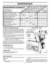
... will need to be sure they are functioning properly. NOTE: Use only Original Equipment Manufacturer (OEM) parts to service this snow thrower does not cover items that have been subjected to properly maintain your local parts dealer. LUBRICATION Keep your engine run better and last longer. • Follow the maintenance schedule in...
... will need to be sure they are functioning properly. NOTE: Use only Original Equipment Manufacturer (OEM) parts to service this snow thrower does not cover items that have been subjected to properly maintain your local parts dealer. LUBRICATION Keep your engine run better and last longer. • Follow the maintenance schedule in...
User Manual
Page 16
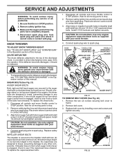
...discharged, see "TO CONTROL SNOW DISCHARGE" in impeller shaft and install two (2) new 1/4-20 x 1-5/8" capscrew/shear bolts. Wait for all moving parts to any service or adjustments: 1. Remove safety ignition key and disconnect spark plug wire from spark plug. SNOW THROWER TO ADJUST SNOW THROWER HEIGHT ...do not turn when auger control lever is engaged, check to any other components. To replace the shear bolts: 1. Wait for all moving parts have sheared. Remove safety ignition key and disconnect spark plug wire from spark plug. Place wire where it cannot come in contact with plug...
...discharged, see "TO CONTROL SNOW DISCHARGE" in impeller shaft and install two (2) new 1/4-20 x 1-5/8" capscrew/shear bolts. Wait for all moving parts to any service or adjustments: 1. Remove safety ignition key and disconnect spark plug wire from spark plug. SNOW THROWER TO ADJUST SNOW THROWER HEIGHT ...do not turn when auger control lever is engaged, check to any other components. To replace the shear bolts: 1. Wait for all moving parts have sheared. Remove safety ignition key and disconnect spark plug wire from spark plug. Place wire where it cannot come in contact with plug...
User Manual
Page 18
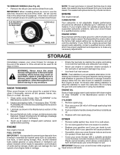
... and corrosion. CARBURETOR Your carburetor is still warm. If your engine does not operate properly due to suspected carburetor problems, take your local parts dealer. Allow the engine to protect it thoroughly, remove all nuts, bolts, screws, and pins are empty. • Never use plastic...engine-governed high speed needs adjusting, contact a qualified service center, which allows condensation to form and will void the warranty. Inspect moving parts for proper engine speed. Pour one season to rust. Do not empty the gas tank and carburetor if using ethanol or methanol) ...
... and corrosion. CARBURETOR Your carburetor is still warm. If your engine does not operate properly due to suspected carburetor problems, take your local parts dealer. Allow the engine to protect it thoroughly, remove all nuts, bolts, screws, and pins are empty. • Never use plastic...engine-governed high speed needs adjusting, contact a qualified service center, which allows condensation to form and will void the warranty. Inspect moving parts for proper engine speed. Pour one season to rust. Do not empty the gas tank and carburetor if using ethanol or methanol) ...

User Manual
Page 19
...Throwing too much snow. 3. Engine idles or runs roughly 1. Empty fuel tank & carburetor, refill with fresh, clean gasoline. Loose parts or damaged augers or impeller. 1. If vibration remains, contact an authorized service centre/department. Check / reinstall drive belt. Clogged ... object from augers / impeller. 19 Reconnect spark plug wire. 2. Carburetor is covered with fresh, clean gasoline. 4. Replace damaged parts. Safety ignition key is flooded. 8. Engine is not inserted. 3. Insert safety ignition key. 3. Prime as instructed in the ...
...Throwing too much snow. 3. Engine idles or runs roughly 1. Empty fuel tank & carburetor, refill with fresh, clean gasoline. Loose parts or damaged augers or impeller. 1. If vibration remains, contact an authorized service centre/department. Check / reinstall drive belt. Clogged ... object from augers / impeller. 19 Reconnect spark plug wire. 2. Carburetor is covered with fresh, clean gasoline. 4. Replace damaged parts. Safety ignition key is flooded. 8. Engine is not inserted. 3. Insert safety ignition key. 3. Prime as instructed in the ...

User Manual
Page 20
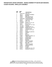
REPAIR PARTS SNOW THROWER - - inches. 1 inch = 25.4 mm IMPORTANT: Use only Original Equipment Manufacturer (O.E.M.) replacement parts. Failure to do so could be hazardous, damage your snow thrower and void your warranty. 20 MODEL NUMBER PP10527ES (96192002001) AUGER HOUSING / IMPELLER ASSEMBLY 5 11 6 15 14 13 4 12 16 11 12 3 11 1 9 10 2 11 7 8 17 33 32 34 30 31 31 29 26 28 27 35 18 25 24 23 22 21 19 01.07.004-B 36 20 21 22 23 2 (EXPLODED) NOTE: All component dimensions given in U.S.
REPAIR PARTS SNOW THROWER - - inches. 1 inch = 25.4 mm IMPORTANT: Use only Original Equipment Manufacturer (O.E.M.) replacement parts. Failure to do so could be hazardous, damage your snow thrower and void your warranty. 20 MODEL NUMBER PP10527ES (96192002001) AUGER HOUSING / IMPELLER ASSEMBLY 5 11 6 15 14 13 4 12 16 11 12 3 11 1 9 10 2 11 7 8 17 33 32 34 30 31 31 29 26 28 27 35 18 25 24 23 22 21 19 01.07.004-B 36 20 21 22 23 2 (EXPLODED) NOTE: All component dimensions given in U.S.
User Manual
Page 21
inches. 1 inch = 25.4 mm IMPORTANT: Use only Original Equipment Manufacturer (O.E.M.) replacement parts. REPAIR PARTS SNOW THROWER - - DESCRIPTION 175321X479 196710 188909 191079 175322 178675X008 192199 405400 73800400 74780426 155377 163183 19111507 10040500 74940516 180355 194189 407760 407761 407766 ... LH NOTE: All component dimensions given in U.S. Failure to do so could be hazardous, damage your snow thrower and void your warranty. 21 MODEL NUMBER PP10527ES (96192002001) AUGER HOUSING / IMPELLER ASSEMBLY KEY NO. 1 2 3 4 5 6 7 8 9 10 11 12 13 14 15 16 17 18 19 20 21 22 23 24 25 ...
inches. 1 inch = 25.4 mm IMPORTANT: Use only Original Equipment Manufacturer (O.E.M.) replacement parts. REPAIR PARTS SNOW THROWER - - DESCRIPTION 175321X479 196710 188909 191079 175322 178675X008 192199 405400 73800400 74780426 155377 163183 19111507 10040500 74940516 180355 194189 407760 407761 407766 ... LH NOTE: All component dimensions given in U.S. Failure to do so could be hazardous, damage your snow thrower and void your warranty. 21 MODEL NUMBER PP10527ES (96192002001) AUGER HOUSING / IMPELLER ASSEMBLY KEY NO. 1 2 3 4 5 6 7 8 9 10 11 12 13 14 15 16 17 18 19 20 21 22 23 24 25 ...
User Manual
Page 22
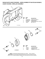
...: Use only Original Equipment Manufacturer (O.E.M.) replacement parts. NO. MODEL NUMBER PP10527ES (96192002001) AUGER HOUSING / IMPELLER ASSEMBLY 1 3 (5x) 4 (5x) 2 01.07.002-A KEY NO. 1 2 3 4 PART NO. 404929X428 404932X479 72270505 155377 DESCRIPTION AUGER HOUSING 27 SCRAPER BAR CARRIAGE BOLT 5/16−18 X .625 NUT 5/16−18 2 3 1 1 2 KEY PART NO. Failure to do so could be...
...: Use only Original Equipment Manufacturer (O.E.M.) replacement parts. NO. MODEL NUMBER PP10527ES (96192002001) AUGER HOUSING / IMPELLER ASSEMBLY 1 3 (5x) 4 (5x) 2 01.07.002-A KEY NO. 1 2 3 4 PART NO. 404929X428 404932X479 72270505 155377 DESCRIPTION AUGER HOUSING 27 SCRAPER BAR CARRIAGE BOLT 5/16−18 X .625 NUT 5/16−18 2 3 1 1 2 KEY PART NO. Failure to do so could be...
User Manual
Page 23
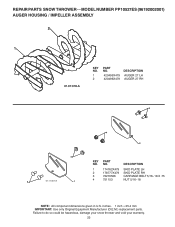
... snow thrower and void your warranty. 23 MODEL NUMBER PP10527ES (96192002001) AUGER HOUSING / IMPELLER ASSEMBLY 2 1 01.07.018-A KEY NO. 1 2 PART NO. 420495X479 420496X479 DESCRIPTION AUGER 27 LH AUGER 27 RH 3 4 2 4 KEY PART NO. inches. 1 inch = 25.4 mm IMPORTANT:... Use only Original Equipment Manufacturer (O.E.M.) replacement parts. DESCRIPTION 1 174762X479 SKID PLATE LH 2 178777X479 SKID PLATE RH ...
... snow thrower and void your warranty. 23 MODEL NUMBER PP10527ES (96192002001) AUGER HOUSING / IMPELLER ASSEMBLY 2 1 01.07.018-A KEY NO. 1 2 PART NO. 420495X479 420496X479 DESCRIPTION AUGER 27 LH AUGER 27 RH 3 4 2 4 KEY PART NO. inches. 1 inch = 25.4 mm IMPORTANT:... Use only Original Equipment Manufacturer (O.E.M.) replacement parts. DESCRIPTION 1 174762X479 SKID PLATE LH 2 178777X479 SKID PLATE RH ...
User Manual
Page 24
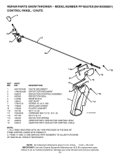
....4 mm IMPORTANT: Use only Original Equipment Manufacturer (O.E.M.) replacement parts. ITEMS 14 AND 15 ARE SERVICE PART NUMBERS TO ALLOW PURCHASE OF INDIVIDUAL ITEMS IF NECESSARY. *10 *9 *8 6 *12 *11 01.09.002-B NOTE: All component dimensions given in U.S. MODEL NUMBER PP10527ES (96192002001) CONTROL PANEL / CHUTE 5 7 14 3... 15 *13 KEY NO. 1 2 3 4 5 6 7 *8 *9 *10 *11 *12 *13 14 15 PART NO. 404770X428 178633X428 420673 420325 414280 128415 17501010 179829 179246 ...
....4 mm IMPORTANT: Use only Original Equipment Manufacturer (O.E.M.) replacement parts. ITEMS 14 AND 15 ARE SERVICE PART NUMBERS TO ALLOW PURCHASE OF INDIVIDUAL ITEMS IF NECESSARY. *10 *9 *8 6 *12 *11 01.09.002-B NOTE: All component dimensions given in U.S. MODEL NUMBER PP10527ES (96192002001) CONTROL PANEL / CHUTE 5 7 14 3... 15 *13 KEY NO. 1 2 3 4 5 6 7 *8 *9 *10 *11 *12 *13 14 15 PART NO. 404770X428 178633X428 420673 420325 414280 128415 17501010 179829 179246 ...

User Manual
Page 25
... 1 188303 STEER CABLE 2 74041024 SCREW 10−24 X 1.50 01.15.005-A NOTE: All component dimensions given in U.S. MODEL NUMBER PP10527ES (96192002001) CONTROL PANEL / CHUTE 2 2 *3 1 *6 KEY NO. 1 2 *3 *4 *5 *6 PART NO. 420337 17501010 420678 420677 420675 420674 *6 DESCRIPTION LEVER/CABLE ROTATOR ASSEMBLY SCREW 10−24 X .625 ROTATOR HEAD ROTATOR PIVOT BRACKET... be hazardous, damage your snow thrower and void your warranty. 25 inches. 1 inch = 25.4 mm IMPORTANT: Use only Original Equipment Manufacturer (O.E.M.) replacement parts. REPAIR PARTS SNOW THROWER - -
... 1 188303 STEER CABLE 2 74041024 SCREW 10−24 X 1.50 01.15.005-A NOTE: All component dimensions given in U.S. MODEL NUMBER PP10527ES (96192002001) CONTROL PANEL / CHUTE 2 2 *3 1 *6 KEY NO. 1 2 *3 *4 *5 *6 PART NO. 420337 17501010 420678 420677 420675 420674 *6 DESCRIPTION LEVER/CABLE ROTATOR ASSEMBLY SCREW 10−24 X .625 ROTATOR HEAD ROTATOR PIVOT BRACKET... be hazardous, damage your snow thrower and void your warranty. 25 inches. 1 inch = 25.4 mm IMPORTANT: Use only Original Equipment Manufacturer (O.E.M.) replacement parts. REPAIR PARTS SNOW THROWER - -
User Manual
Page 26
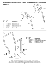
... to do so could be hazardous, damage your snow thrower and void your warranty. 26 MODEL NUMBER PP10527ES (96192002001) HANDLES 3 3 KEY NO. 1 2 3 4 5 PART NO. 419798X479 419799X479 74780524 74780528 751153 4 DESCRIPTION LOOP HANDLE LH LOOP HANDLE RH SCREW 5/16−18 X 1.50 SCREW 5/16−18 X 1.75 NUT 5/16&#...
... to do so could be hazardous, damage your snow thrower and void your warranty. 26 MODEL NUMBER PP10527ES (96192002001) HANDLES 3 3 KEY NO. 1 2 3 4 5 PART NO. 419798X479 419799X479 74780524 74780528 751153 4 DESCRIPTION LOOP HANDLE LH LOOP HANDLE RH SCREW 5/16−18 X 1.50 SCREW 5/16−18 X 1.75 NUT 5/16&#...


