
User Manual
Page 8
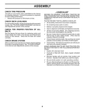
... location and function. CHECK DECK LEVELNESS For best cutting results, mower housing should be properly inflated for replacing motion and mower blade drive belts in safe operating condition. ✓ Be sure Operator Presence System and Reverse Operation System (ROS) are properly clamped. Verify that ...are routed correctly. CHECK FOR PROPER POSITION OF ALL BELTS See the figures that the belts are shown for leveling). ✓ Check mower and drive belts. CHECK BRAKE SYSTEM After you start the engine. ✓ Be sure brake system is operating...
... location and function. CHECK DECK LEVELNESS For best cutting results, mower housing should be properly inflated for replacing motion and mower blade drive belts in safe operating condition. ✓ Be sure Operator Presence System and Reverse Operation System (ROS) are properly clamped. Verify that ...are routed correctly. CHECK FOR PROPER POSITION OF ALL BELTS See the figures that the belts are shown for leveling). ✓ Check mower and drive belts. CHECK BRAKE SYSTEM After you start the engine. ✓ Be sure brake system is operating...
User Manual
Page 22
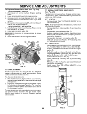
...held in "transmission disengaged" position. NOTE: Observe entire motion drive belt and position of all belt guides and keepers. • Remove belt from stationary idler (A) and clutching idler (B). • Remove belt from tractor. Carefully remove belt upwards from clutch pulley (M), both mandrel pulleys (R) and around... this section of tractor. The rear wheels must be serviced. SERVICE AND ADJUSTMENTS To Replace Mower Drive Belt (See Fig. 24) MOWER DRIVE BELT REMOVAL 1. MOWER DRIVE BELT INSTALLATION 1. Park tractor on a level, dry concrete or paved surface, then brake must lock...
...held in "transmission disengaged" position. NOTE: Observe entire motion drive belt and position of all belt guides and keepers. • Remove belt from stationary idler (A) and clutching idler (B). • Remove belt from tractor. Carefully remove belt upwards from clutch pulley (M), both mandrel pulleys (R) and around... this section of tractor. The rear wheels must be serviced. SERVICE AND ADJUSTMENTS To Replace Mower Drive Belt (See Fig. 24) MOWER DRIVE BELT REMOVAL 1. MOWER DRIVE BELT INSTALLATION 1. Park tractor on a level, dry concrete or paved surface, then brake must lock...
User Manual
Page 27
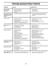
...vent holes from buildup of grass, leaves, and trash around mandrels. 1. Level mower deck. 3. Frozen idler pulley. 4. Mower drive belt worn. 9. Improper blades used. 11. Clean underside of mower housing. 4. Light switch is shifted into reverse 1. Turn light switch... underside of mower housing. 8. Replace blade mandrel. 5. Obstruction in "FAST" position. 2. Worn/damaged mower drive belt. 3. Frozen blade mandrel. 1. Remove obstruction. 2. Replace mower drive belt. 3. Replace blade mandrel. Engine speed too slow. 2. Wet grass. 4. Worn, bent or loose blade....
...vent holes from buildup of grass, leaves, and trash around mandrels. 1. Level mower deck. 3. Frozen idler pulley. 4. Mower drive belt worn. 9. Improper blades used. 11. Clean underside of mower housing. 4. Light switch is shifted into reverse 1. Turn light switch... underside of mower housing. 8. Replace blade mandrel. 5. Obstruction in "FAST" position. 2. Worn/damaged mower drive belt. 3. Frozen blade mandrel. 1. Remove obstruction. 2. Replace mower drive belt. 3. Replace blade mandrel. Engine speed too slow. 2. Wet grass. 4. Worn, bent or loose blade....
Parts Manual
Page 9
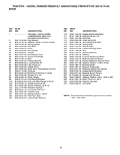
...27 Pulley Idler Flat 873 90 06-00 Lock Nut 3/8-16 532 19 43-26 Idler V-Groove 532 13 09-69 V-Belt, Drive 532 19 62-00 Shaft Asm. Pedal Brake Control 532 41 13-29 Console 874 49 05-40 Bolt Hex 5/16...189 190 205 211 216 221 225 226 227 230 232 233 279 PART NO. DESCRIPTION 532 19 43-22 Keeper Belt Centerspan 872 11 06-16 Bolt 3/8-16 unc x 2 532 19 72-89 Nut Push 532 40 62-08 ... 52-96 Washer Serrated 532 40 62-07 Link Shift NOTE: All component dimensions given in U.S. MODEL NUMBER PB20H42LT (96042014800), PRODUCT NO. 960 42 01-48 DRIVE KEY NO. 1 2 15 17 22 23 29 33 35 42 49 50 51 52 56 64 70 ...
...27 Pulley Idler Flat 873 90 06-00 Lock Nut 3/8-16 532 19 43-26 Idler V-Groove 532 13 09-69 V-Belt, Drive 532 19 62-00 Shaft Asm. Pedal Brake Control 532 41 13-29 Console 874 49 05-40 Bolt Hex 5/16...189 190 205 211 216 221 225 226 227 230 232 233 279 PART NO. DESCRIPTION 532 19 43-22 Keeper Belt Centerspan 872 11 06-16 Bolt 3/8-16 unc x 2 532 19 72-89 Nut Push 532 40 62-08 ... 52-96 Washer Serrated 532 40 62-07 Link Shift NOTE: All component dimensions given in U.S. MODEL NUMBER PB20H42LT (96042014800), PRODUCT NO. 960 42 01-48 DRIVE KEY NO. 1 2 15 17 22 23 29 33 35 42 49 50 51 52 56 64 70 ...


