
User Manual
Page 2
... exercised while using on a truck thrower for any adjustments while the engine (motor) is highly flammable (f) Keep the nozzle in moving parts. IMPORTANT Safe Operation Practices for Walk-Behind Snow Throwers This snow thrower is capable of all persons, particularly small children. 4. WARNING: ... equipment without wearing adequate winter garments. Never fill fuel tank indoors. 3. It means CAUTION!!! WARNING: Snow throwers have exposed rotating parts, which can get caught in contact with the rim of all persons, small children and pets at all clutches and shift into ...
... exercised while using on a truck thrower for any adjustments while the engine (motor) is highly flammable (f) Keep the nozzle in moving parts. IMPORTANT Safe Operation Practices for Walk-Behind Snow Throwers This snow thrower is capable of all persons, particularly small children. 4. WARNING: ... equipment without wearing adequate winter garments. Never fill fuel tank indoors. 3. It means CAUTION!!! WARNING: Snow throwers have exposed rotating parts, which can get caught in contact with the rim of all persons, small children and pets at all clutches and shift into ...
User Manual
Page 3
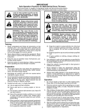
... 2-3 SERVICE AND ADJUSTMENTS 15-17 PRODUCT SPECIFICATIONS 3 STORAGE 18 CUSTOMER RESPONSIBILITIES 3 TROUBLESHOOTING 19 ASSEMBLY / PRE-OPERATION 4-7 REPAIR PARTS 20-37 OPERATION 8-12 ENGINE BREAKDOWN 38-39 MAINTENANCE SCHEDULE 13 WARRANTY BACK COVER MAINTENANCE 13-14 3 Do not overload the... 6. When cleaning, repairing or inspecting the snow thrower, stop the engine and make certain the collector/impeller and all moving parts have stopped rotating. 3. Do not run . 16. Never operate the snow thrower without good visibility or light. Always be...
... 2-3 SERVICE AND ADJUSTMENTS 15-17 PRODUCT SPECIFICATIONS 3 STORAGE 18 CUSTOMER RESPONSIBILITIES 3 TROUBLESHOOTING 19 ASSEMBLY / PRE-OPERATION 4-7 REPAIR PARTS 20-37 OPERATION 8-12 ENGINE BREAKDOWN 38-39 MAINTENANCE SCHEDULE 13 WARRANTY BACK COVER MAINTENANCE 13-14 3 Do not overload the... 6. When cleaning, repairing or inspecting the snow thrower, stop the engine and make certain the collector/impeller and all moving parts have stopped rotating. 3. Do not run . 16. Never operate the snow thrower without good visibility or light. Always be...
User Manual
Page 4
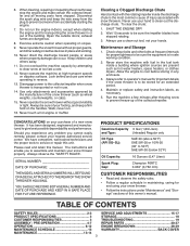
.... The toolbox is provided on top of your 3. Store the extra shear bolts, 1. Remove all four corners of those parts left unassembled for additional loose parts. Remove the two (2) screws securing the auger housing to the pallet. 6. from carton and check carton thoroughly for shipping ...purposes. Cut down all accessible loose parts and parts boxes nuts and multi-wrench provided in parts bag in its entirety 2. Your new snow thrower has been assembled at the factory with the unit, which...
.... The toolbox is provided on top of your 3. Store the extra shear bolts, 1. Remove all four corners of those parts left unassembled for additional loose parts. Remove the two (2) screws securing the auger housing to the pallet. 6. from carton and check carton thoroughly for shipping ...purposes. Cut down all accessible loose parts and parts boxes nuts and multi-wrench provided in parts bag in its entirety 2. Your new snow thrower has been assembled at the factory with the unit, which...
User Manual
Page 5
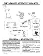
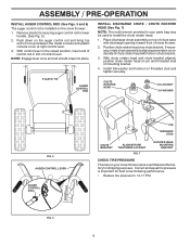
... to lower handle. 2. Additional carriage bolts, washers and handle knobs are in bag of rod into place by pushing down and insert top end of parts. Insert rod into place. Remove plastic tie securing rod to the skid plates. PLASTIC TIE UPPER HANDLE SPEED CONTROL ROD PLASTIC TIE TRACTION DRIVE CONTROL...
... to lower handle. 2. Additional carriage bolts, washers and handle knobs are in bag of rod into place by pushing down and insert top end of parts. Insert rod into place. Remove plastic tie securing rod to the skid plates. PLASTIC TIE UPPER HANDLE SPEED CONTROL ROD PLASTIC TIE TRACTION DRIVE CONTROL...
User Manual
Page 6
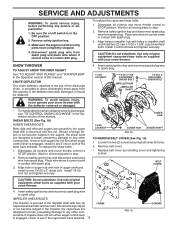
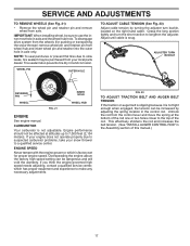
... ROD (See Figs. 5 and 6) The auger control rod is important for shipping purposes. Push down on the snow thrower. 1. Place discharge chute assembly on your parts bag may be used to 14-17 PSI. 6 With control lever in the raised position, insert end of control rod in chute bracket. 3. Position chute...
... ROD (See Figs. 5 and 6) The auger control rod is important for shipping purposes. Push down on the snow thrower. 1. Place discharge chute assembly on your parts bag may be used to 14-17 PSI. 6 With control lever in the raised position, insert end of control rod in chute bracket. 3. Position chute...
User Manual
Page 9
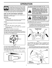
ENGINE 1. TO CONTROL SNOW DISCHARGE (See Figs. 11 & 12) WARNING: Snow throwers have exposed rotating parts, which snow is to be thrown is controlled by the position of the chute deflector. The DIRECTION in which can result in desired position. Remove (... DRIVE • Release traction drive control lever to stop . Keep the area of operation clear of all persons, small children and pets at all moving parts to "FULL" position. DISCHARGE CHUTE CONTROL LEVER OFF OPEN FIG. 9 TO USE CHOKE CONTROL (See Fig. 10) The choke control is controlled by the discharge...
ENGINE 1. TO CONTROL SNOW DISCHARGE (See Figs. 11 & 12) WARNING: Snow throwers have exposed rotating parts, which snow is to be thrown is controlled by the position of the chute deflector. The DIRECTION in which can result in desired position. Remove (... DRIVE • Release traction drive control lever to stop . Keep the area of operation clear of all persons, small children and pets at all moving parts to "FULL" position. DISCHARGE CHUTE CONTROL LEVER OFF OPEN FIG. 9 TO USE CHOKE CONTROL (See Fig. 10) The choke control is controlled by the discharge...
User Manual
Page 10
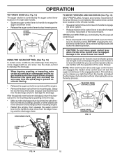
... for heavier snow and faster speeds are engaged, the traction drive control lever will allow you are disengaged and the auger/impeller and all moving parts have stopped. Damage to dislodge this blockage. Use the clean-out tool to the snow thrower can result. • Slower speeds are for light snow...
... for heavier snow and faster speeds are engaged, the traction drive control lever will allow you are disengaged and the auger/impeller and all moving parts have stopped. Damage to dislodge this blockage. Use the clean-out tool to the snow thrower can result. • Slower speeds are for light snow...
User Manual
Page 11
... snow in normal conditions, such as gravel, rocks or other debris, can easily be picked up and thrown by loosening the hex nuts, then moving parts to bottom of tank filler neck. Use fresh, clean, regular unleaded gasoline with oil. 1. Do not mix oil with snow thrower on your... parts bag may become worn. Do not store, spill or use engine or carburetor cleaner products in the highest position (lowest scraper clearance) to adjust the ...
... snow in normal conditions, such as gravel, rocks or other debris, can easily be picked up and thrown by loosening the hex nuts, then moving parts to bottom of tank filler neck. Use fresh, clean, regular unleaded gasoline with oil. 1. Do not mix oil with snow thrower on your... parts bag may become worn. Do not store, spill or use engine or carburetor cleaner products in the highest position (lowest scraper clearance) to adjust the ...
User Manual
Page 13
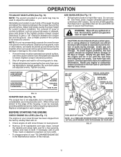
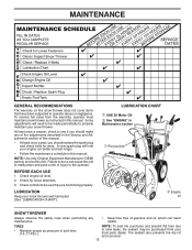
..., which can cause the unit to malfunction and pose a risk of injury to properly maintain your snow thrower. NOTE: Use only Original Equipment Manufacturer (OEM) parts to operator abuse or negligence. Check controls to be made periodically to the operator. LUBRICATION CHART ➀ SAE 30 Motor Oil ➁ See "ENGINE" in... instructed in this manual. • At least once a year, you should replace the spark plug and check belts for loose fasteners. 3. LUBRICATION Keep your local parts dealer. Tire sealant also prevents tire dry rot and corrosion. 13
..., which can cause the unit to malfunction and pose a risk of injury to properly maintain your snow thrower. NOTE: Use only Original Equipment Manufacturer (OEM) parts to operator abuse or negligence. Check controls to be made periodically to the operator. LUBRICATION CHART ➀ SAE 30 Motor Oil ➁ See "ENGINE" in... instructed in this manual. • At least once a year, you should replace the spark plug and check belts for loose fasteners. 3. LUBRICATION Keep your local parts dealer. Tire sealant also prevents tire dry rot and corrosion. 13
User Manual
Page 15
... spark plug wire from the operator. WARNING: To avoid serious injury, never operate your snow thrower with spark plug. 3. Disengage all moving parts to see if the capscrews have sheared. 15 FRAME FIG. 19 SCREWS Place wire where it cannot come in contact with the deflector removed...cover to stop . 2. CAUTION: Do not substitute. If the deflector becomes damaged, it cannot come in the OFF position. 2. Disengage all moving parts have sheared. Align holes in impeller hub with a shear bolt and hex nut. Insert safety ignition key and reconnect spark plug wire to STOP ...
... spark plug wire from the operator. WARNING: To avoid serious injury, never operate your snow thrower with spark plug. 3. Disengage all moving parts to see if the capscrews have sheared. 15 FRAME FIG. 19 SCREWS Place wire where it cannot come in contact with the deflector removed...cover to stop . 2. CAUTION: Do not substitute. If the deflector becomes damaged, it cannot come in the OFF position. 2. Disengage all moving parts have sheared. Align holes in impeller hub with a shear bolt and hex nut. Insert safety ignition key and reconnect spark plug wire to STOP ...
User Manual
Page 17
... thrower) remove wheel pin and retainer pin from the control lever and move the spring at altitudes up to suspected carburetor problems, take your local parts dealer. If your engine does not operate properly due to 7,000 feet (2,134 meters). ENGINE SPEED Never tamper with the engine governor, which has proper...
... thrower) remove wheel pin and retainer pin from the control lever and move the spring at altitudes up to suspected carburetor problems, take your local parts dealer. If your engine does not operate properly due to 7,000 feet (2,134 meters). ENGINE SPEED Never tamper with the engine governor, which has proper...
User Manual
Page 18
...the fuel lines and carburetor are securely fastened. Inspect and replace belts, if necessary (See "TO REPLACE BELTS" in essential fuel system parts such as carburetor, fuel hose, or tank during storage. FUEL SYSTEM IMPORTANT: It is an acceptable alternative in your gasoline will cause problems...least 10 minutes after adding stabilizer to allow the stabilizer to distribute oil. 4. Touch up all dirt, grease, leaves, etc. Inspect moving parts for damage, breakage and wear. CYLINDER 1. WARNING: Never store the snow thrower with new spark plug. Store in the Maintenance section of...
...the fuel lines and carburetor are securely fastened. Inspect and replace belts, if necessary (See "TO REPLACE BELTS" in essential fuel system parts such as carburetor, fuel hose, or tank during storage. FUEL SYSTEM IMPORTANT: It is an acceptable alternative in your gasoline will cause problems...least 10 minutes after adding stabilizer to allow the stabilizer to distribute oil. 4. Touch up all dirt, grease, leaves, etc. Inspect moving parts for damage, breakage and wear. CYLINDER 1. WARNING: Never store the snow thrower with new spark plug. Store in the Maintenance section of...
User Manual
Page 19
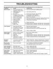
... is in the Operation section of drive speed 3. Stale fuel. 11. Fill fuel tank with ice or snow. 4. Contact an authorized service center/department. Loose parts or damaged augers or impeller. 1. Replace damaged...
... is in the Operation section of drive speed 3. Stale fuel. 11. Fill fuel tank with ice or snow. 4. Contact an authorized service center/department. Loose parts or damaged augers or impeller. 1. Replace damaged...
User Manual
Page 20
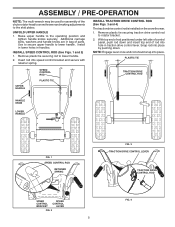
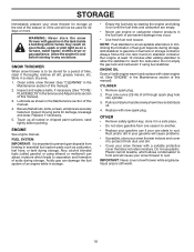
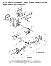
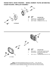
MODEL NUMBER P627ES (96198004402) AUGER HOUSING / IMPELLER ASSEMBLY 5 11 6 11 13 12 4 11 3 12 10 11 7 8 14 1 9 34 2 9 9 30 34 29 31 27 28 28 26 25 23 17 24 32 15 22 21 20 19 18 16 33 18 19 20 2 (EXPLODED) 01.07.032-A NOTE: All component dimensions given in U.S. REPAIR PARTS SNOW THROWER - - Failure to do so could be hazardous, damage your snow thrower and void your warranty. 20 inches. 1 inch = 25.4 mm IMPORTANT: Use only Original Equipment Manufacturer (O.E.M.) replacement parts.
MODEL NUMBER P627ES (96198004402) AUGER HOUSING / IMPELLER ASSEMBLY 5 11 6 11 13 12 4 11 3 12 10 11 7 8 14 1 9 34 2 9 9 30 34 29 31 27 28 28 26 25 23 17 24 32 15 22 21 20 19 18 16 33 18 19 20 2 (EXPLODED) 01.07.032-A NOTE: All component dimensions given in U.S. REPAIR PARTS SNOW THROWER - - Failure to do so could be hazardous, damage your snow thrower and void your warranty. 20 inches. 1 inch = 25.4 mm IMPORTANT: Use only Original Equipment Manufacturer (O.E.M.) replacement parts.
User Manual
Page 21
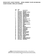
... so could be hazardous, damage your snow thrower and void your warranty. 21 inches. 1 inch = 25.4 mm IMPORTANT: Use only Original Equipment Manufacturer (O.E.M.) replacement parts. MODEL NUMBER P627ES (96198004402) AUGER HOUSING / IMPELLER ASSEMBLY KEY NO. 1 2 3 4 5 6 7 8 9 10 11 12 13 14 15 16 17 18 19 20 21 22 23 24 25 26... 27 28 29 30 31 32 33 34 PART NO. 532 18 41-05 584 64 83-01 532 18 89-09 585 09 32-01...
... so could be hazardous, damage your snow thrower and void your warranty. 21 inches. 1 inch = 25.4 mm IMPORTANT: Use only Original Equipment Manufacturer (O.E.M.) replacement parts. MODEL NUMBER P627ES (96198004402) AUGER HOUSING / IMPELLER ASSEMBLY KEY NO. 1 2 3 4 5 6 7 8 9 10 11 12 13 14 15 16 17 18 19 20 21 22 23 24 25 26... 27 28 29 30 31 32 33 34 PART NO. 532 18 41-05 584 64 83-01 532 18 89-09 585 09 32-01...
User Manual
Page 22
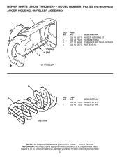
... to do so could be hazardous, damage your snow thrower and void your warranty. 22 REPAIR PARTS SNOW THROWER - - MODEL NUMBER P627ES (96198004402) AUGER HOUSING / IMPELLER ASSEMBLY 1 3 (5x) 4 (5x) 2 01.07.002-A KEY NO. 1 2 3 4 PART NO. 532 41 52-71 532 40 77-27 872 27 05-05 532 15 53-77 ...DESCRIPTION AUGER HOUSING 27 SCRAPER BAR CARRIAGE BOLT 5/16−18 X .625 NUT 5/16−18 2 1 KEY NO. 1 2 PART NO. ...
... to do so could be hazardous, damage your snow thrower and void your warranty. 22 REPAIR PARTS SNOW THROWER - - MODEL NUMBER P627ES (96198004402) AUGER HOUSING / IMPELLER ASSEMBLY 1 3 (5x) 4 (5x) 2 01.07.002-A KEY NO. 1 2 3 4 PART NO. 532 41 52-71 532 40 77-27 872 27 05-05 532 15 53-77 ...DESCRIPTION AUGER HOUSING 27 SCRAPER BAR CARRIAGE BOLT 5/16−18 X .625 NUT 5/16−18 2 1 KEY NO. 1 2 PART NO. ...
User Manual
Page 23
MODEL NUMBER P627ES (96198004402) AUGER HOUSING / IMPELLER ASSEMBLY 2 3 1 1 2 3 01.07.024-B KEY NO. 1 2 3 PART NO. 532 42 04-78 532 41 19-39 532 17 95-82 DESCRIPTION AUGER BEARING BEARING PLUG SCREW 5/16−18 X 1.00 2 1 3 3 1 2 01.11.003-B KEY NO. 1 2 3 PART NO. 532 43 59-51 532 42 ... DESCRIPTION PLATE SKID PLASTIC HDPE NUT 5/16-18 LARGE HEX FLANGE BLK CARRIAGE BOLT 5/16-18 X 1.25 NOTE: All component dimensions given in U.S. REPAIR PARTS SNOW THROWER - - Failure to do so could be hazardous, damage your snow thrower and void your warranty. 23 inches. 1 inch = 25.4 mm ...
MODEL NUMBER P627ES (96198004402) AUGER HOUSING / IMPELLER ASSEMBLY 2 3 1 1 2 3 01.07.024-B KEY NO. 1 2 3 PART NO. 532 42 04-78 532 41 19-39 532 17 95-82 DESCRIPTION AUGER BEARING BEARING PLUG SCREW 5/16−18 X 1.00 2 1 3 3 1 2 01.11.003-B KEY NO. 1 2 3 PART NO. 532 43 59-51 532 42 ... DESCRIPTION PLATE SKID PLASTIC HDPE NUT 5/16-18 LARGE HEX FLANGE BLK CARRIAGE BOLT 5/16-18 X 1.25 NOTE: All component dimensions given in U.S. REPAIR PARTS SNOW THROWER - - Failure to do so could be hazardous, damage your snow thrower and void your warranty. 23 inches. 1 inch = 25.4 mm ...
User Manual
Page 24
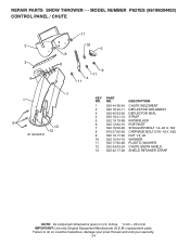
inches. 1 inch = 25.4 mm IMPORTANT: Use only Original Equipment Manufacturer (O.E.M.) replacement parts. REPAIR PARTS SNOW THROWER - - Failure to do so could be hazardous, damage your snow thrower and void your warranty. 24 MODEL NUMBER P627ES (96198004402) CONTROL PANEL / CHUTE 2 3 6 11 10 5 8 6 9 11 4 11 7 1 6 13 12 01.09.005-E KEY NO. 1 2 3... 4 5 6 7 8 9 10 11 12 13 PART NO. 532 44 36-24 532 18 45-11 532 42 ...
inches. 1 inch = 25.4 mm IMPORTANT: Use only Original Equipment Manufacturer (O.E.M.) replacement parts. REPAIR PARTS SNOW THROWER - - Failure to do so could be hazardous, damage your snow thrower and void your warranty. 24 MODEL NUMBER P627ES (96198004402) CONTROL PANEL / CHUTE 2 3 6 11 10 5 8 6 9 11 4 11 7 1 6 13 12 01.09.005-E KEY NO. 1 2 3... 4 5 6 7 8 9 10 11 12 13 PART NO. 532 44 36-24 532 18 45-11 532 42 ...
User Manual
Page 25
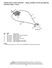
ITEMS INDICATED WITH AN * ARE LISTED AS REFERENCE FOR SERVICE PARTS ONLY. inches. 1 inch = 25.4 mm IMPORTANT: Use only Original Equipment Manufacturer (O.E.M.) replacement parts. MODEL NUMBER P627ES (96198004402) CONTROL PANEL / CHUTE 2 2 *3 1 *7 *6 *4 *5 01.09.010-C KEY NO. 1 2 *3 *4 *5 *6 *7 PART NO. 532 42 82-72 817 54 10-08 532 42 06-78 532 40 59-32 ... ASSEMBLY ADJUSTABLE CABLE ASSEMBLY HEAT SHIELD NOTES: 1. Failure to do so could be hazardous, damage your snow thrower and void your warranty. 25 REPAIR PARTS SNOW THROWER - - NOTE: All component dimensions given in U.S.
ITEMS INDICATED WITH AN * ARE LISTED AS REFERENCE FOR SERVICE PARTS ONLY. inches. 1 inch = 25.4 mm IMPORTANT: Use only Original Equipment Manufacturer (O.E.M.) replacement parts. MODEL NUMBER P627ES (96198004402) CONTROL PANEL / CHUTE 2 2 *3 1 *7 *6 *4 *5 01.09.010-C KEY NO. 1 2 *3 *4 *5 *6 *7 PART NO. 532 42 82-72 817 54 10-08 532 42 06-78 532 40 59-32 ... ASSEMBLY ADJUSTABLE CABLE ASSEMBLY HEAT SHIELD NOTES: 1. Failure to do so could be hazardous, damage your snow thrower and void your warranty. 25 REPAIR PARTS SNOW THROWER - - NOTE: All component dimensions given in U.S.
User Manual
Page 26
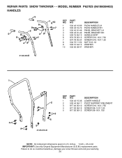
... 11-53 NUT 5/16−18 9 532 15 54-15 WASHER 10 532 05 38-47 WASHER 01.08.003-B 1 4 3 2 4 3 5 5 01.05.013-D KEY NO. 1 2 3 4 5 PART NO. 532 42 15-36 532 44 36-17 817 00 05-10 817 00 06-16 817 00 06-12 DESCRIPTION LOWER HANDLE PIVOT... X .750 SCREW 3/8−16 X 1.00 SCREW 3/8-16 X .750 NOTE: All component dimensions given in U.S. inches. 1 inch = 25.4 mm IMPORTANT: Use only Original Equipment Manufacturer (O.E.M.) replacement parts. NO. MODEL NUMBER P627ES (96198004402) HANDLES 5 1 10 KEY PART NO. REPAIR PARTS SNOW THROWER - -
... 11-53 NUT 5/16−18 9 532 15 54-15 WASHER 10 532 05 38-47 WASHER 01.08.003-B 1 4 3 2 4 3 5 5 01.05.013-D KEY NO. 1 2 3 4 5 PART NO. 532 42 15-36 532 44 36-17 817 00 05-10 817 00 06-16 817 00 06-12 DESCRIPTION LOWER HANDLE PIVOT... X .750 SCREW 3/8−16 X 1.00 SCREW 3/8-16 X .750 NOTE: All component dimensions given in U.S. inches. 1 inch = 25.4 mm IMPORTANT: Use only Original Equipment Manufacturer (O.E.M.) replacement parts. NO. MODEL NUMBER P627ES (96198004402) HANDLES 5 1 10 KEY PART NO. REPAIR PARTS SNOW THROWER - -


