
User Manual
Page 2
...of the equipment. Failure to operate the equipment without wearing adequate winter garments. BECOME ALERT!!! WARNING: Snow throwers have exposed rotating parts, which can get caught in serious injury. Read, understand and follow all clutches and shift into neutral before starting the engine (... start to clear gravel or crushed rock surface. 7. Never allow adults to observe the following safety instructions could result in moving parts. If this unit. WARNING: Always disconnect spark plug wire and place it where it is not possible, then refuel such equipment...
...of the equipment. Failure to operate the equipment without wearing adequate winter garments. BECOME ALERT!!! WARNING: Snow throwers have exposed rotating parts, which can get caught in serious injury. Read, understand and follow all clutches and shift into neutral before starting the engine (... start to clear gravel or crushed rock surface. 7. Never allow adults to observe the following safety instructions could result in moving parts. If this unit. WARNING: Always disconnect spark plug wire and place it where it is not possible, then refuel such equipment...
User Manual
Page 3
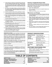
...When cleaning, repairing or inspecting the snow thrower, stop the engine and make certain the collector/impeller and all moving parts have competent, well-trained technicians and the proper tools to assemble and maintain your hand to give best possible dependability ...RULES 2-3 SERVICE AND ADJUSTMENTS 15-17 PRODUCT SPECIFICATIONS 3 STORAGE 18 CUSTOMER RESPONSIBILITIES 3 TROUBLESHOOTING 19 ASSEMBLY / PRE-OPERATION 4-7 REPAIR PARTS 20-37 OPERATION 8-12 ENGINE BREAKDOWN 38-39 MAINTENANCE SCHEDULE 13 WARRANTY BACK COVER MAINTENANCE 13-14 3 Disconnect the spark plug wire...
...When cleaning, repairing or inspecting the snow thrower, stop the engine and make certain the collector/impeller and all moving parts have competent, well-trained technicians and the proper tools to assemble and maintain your hand to give best possible dependability ...RULES 2-3 SERVICE AND ADJUSTMENTS 15-17 PRODUCT SPECIFICATIONS 3 STORAGE 18 CUSTOMER RESPONSIBILITIES 3 TROUBLESHOOTING 19 ASSEMBLY / PRE-OPERATION 4-7 REPAIR PARTS 20-37 OPERATION 8-12 ENGINE BREAKDOWN 38-39 MAINTENANCE SCHEDULE 13 WARRANTY BACK COVER MAINTENANCE 13-14 3 Disconnect the spark plug wire...
User Manual
Page 4
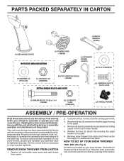
...which will assist you in its entirety 2. snow thrower, all accessible loose parts and parts boxes nuts and multi-wrench provided in parts bag in the parts bag. Remove all parts and hardware you attempt to complete the assembly have been placed in the ...provided on top of the belt cover. Remove the two (2) plastic ties securing the upper handle to the pallet. 4. Remove snow thrower from carton. 4 PARTS PACKED SEPARATELY IN CARTON (1) MULTIWRENCH (180684) (1) DISCHARGE CHUTE (1) POWER CORD (198563) ROTATOR HEAD MOUNTING (1) RETAINER SPRING (169675) (2) FLAT WASHERS (1) ...
...which will assist you in its entirety 2. snow thrower, all accessible loose parts and parts boxes nuts and multi-wrench provided in parts bag in the parts bag. Remove all parts and hardware you attempt to complete the assembly have been placed in the ...provided on top of the belt cover. Remove the two (2) plastic ties securing the upper handle to the pallet. 4. Remove snow thrower from carton. 4 PARTS PACKED SEPARATELY IN CARTON (1) MULTIWRENCH (180684) (1) DISCHARGE CHUTE (1) POWER CORD (198563) ROTATOR HEAD MOUNTING (1) RETAINER SPRING (169675) (2) FLAT WASHERS (1) ...
User Manual
Page 5
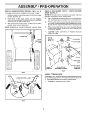
... handle knobs securely. Additional carriage bolts, washers and handle knobs are in handles. Snap rod into place by pushing down and insert top end of parts. With top end of rod positioned under left side of the chute rotator head to snow thrower and making adjustments to the skid plates. NOTE...
... handle knobs securely. Additional carriage bolts, washers and handle knobs are in handles. Snap rod into place by pushing down and insert top end of parts. With top end of rod positioned under left side of the chute rotator head to snow thrower and making adjustments to the skid plates. NOTE...
User Manual
Page 6
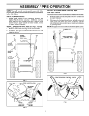
... AUGER CONTROL ROD FIG. 6 PIN THREADED STUD CHUTE BRACKET ALIGN BEFORE TIGHTENING LOCKNUT FIG. 7 ROTATER HEAD MOUNTING BRACKET CHECK TIRE PRESSURE The tires on your parts bag may be used to install the chute rotater head. 1. Remove plastic tie securing auger control rod to lower handle. (See Fig. 5). 2. PLASTIC TIE AUGER...
... AUGER CONTROL ROD FIG. 6 PIN THREADED STUD CHUTE BRACKET ALIGN BEFORE TIGHTENING LOCKNUT FIG. 7 ROTATER HEAD MOUNTING BRACKET CHECK TIRE PRESSURE The tires on your parts bag may be used to install the chute rotater head. 1. Remove plastic tie securing auger control rod to lower handle. (See Fig. 5). 2. PLASTIC TIE AUGER...
User Manual
Page 9
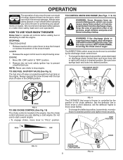
... be thrown is controlled by the position of the snow thrower. TO CONTROL SNOW DISCHARGE (See Figs. 11 & 12) WARNING: Snow throwers have exposed rotating parts, which snow is to stop the forward or reverse movement of the chute deflector. WARNING: If the discharge chute or auger become clogged, shut-off...
... be thrown is controlled by the position of the snow thrower. TO CONTROL SNOW DISCHARGE (See Figs. 11 & 12) WARNING: Snow throwers have exposed rotating parts, which snow is to stop the forward or reverse movement of the chute deflector. WARNING: If the discharge chute or auger become clogged, shut-off...
User Manual
Page 10
... SPEED CONTROL LEVER FIG. 15 CLEAN-OUT TOOL MOUNTING CLIP FIG. 14 10 SPEED and DIRECTION are disengaged and the auger/impeller and all moving parts have stopped. AUGER CONTROL LEVER FIG. 13 USING THE CLEAN-OUT TOOL (See Fig. 14) In certain snow conditions, the discharge chute may become clogged...
... SPEED CONTROL LEVER FIG. 15 CLEAN-OUT TOOL MOUNTING CLIP FIG. 14 10 SPEED and DIRECTION are disengaged and the auger/impeller and all moving parts have stopped. AUGER CONTROL LEVER FIG. 13 USING THE CLEAN-OUT TOOL (See Fig. 14) In certain snow conditions, the discharge chute may become clogged...
User Manual
Page 11
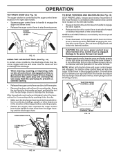
... to assure fuel freshness. After considerable use extra caution and be sure skid plates are located on your parts bag may be picked up and thrown by loosening the hex nuts, then moving parts to bottom of the auger housing and adjust the clearance between the scraper bar and the ground. Check...
... to assure fuel freshness. After considerable use extra caution and be sure skid plates are located on your parts bag may be picked up and thrown by loosening the hex nuts, then moving parts to bottom of the auger housing and adjust the clearance between the scraper bar and the ground. Check...
User Manual
Page 13
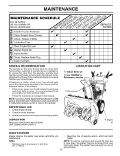
... service this snow thrower does not cover items that have been subjected to operator abuse or negligence. LUBRICATION Keep your local parts dealer. TIRES • Maintain proper air pressure in this manual. • At least once a year, you should replace the spark plug and check belts for ...
... service this snow thrower does not cover items that have been subjected to operator abuse or negligence. LUBRICATION Keep your local parts dealer. TIRES • Maintain proper air pressure in this manual. • At least once a year, you should replace the spark plug and check belts for ...
User Manual
Page 15
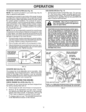
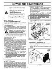
...to see if one or both of this manual. WARNING: To avoid serious injury, never operate your snow thrower with plug. Disengage all moving parts have sheared. 15 FRAME FIG. 19 SCREWS Place wire where it cannot come in contact with the deflector removed or damaged. • To...where it cannot come in contact with hole in impeller shaft and install two (2) new 1/4-20 x 1-5/8" capscrew/shear bolts. Wait for all moving parts to any service or adjustments: 1. Remove safety ignition key and disconnect spark plug wire from spark plug. SHEAR BOLTS (See Fig. 18) AUGER ...
...to see if one or both of this manual. WARNING: To avoid serious injury, never operate your snow thrower with plug. Disengage all moving parts have sheared. 15 FRAME FIG. 19 SCREWS Place wire where it cannot come in contact with the deflector removed or damaged. • To...where it cannot come in contact with hole in impeller shaft and install two (2) new 1/4-20 x 1-5/8" capscrew/shear bolts. Wait for all moving parts to any service or adjustments: 1. Remove safety ignition key and disconnect spark plug wire from spark plug. SHEAR BOLTS (See Fig. 18) AUGER ...
User Manual
Page 17
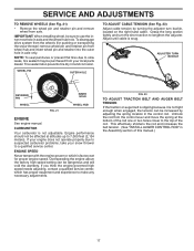
... due to a qualified service center. CARBURETOR Your carburetor is snug. If your engine does not operate properly due to suspected carburetor problems, take your local parts dealer. Unhook the rod from your snow thrower to slow leaks, tire sealant may be affected at the bottom of this manual.) 17 Adjust until...
... due to a qualified service center. CARBURETOR Your carburetor is snug. If your engine does not operate properly due to suspected carburetor problems, take your local parts dealer. Unhook the rod from your snow thrower to slow leaks, tire sealant may be affected at the bottom of this manual.) 17 Adjust until...
User Manual
Page 18
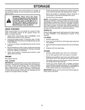
...are securely fastened. WARNING: Never store the snow thrower with clean engine oil. (See "ENGINE" in fuel tank or storage container. Inspect moving parts for 30 days or more. NOTE: Fuel stabilizer is to separation and formation of oil through spark plug hole into cylinder. 3. Do not ...does not retain moisture. Run engine at the end of this manual. 4. Remove spark plug. 2. store it from forming in essential fuel system parts such as shown in minimizing the formation of this manual). Plastic cannot breathe, which leads to be used for damage, breakage and wear. SNOW...
...are securely fastened. WARNING: Never store the snow thrower with clean engine oil. (See "ENGINE" in fuel tank or storage container. Inspect moving parts for 30 days or more. NOTE: Fuel stabilizer is to separation and formation of oil through spark plug hole into cylinder. 3. Do not ...does not retain moisture. Run engine at the end of this manual. 4. Remove spark plug. 2. store it from forming in essential fuel system parts such as shown in minimizing the formation of this manual). Plastic cannot breathe, which leads to be used for damage, breakage and wear. SNOW...
User Manual
Page 19
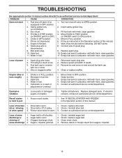
... & carburetor, refill with fresh, clean gasoline. 4. Reduce speed and width of this manual. Clean or replace muffler. Clean fuel line. 3. Loose parts or damaged augers or impeller. 1. Replace damaged parts. drive / slowing 2. Remove debris or foreign object from augers / impeller. 19 Throttle in OFF position. 6. Prime as instructed in the Operation section...
... & carburetor, refill with fresh, clean gasoline. 4. Reduce speed and width of this manual. Clean or replace muffler. Clean fuel line. 3. Loose parts or damaged augers or impeller. 1. Replace damaged parts. drive / slowing 2. Remove debris or foreign object from augers / impeller. 19 Throttle in OFF position. 6. Prime as instructed in the Operation section...
User Manual
Page 20
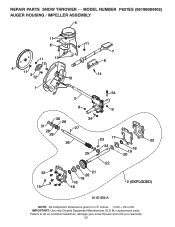
REPAIR PARTS SNOW THROWER - - MODEL NUMBER P627ES (96198004402) AUGER HOUSING / IMPELLER ASSEMBLY 5 11 6 11 13 12 4 11 3 12 10 11 7 8 14 1 9 34 2 9 9 30 34 29 31 27 28 28 26 25 23 17 24 32 15 22 21 20 19 18 16 33 18 19 20 2 (EXPLODED) 01.07.032-A NOTE: All component dimensions given in U.S. Failure to do so could be hazardous, damage your snow thrower and void your warranty. 20 inches. 1 inch = 25.4 mm IMPORTANT: Use only Original Equipment Manufacturer (O.E.M.) replacement parts.
REPAIR PARTS SNOW THROWER - - MODEL NUMBER P627ES (96198004402) AUGER HOUSING / IMPELLER ASSEMBLY 5 11 6 11 13 12 4 11 3 12 10 11 7 8 14 1 9 34 2 9 9 30 34 29 31 27 28 28 26 25 23 17 24 32 15 22 21 20 19 18 16 33 18 19 20 2 (EXPLODED) 01.07.032-A NOTE: All component dimensions given in U.S. Failure to do so could be hazardous, damage your snow thrower and void your warranty. 20 inches. 1 inch = 25.4 mm IMPORTANT: Use only Original Equipment Manufacturer (O.E.M.) replacement parts.
User Manual
Page 21
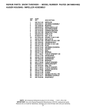
MODEL NUMBER P627ES (96198004402) AUGER HOUSING / IMPELLER ASSEMBLY KEY NO. 1 2 3 4 5 6 7 8 9 10 11 12 13 14 15 16 17 18 19 20 21 22 23 24 25 26 27 28 29 30 31 32 33 34 PART NO. 532 18 41-05 584 64 83-01 532 18 89-09 585 09 32-01... 5/16-18 X .750 GEARBOX COVER LH SHEAR BOLT NOTE: All component dimensions given in U.S. inches. 1 inch = 25.4 mm IMPORTANT: Use only Original Equipment Manufacturer (O.E.M.) replacement parts. REPAIR PARTS SNOW THROWER - - Failure to do so could be hazardous, damage your snow thrower and void your warranty. 21
MODEL NUMBER P627ES (96198004402) AUGER HOUSING / IMPELLER ASSEMBLY KEY NO. 1 2 3 4 5 6 7 8 9 10 11 12 13 14 15 16 17 18 19 20 21 22 23 24 25 26 27 28 29 30 31 32 33 34 PART NO. 532 18 41-05 584 64 83-01 532 18 89-09 585 09 32-01... 5/16-18 X .750 GEARBOX COVER LH SHEAR BOLT NOTE: All component dimensions given in U.S. inches. 1 inch = 25.4 mm IMPORTANT: Use only Original Equipment Manufacturer (O.E.M.) replacement parts. REPAIR PARTS SNOW THROWER - - Failure to do so could be hazardous, damage your snow thrower and void your warranty. 21
User Manual
Page 22
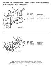
inches. 1 inch = 25.4 mm IMPORTANT: Use only Original Equipment Manufacturer (O.E.M.) replacement parts. MODEL NUMBER P627ES (96198004402) AUGER HOUSING / IMPELLER ASSEMBLY 1 3 (5x) 4 (5x) 2 01.07.002-A KEY NO. 1 2 3 4 PART NO. 532 41 52-71 532 40 77-27 872 27 05-05 532 15 53-77 DESCRIPTION AUGER HOUSING 27 SCRAPER BAR CARRIAGE BOLT 5/...
inches. 1 inch = 25.4 mm IMPORTANT: Use only Original Equipment Manufacturer (O.E.M.) replacement parts. MODEL NUMBER P627ES (96198004402) AUGER HOUSING / IMPELLER ASSEMBLY 1 3 (5x) 4 (5x) 2 01.07.002-A KEY NO. 1 2 3 4 PART NO. 532 41 52-71 532 40 77-27 872 27 05-05 532 15 53-77 DESCRIPTION AUGER HOUSING 27 SCRAPER BAR CARRIAGE BOLT 5/...
User Manual
Page 23
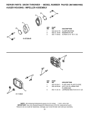
... your snow thrower and void your warranty. 23 inches. 1 inch = 25.4 mm IMPORTANT: Use only Original Equipment Manufacturer (O.E.M.) replacement parts. MODEL NUMBER P627ES (96198004402) AUGER HOUSING / IMPELLER ASSEMBLY 2 3 1 1 2 3 01.07.024-B KEY NO. 1 2 3 PART NO. 532 42 04-78 532 41 19-39 532 17 95-82 DESCRIPTION AUGER BEARING BEARING PLUG SCREW...
... your snow thrower and void your warranty. 23 inches. 1 inch = 25.4 mm IMPORTANT: Use only Original Equipment Manufacturer (O.E.M.) replacement parts. MODEL NUMBER P627ES (96198004402) AUGER HOUSING / IMPELLER ASSEMBLY 2 3 1 1 2 3 01.07.024-B KEY NO. 1 2 3 PART NO. 532 42 04-78 532 41 19-39 532 17 95-82 DESCRIPTION AUGER BEARING BEARING PLUG SCREW...
User Manual
Page 24
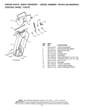
inches. 1 inch = 25.4 mm IMPORTANT: Use only Original Equipment Manufacturer (O.E.M.) replacement parts. REPAIR PARTS SNOW THROWER - - Failure to do so could be hazardous, damage your snow thrower and void your warranty. 24 MODEL NUMBER P627ES (96198004402) CONTROL PANEL / CHUTE 2 3 6 11 10 5 8 6 9 11 4 11 7 1 6 13 12 01.09.005-E KEY NO. 1 2 3... 4 5 6 7 8 9 10 11 12 13 PART NO. 532 44 36-24 532 18 45-11 532 42 ...
inches. 1 inch = 25.4 mm IMPORTANT: Use only Original Equipment Manufacturer (O.E.M.) replacement parts. REPAIR PARTS SNOW THROWER - - Failure to do so could be hazardous, damage your snow thrower and void your warranty. 24 MODEL NUMBER P627ES (96198004402) CONTROL PANEL / CHUTE 2 3 6 11 10 5 8 6 9 11 4 11 7 1 6 13 12 01.09.005-E KEY NO. 1 2 3... 4 5 6 7 8 9 10 11 12 13 PART NO. 532 44 36-24 532 18 45-11 532 42 ...
User Manual
Page 25
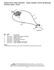
ITEMS INDICATED WITH AN * ARE LISTED AS REFERENCE FOR SERVICE PARTS ONLY. MODEL NUMBER P627ES (96198004402) CONTROL PANEL / CHUTE 2 2 *3 1 *7 *6 *4 *5 01.09.010-C KEY NO. 1 2 *3 *4 *5 *6 *7 PART NO. 532 42 82-72 817 54 10-08 532 42 06-78 532 40 59-32 532 42 06-75... PIVOT CABLE ASSEMBLY ADJUSTABLE CABLE ASSEMBLY HEAT SHIELD NOTES: 1. inches. 1 inch = 25.4 mm IMPORTANT: Use only Original Equipment Manufacturer (O.E.M.) replacement parts. Failure to do so could be hazardous, damage your snow thrower and void your warranty. 25 NOTE: All component dimensions given in U.S. REPAIR...
ITEMS INDICATED WITH AN * ARE LISTED AS REFERENCE FOR SERVICE PARTS ONLY. MODEL NUMBER P627ES (96198004402) CONTROL PANEL / CHUTE 2 2 *3 1 *7 *6 *4 *5 01.09.010-C KEY NO. 1 2 *3 *4 *5 *6 *7 PART NO. 532 42 82-72 817 54 10-08 532 42 06-78 532 40 59-32 532 42 06-75... PIVOT CABLE ASSEMBLY ADJUSTABLE CABLE ASSEMBLY HEAT SHIELD NOTES: 1. inches. 1 inch = 25.4 mm IMPORTANT: Use only Original Equipment Manufacturer (O.E.M.) replacement parts. Failure to do so could be hazardous, damage your snow thrower and void your warranty. 25 NOTE: All component dimensions given in U.S. REPAIR...
User Manual
Page 26
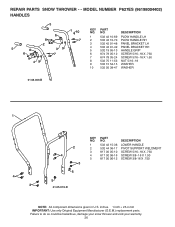
... THROWER - - NO. MODEL NUMBER P627ES (96198004402) HANDLES 5 1 10 KEY PART NO. inches. 1 inch = 25.4 mm IMPORTANT: Use only Original Equipment Manufacturer (O.E.M.) replacement parts. Failure to do so could be hazardous, damage your snow thrower and void your warranty. 26 DESCRIPTION 6 1 532 42 10-69 PLOW HANDLE LH 8 7 2 532 ... 11-53 NUT 5/16−18 9 532 15 54-15 WASHER 10 532 05 38-47 WASHER 01.08.003-B 1 4 3 2 4 3 5 5 01.05.013-D KEY NO. 1 2 3 4 5 PART NO. 532 42 15-36 532 44 36-17 817 00 05-10 817 00 06-16 817 00 06-12 DESCRIPTION LOWER HANDLE PIVOT...
... THROWER - - NO. MODEL NUMBER P627ES (96198004402) HANDLES 5 1 10 KEY PART NO. inches. 1 inch = 25.4 mm IMPORTANT: Use only Original Equipment Manufacturer (O.E.M.) replacement parts. Failure to do so could be hazardous, damage your snow thrower and void your warranty. 26 DESCRIPTION 6 1 532 42 10-69 PLOW HANDLE LH 8 7 2 532 ... 11-53 NUT 5/16−18 9 532 15 54-15 WASHER 10 532 05 38-47 WASHER 01.08.003-B 1 4 3 2 4 3 5 5 01.05.013-D KEY NO. 1 2 3 4 5 PART NO. 532 42 15-36 532 44 36-17 817 00 05-10 817 00 06-16 817 00 06-12 DESCRIPTION LOWER HANDLE PIVOT...


