
User Manual
Page 1
£moe op d • OWNER'S MANUAL MODEL NO. Before you start the engine, read and understand this Owner's Manual. 164744 2.4.98 TR PRINTED IN U.S.A. CHDR500C 5 HP 17 inch Tiller • Assembly • Operation • Customer Responsibilities • Service and Adjustments • Storage • Troubleshooting • Repair Parts Poulan This product has a low emission engine which operates differently from previously built engines.
£moe op d • OWNER'S MANUAL MODEL NO. Before you start the engine, read and understand this Owner's Manual. 164744 2.4.98 TR PRINTED IN U.S.A. CHDR500C 5 HP 17 inch Tiller • Assembly • Operation • Customer Responsibilities • Service and Adjustments • Storage • Troubleshooting • Repair Parts Poulan This product has a low emission engine which operates differently from previously built engines.
User Manual
Page 2
... only attachments and accessories approved by manufacturer). Look behind and use care when backing. • Never allow bystanders near or under rotating parts. • Exercise extreme caution when operating on slippery surfaces. • Handle fuel with the controls and the proper use of instructions....8226; Use an approved fuel container. • Never add fuel to a running (except where specifically recommended by the manufacturer of all moving parts have stopped. If this occurs, let go of trouble. • Stop the engine (motor) when leaving the operating position. •...
... only attachments and accessories approved by manufacturer). Look behind and use care when backing. • Never allow bystanders near or under rotating parts. • Exercise extreme caution when operating on slippery surfaces. • Handle fuel with the controls and the proper use of instructions....8226; Use an approved fuel container. • Never add fuel to a running (except where specifically recommended by the manufacturer of all moving parts have stopped. If this occurs, let go of trouble. • Stop the engine (motor) when leaving the operating position. •...
User Manual
Page 4
...of the authorized dealer from this warranty must return the product to the engine or components parts thereof. Transportation charges for any parts submitted for parts or labor incurred in materials and workmanship. Some areas do not allow the limitation of ... RULES PRODUCT SPECIFICATIONS CUSTOMER RESPONSIBILITIES WARRANTY ASSEMBLY OPERATION 2 3 3,13-15 4 5-7 8-12 MAINTENANCE SCHEDULE SERVICE & ADJUSTMENTS STORAGE TROUBLESHOOTING REPAIR PARTS-TILLER 13 15-18 19 20 21-27 LIMITED WARRANTY The Manufacturer warrants to materials or workmanship. For a period of two (2) years...
...of the authorized dealer from this warranty must return the product to the engine or components parts thereof. Transportation charges for any parts submitted for parts or labor incurred in materials and workmanship. Some areas do not allow the limitation of ... RULES PRODUCT SPECIFICATIONS CUSTOMER RESPONSIBILITIES WARRANTY ASSEMBLY OPERATION 2 3 3,13-15 4 5-7 8-12 MAINTENANCE SCHEDULE SERVICE & ADJUSTMENTS STORAGE TROUBLESHOOTING REPAIR PARTS-TILLER 13 15-18 19 20 21-27 LIMITED WARRANTY The Manufacturer warrants to materials or workmanship. For a period of two (2) years...
User Manual
Page 5
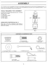
... means when you assemble must be tightened securely. To ensure safe and proper operation of your tiller, all parts and hardware you are listed. (1) Utility knife (1) Tire pressure gauge (1) Pair of those parts left hand is mentioned in the operating position (standing behind tiller handles). Use the correct tools as necessary to...
... means when you assemble must be tightened securely. To ensure safe and proper operation of your tiller, all parts and hardware you are listed. (1) Utility knife (1) Tire pressure gauge (1) Pair of those parts left hand is mentioned in the operating position (standing behind tiller handles). Use the correct tools as necessary to...
User Manual
Page 6
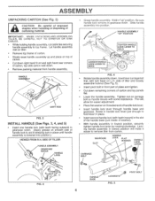
... CAREFUL NOT TO STRETCH OR KINK CABLES. • While holding handle assembly, cut cable ties securing handle assembly to aid in keeping lock in front part of handle lock lever. Be sure handle lock remains in place. Tighten nut on L.H. Insert handle lock lever through handle base and gearcase. ASSEMBLY UNPACKING...
... CAREFUL NOT TO STRETCH OR KINK CABLES. • While holding handle assembly, cut cable ties securing handle assembly to aid in keeping lock in front part of handle lock lever. Be sure handle lock remains in place. Tighten nut on L.H. Insert handle lock lever through handle base and gearcase. ASSEMBLY UNPACKING...
User Manual
Page 11
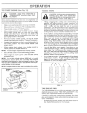
... tiller won't be adjusted for best engine performance. Grasp recoil starter handle with one hand and grasp tiller handle with those shown in the Repair Parts section of this manual). Then go back between passes. When starting engine. NOTE: If at this . however, extremely wet soil will find tilling much easier...
... tiller won't be adjusted for best engine performance. Grasp recoil starter handle with one hand and grasp tiller handle with those shown in the Repair Parts section of this manual). Then go back between passes. When starting engine. NOTE: If at this . however, extremely wet soil will find tilling much easier...
User Manual
Page 19
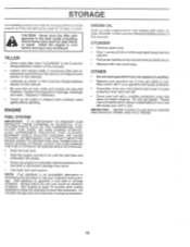
... store the tiller with new spark plug. ENGINE FUEL SYSTEM IMPORTANT: IT IS IMPORTANT TO PREVENT GUM DEPOSITS FROM FORMING IN ESSENTIAL FUEL SYSTEM PARTS SUCH AS THE CARBURETOR, FUEL FILTER, FUEL HOSE, OR TANK DURING STORAGE. OTHER • Do not store gasoline from dust and dirt....; Remove spark plug. • Pour 1 ounce (29 ml) of this manual. • Be sure that does not retain moisture. Inspect moving parts for 30 days or more. sand lightly before storing in any enclosure. Plastic cannot breathe which allows condensation to rust. STORAGE Immediately prepare your tiller...
... store the tiller with new spark plug. ENGINE FUEL SYSTEM IMPORTANT: IT IS IMPORTANT TO PREVENT GUM DEPOSITS FROM FORMING IN ESSENTIAL FUEL SYSTEM PARTS SUCH AS THE CARBURETOR, FUEL FILTER, FUEL HOSE, OR TANK DURING STORAGE. OTHER • Do not store gasoline from dust and dirt....; Remove spark plug. • Pour 1 ounce (29 ml) of this manual. • Be sure that does not retain moisture. Inspect moving parts for 30 days or more. sand lightly before storing in any enclosure. Plastic cannot breathe which allows condensation to rust. STORAGE Immediately prepare your tiller...
User Manual
Page 21
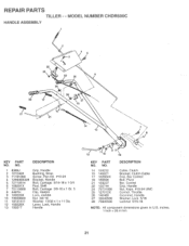
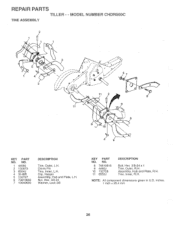
... Lock, Handle 10 73930600 Nut 3/8-16 11 19131611 Washer 13/32 x 1 x 11 Ga. 12 109228X Lever, Lock, Handle 13 150217 Handle o 12 110 9 18 KEY PART NO. MODEL NUMBER CHDR500C HANDLE ASSEMBLY 2 4 5 c 25 24 22 26 6 26 28 17 27 15 21 14 7 13 KEY...
... Lock, Handle 10 73930600 Nut 3/8-16 11 19131611 Washer 13/32 x 1 x 11 Ga. 12 109228X Lever, Lock, Handle 13 150217 Handle o 12 110 9 18 KEY PART NO. MODEL NUMBER CHDR500C HANDLE ASSEMBLY 2 4 5 c 25 24 22 26 6 26 28 17 27 15 21 14 7 13 KEY...
User Manual
Page 22
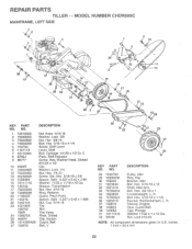
REPAIR PARTS TILLER - - MODEL NUMBER CHDR500C MAINFRAME, LEFT SIDE 3 , 6( 2 '6( 3 l r•z :- 4 NV ,I6 6( 2 j ik----r4A1.1.1 \ \V ' -•k '.•:,..13„
REPAIR PARTS TILLER - - MODEL NUMBER CHDR500C MAINFRAME, LEFT SIDE 3 , 6( 2 '6( 3 l r•z :- 4 NV ,I6 6( 2 j ik----r4A1.1.1 \ \V ' -•k '.•:,..13„
User Manual
Page 23
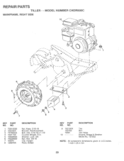
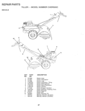
REPAIR PARTS TILLER - - j# • 7/L, / 2 4 3 5 7 6 KEY PART NO. VA .: o/y::: -- --- NO. 9 102190X 150750 795R 10 DESCRIPTION Tire Rim Tire Valve Engine, Briggs & Stratton Model No. 137202 NOTE: All component dimensions given...DESCRIPTION Nut, Keps 5/16-18 Bracket, Reinforcement Bolt, Hex 5/16-18 x 1-1/2 Counter Weight, R.H. Washer, Lock 3/8 Nut, Hex 3/8-16 Clip, Hairpin Rivet, Drilled KEY PART NO. MODEL NUMBER CHDR500C MAINFRAME, RIGHT SIDE 10 J,'• O 9 8 ( ii I, /1 1 . - - - -. ON•. /....s. ....s. --. .. ....S. \ , -S A ••••...
REPAIR PARTS TILLER - - j# • 7/L, / 2 4 3 5 7 6 KEY PART NO. VA .: o/y::: -- --- NO. 9 102190X 150750 795R 10 DESCRIPTION Tire Rim Tire Valve Engine, Briggs & Stratton Model No. 137202 NOTE: All component dimensions given...DESCRIPTION Nut, Keps 5/16-18 Bracket, Reinforcement Bolt, Hex 5/16-18 x 1-1/2 Counter Weight, R.H. Washer, Lock 3/8 Nut, Hex 3/8-16 Clip, Hairpin Rivet, Drilled KEY PART NO. MODEL NUMBER CHDR500C MAINFRAME, RIGHT SIDE 10 J,'• O 9 8 ( ii I, /1 1 . - - - -. ON•. /....s. ....s. --. .. ....S. \ , -S A ••••...
User Manual
Page 24
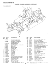
... 22) Gear, Reverse Idler Bearing, Needle Shaft, Reverse Idler Washer, Lock 7/16 Nut, Hex 7/16-20 tearing, Shaft, Ground lye L.H. Oil Gearcase, R.H. REPAIR PARTS TILLER - - w/Bearing (Includes Key No. 4) Gasket, Gearcase Bearing, Needle Washer, Thrust 5/8 x 1.10 x 1/32 Pinion, Input Shaft, Input Bearing, Needle... Washer, Seal Ball, Steel Spring, Shift, Fork O-Ring Arm,. NO. MODEL NUMBER CHDR500C TRANSMISSION r 2 6 5 4 12 13 y 141"41N 14 1110 9 5 7 16 18 23 24\ 25 )%1T* 24 Tv es 24 -- 1 19 2 28 7...
... 22) Gear, Reverse Idler Bearing, Needle Shaft, Reverse Idler Washer, Lock 7/16 Nut, Hex 7/16-20 tearing, Shaft, Ground lye L.H. Oil Gearcase, R.H. REPAIR PARTS TILLER - - w/Bearing (Includes Key No. 4) Gasket, Gearcase Bearing, Needle Washer, Thrust 5/8 x 1.10 x 1/32 Pinion, Input Shaft, Input Bearing, Needle... Washer, Seal Ball, Steel Spring, Shift, Fork O-Ring Arm,. NO. MODEL NUMBER CHDR500C TRANSMISSION r 2 6 5 4 12 13 y 141"41N 14 1110 9 5 7 16 18 23 24\ 25 )%1T* 24 Tv es 24 -- 1 19 2 28 7...
User Manual
Page 25
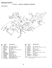
... 10 104085X428 11 73220500 12 10040500 13 72110510 14 124343X 15 161414X428 DESCRIPTION Nut, Flange 5/16-18 Shield, Side, Outer L. REPAIR PARTS TILLER - - inches. 1 inch = 25.4 mm 25 MODEL NUMBER CHDR500C TINE SHIELD 24 24 1 3 5 13 14 ,• • ; • ; -. 'a .0"0* • 2 1 6 7 8 5 9 Y 12 A; , / , , ,•/, 114 • ' :1.01 s :;• . . 4'1 • 14 18 28 6 2 23...
... 10 104085X428 11 73220500 12 10040500 13 72110510 14 124343X 15 161414X428 DESCRIPTION Nut, Flange 5/16-18 Shield, Side, Outer L. REPAIR PARTS TILLER - - inches. 1 inch = 25.4 mm 25 MODEL NUMBER CHDR500C TINE SHIELD 24 24 1 3 5 13 14 ,• • ; • ; -. 'a .0"0* • 2 1 6 7 8 5 9 Y 12 A; , / , , ,•/, 114 • ' :1.01 s :;• . . 4'1 • 14 18 28 6 2 23...
User Manual
Page 26
... x 1 Tine, Outer, R.H. inches. 1 inch = 25.4 mm 26 MODEL NUMBER CHDR500C TINE ASSEMBLY 2 3 • , ft..1..,...,.. - A./......,.*s iiNfe I ,/ •• / 67 4 3 e ir 0 ' Iiy//r-/i -/-,-,,i\,, «I ,' t - 111/ 1 7.4'.... Clip, Hairpin Assembly, Hub and Plate, L.H. Tine, Inner, R.H. NOTE: All component dimensions given in U.S. N2 ,, I 5 . Nut, Hex 3/8-24 Washer, Lock 3/8 KEY PART NO. Assembly, Hub and Plate, R.H. i r- • o'i ""` - ' 2 • •...
... x 1 Tine, Outer, R.H. inches. 1 inch = 25.4 mm 26 MODEL NUMBER CHDR500C TINE ASSEMBLY 2 3 • , ft..1..,...,.. - A./......,.*s iiNfe I ,/ •• / 67 4 3 e ir 0 ' Iiy//r-/i -/-,-,,i\,, «I ,' t - 111/ 1 7.4'.... Clip, Hairpin Assembly, Hub and Plate, L.H. Tine, Inner, R.H. NOTE: All component dimensions given in U.S. N2 ,, I 5 . Nut, Hex 3/8-24 Washer, Lock 3/8 KEY PART NO. Assembly, Hub and Plate, R.H. i r- • o'i ""` - ' 2 • •...
User Manual
Page 27
MODEL NUMBER CHDR500C DECALS t t 3 O 10 4 0 0 0 O 2 o ONe O 6 12 9 C: 5 0 0 O =:1 7 8 1 -o- O O KEY PART NO. REPAIR PARTS TILLER - - i ,-- NO. 1 157384 2 157387 3 157386 4 110678X 5 102180X 6 110614X 7 110612X 8 271948 9 120076X 10 156199 11 273721 12 162384 -- 164744 -- 164745 DESCRIPTION Decal, Logo Decal, Description Decal, Logo Decal, Instruction, Tilling Decal, Shift Indicator Decal, Hand Placement Decal, Caution Decal, Briggs & Stratton Decal, Warning, Rotating Tines Decal, Reverse Decal, 5HP Decal, Warning Till Manual, Owner's (English) Manual, Owner's (French)
MODEL NUMBER CHDR500C DECALS t t 3 O 10 4 0 0 0 O 2 o ONe O 6 12 9 C: 5 0 0 O =:1 7 8 1 -o- O O KEY PART NO. REPAIR PARTS TILLER - - i ,-- NO. 1 157384 2 157387 3 157386 4 110678X 5 102180X 6 110614X 7 110612X 8 271948 9 120076X 10 156199 11 273721 12 162384 -- 164744 -- 164745 DESCRIPTION Decal, Logo Decal, Description Decal, Logo Decal, Instruction, Tilling Decal, Shift Indicator Decal, Hand Placement Decal, Caution Decal, Briggs & Stratton Decal, Warning, Rotating Tines Decal, Reverse Decal, 5HP Decal, Warning Till Manual, Owner's (English) Manual, Owner's (French)


