
User Manual
Page 1
£moe op d • OWNER'S MANUAL MODEL NO. Before you start the engine, read and understand this Owner's Manual. 164744 2.4.98 TR PRINTED IN U.S.A. CHDR500C 5 HP 17 inch Tiller • Assembly • Operation • Customer Responsibilities • Service and Adjustments • Storage • Troubleshooting • Repair Parts Poulan This product has a low emission engine which operates differently from previously built engines.
£moe op d • OWNER'S MANUAL MODEL NO. Before you start the engine, read and understand this Owner's Manual. 164744 2.4.98 TR PRINTED IN U.S.A. CHDR500C 5 HP 17 inch Tiller • Assembly • Operation • Customer Responsibilities • Service and Adjustments • Storage • Troubleshooting • Repair Parts Poulan This product has a low emission engine which operates differently from previously built engines.
User Manual
Page 2
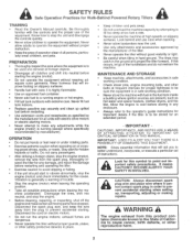
... where the equipment is to be used and remove all foreign objects. • Disengage all clutches and shift into neutral, and stop the engine (motor), remove the wire from the plug to prevent accidental starting . Never fill fuel tank indoors. • Replace gasoline cap securely and clean up , transporting, adjusting or making repairs. Vibration is in safe working condition. • Check shear pins, engine mounting bolts, and other reproductive harm. 2 BECOME...
... where the equipment is to be used and remove all foreign objects. • Disengage all clutches and shift into neutral, and stop the engine (motor), remove the wire from the plug to prevent accidental starting . Never fill fuel tank indoors. • Replace gasoline cap securely and clean up , transporting, adjusting or making repairs. Vibration is in safe working condition. • Check shear pins, engine mounting bolts, and other reproductive harm. 2 BECOME...
User Manual
Page 3
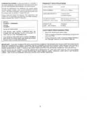
... retain this manual. MODEL NUMBER CHDR500C SERIAL NUMBER DATE OF PURCHASE THE MODEL AND SERIAL NUMBERS WILL BE FOUND ON THE MODEL PLATE ATTACHED TO THE TOP OF THE TRANSMISSION. SAE 5W-30 (Below 32°F/0°C) SPARK PLUG : (GAP: .030"/0.76mm) Champion RJ19LM CUSTOMER RESPONSIBILITIES • Read and observe the safety rules. • Follow a regular schedule in . (206cc) GASOLINE CAPACITY: 3 Quarts (2.8L) Unleaded Regular OIL (API-SF...
... retain this manual. MODEL NUMBER CHDR500C SERIAL NUMBER DATE OF PURCHASE THE MODEL AND SERIAL NUMBERS WILL BE FOUND ON THE MODEL PLATE ATTACHED TO THE TOP OF THE TRANSMISSION. SAE 5W-30 (Below 32°F/0°C) SPARK PLUG : (GAP: .030"/0.76mm) Champion RJ19LM CUSTOMER RESPONSIBILITIES • Read and observe the safety rules. • Follow a regular schedule in . (206cc) GASOLINE CAPACITY: 3 Quarts (2.8L) Unleaded Regular OIL (API-SF...
User Manual
Page 4
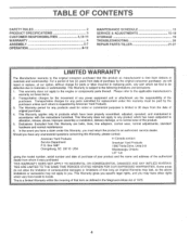
TABLE OF CONTENTS SAFETY RULES PRODUCT SPECIFICATIONS CUSTOMER RESPONSIBILITIES WARRANTY ASSEMBLY OPERATION 2 3 3,13-15 4 5-7 8-12 MAINTENANCE SCHEDULE SERVICE & ADJUSTMENTS STORAGE TROUBLESHOOTING REPAIR PARTS-TILLER 13 15-18 19 20 21-27 LIMITED WARRANTY The Manufacturer warrants to the original consumer purchaser that term as manufactured is free from the date of purchase by the original consumer purchaser, we find to be paid by the...
TABLE OF CONTENTS SAFETY RULES PRODUCT SPECIFICATIONS CUSTOMER RESPONSIBILITIES WARRANTY ASSEMBLY OPERATION 2 3 3,13-15 4 5-7 8-12 MAINTENANCE SCHEDULE SERVICE & ADJUSTMENTS STORAGE TROUBLESHOOTING REPAIR PARTS-TILLER 13 15-18 19 20 21-27 LIMITED WARRANTY The Manufacturer warrants to the original consumer purchaser that term as manufactured is free from the date of purchase by the original consumer purchaser, we find to be paid by the...
User Manual
Page 5
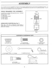
... purposes. OPERATOR'S POSITION FIG. 1 CONTENTS OF HARDWARE PACK (2) Handle Locks 111ffiffik (1) Carriage Bolt 3/8-16 UNC x 1 Grade 5 ...... (1) Center Locknut 3/8-16 UNC 0 CD (1) Flat Washer 13/32 x 1 x 11 Gauge (1) Handle Lock Lever (1) Hairpin Clip h\\1 (1) Pivot Bolt 3/8-16 UNC Grade 5 CD Extra Shear Pins & Clips 5 Use the correct tools as necessary to insure proper tightness. ASSEMBLY Your new tiller has been assembled at the factory with exception of those parts left hand...
... purposes. OPERATOR'S POSITION FIG. 1 CONTENTS OF HARDWARE PACK (2) Handle Locks 111ffiffik (1) Carriage Bolt 3/8-16 UNC x 1 Grade 5 ...... (1) Center Locknut 3/8-16 UNC 0 CD (1) Flat Washer 13/32 x 1 x 11 Gauge (1) Handle Lock Lever (1) Hairpin Clip h\\1 (1) Pivot Bolt 3/8-16 UNC Grade 5 CD Extra Shear Pins & Clips 5 Use the correct tools as necessary to insure proper tightness. ASSEMBLY Your new tiller has been assembled at the factory with exception of those parts left hand...
User Manual
Page 6
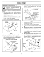
.... (Apply grease on smooth side of handle lock lever. SIDE OF TILLER HANDLE ASSEMBLY GEARCASE NOTCH HANDLE O LOCK Grasp handle assembly. Insert pivot bolt in gearcase notch. Tighten nut on threaded end of handle lock to top frame. Be sure handle lock remains in front part of washer). • With handle assembly in "up and place on L.H. Hold in lowest position, securely tighten handle lock lever by rotating clockwise. Cut down . HANDLE ASSEMBLY SHIFT ROD FIG. 2 INSTALL HANDLE (See...
.... (Apply grease on smooth side of handle lock lever. SIDE OF TILLER HANDLE ASSEMBLY GEARCASE NOTCH HANDLE O LOCK Grasp handle assembly. Insert pivot bolt in gearcase notch. Tighten nut on threaded end of handle lock to top frame. Be sure handle lock remains in front part of washer). • With handle assembly in "up and place on L.H. Hold in lowest position, securely tighten handle lock lever by rotating clockwise. Cut down . HANDLE ASSEMBLY SHIFT ROD FIG. 2 INSTALL HANDLE (See...
User Manual
Page 7
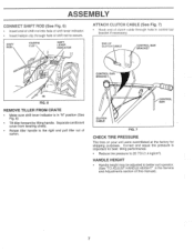
END OF CLUTCH CABLE CONTROL BAR BRACKET N CONTROL BAR BRACKET FIG. 6 REMOVE TILLER FROM CRATE • Make sure shift lever indicator is important for shipping purposes. Separate cardboard cover from leveling shield. • Rotate tiller handle to the right and pull tiller out of shift rod to secure. Correct and equal tire pressure is in "N" position (See Fig. 6) • Tilt tiller forward by lifting handle. ASSEMBLY CONNECT SHIFT ROD (See Fig...
END OF CLUTCH CABLE CONTROL BAR BRACKET N CONTROL BAR BRACKET FIG. 6 REMOVE TILLER FROM CRATE • Make sure shift lever indicator is important for shipping purposes. Separate cardboard cover from leveling shield. • Rotate tiller handle to the right and pull tiller out of shift rod to secure. Correct and equal tire pressure is in "N" position (See Fig. 6) • Tilt tiller forward by lifting handle. ASSEMBLY CONNECT SHIFT ROD (See Fig...
User Manual
Page 8
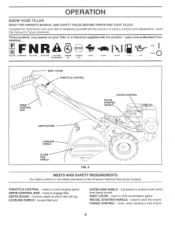
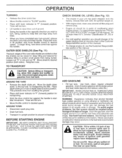
... LEVER - CHOKE CONTROL - OUTER SIDE SHIELD - Used to familiarize yourself with the product. Learn and understand their meaning. Adjustable to start the engine. Used when starting a cold engine. 8 Used to protect small plants from being buried. Controls depth at which tiller will dig. DRIVE CONTROL BAR - Used to engage tiller. Levels tilled soil. RECOIL STARTER HANDLE - Save this manual for future reference. , . • These symbols may appear on your tiller to shift transmission gears. OPERATION KNOW...
... LEVER - CHOKE CONTROL - OUTER SIDE SHIELD - Used to familiarize yourself with the product. Learn and understand their meaning. Adjustable to start the engine. Used when starting a cold engine. 8 Used to protect small plants from being buried. Controls depth at which tiller will dig. DRIVE CONTROL BAR - Used to engage tiller. Levels tilled soil. RECOIL STARTER HANDLE - Save this manual for future reference. , . • These symbols may appear on your tiller to shift transmission gears. OPERATION KNOW...
User Manual
Page 10
... the depth stake pin. Acidic gas can attract moisture which leads to separation and formation of fuel tank to prevent spills and to allow tiller engine and muffler to desired speed. Do not overfill. Drain fuel tank. If gasoline is level. Use fresh fuel next season. CAUTION: Fill to turn . • Move throttle control to desired position (both sides). Disconnect spark plug wire. USE CLEAN OIL AND FUEL AND STORE IN APPROVED, CLEAN, COVERED CONTAINERS. This prevents...
... the depth stake pin. Acidic gas can attract moisture which leads to separation and formation of fuel tank to prevent spills and to allow tiller engine and muffler to desired speed. Do not overfill. Drain fuel tank. If gasoline is level. Use fresh fuel next season. CAUTION: Fill to turn . • Move throttle control to desired position (both sides). Disconnect spark plug wire. USE CLEAN OIL AND FUEL AND STORE IN APPROVED, CLEAN, COVERED CONTAINERS. This prevents...
User Manual
Page 11
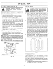
... carburetor fuel mixture may contribute to start actual field use with shear pins (See 'TINE REPLACEMENT" in the Service and Adjustments section of sod or hard ground, apply upward pressure on handle or lower the depth stake. 4 5 6 7 II RECOIL STARTER HANDLE FIG. 13 FIG. 14 TINE SHEAR PINS The tine assemblies on handle. To get through a really tough section of this . OPERATION TO START ENGINE (See Fig. 13) a CAUTION: Keep drive control bar in...
... carburetor fuel mixture may contribute to start actual field use with shear pins (See 'TINE REPLACEMENT" in the Service and Adjustments section of sod or hard ground, apply upward pressure on handle or lower the depth stake. 4 5 6 7 II RECOIL STARTER HANDLE FIG. 13 FIG. 14 TINE SHEAR PINS The tine assemblies on handle. To get through a really tough section of this . OPERATION TO START ENGINE (See Fig. 13) a CAUTION: Keep drive control bar in...
User Manual
Page 13
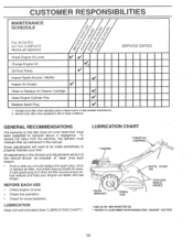
... 44/ Check Engine Oil Level Change Engine Oil Oil Pivot Points V V V1,2, V Inspect Spark Arrester / Muffler V Inspect Air Screen V Clean or Replace Air Cleaner Cartridge 4/ 2 Clean Engine Cylinder Fins V , Replace Spark Plug V 1 - To receive full value from the warranty, the operator must maintain tiller as instructed in the Service and Adjustments section of this manual should be made periodically to operator abuse or negligence. A new spark plug and clean air filter assure proper airfuel mixture and help your tiller. All adjustments in this tiller does not cover items...
... 44/ Check Engine Oil Level Change Engine Oil Oil Pivot Points V V V1,2, V Inspect Spark Arrester / Muffler V Inspect Air Screen V Clean or Replace Air Cleaner Cartridge 4/ 2 Clean Engine Cylinder Fins V , Replace Spark Plug V 1 - To receive full value from the warranty, the operator must maintain tiller as instructed in the Service and Adjustments section of this manual should be made periodically to operator abuse or negligence. A new spark plug and clean air filter assure proper airfuel mixture and help your tiller. All adjustments in this tiller does not cover items...
User Manual
Page 14
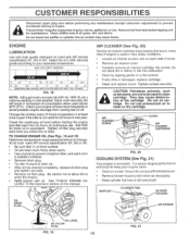
... spark plug wire before performing any maintenance (except carburetor adjustment) to prevent accidental starting of all grass, dirt, and debris. MUFFLER CYLINDER FINS BLOWER HOUSING OIL DRAIN PLUG• AIR SCREEN OIL LEVEL OIL FILLER PLUG FIG. 19 14 0 FIG. 21 Do not allow dirt to enter the engine. • Refill engine with API service classification SF, SG or SH. Check the crankcase oil level before oil change. Prevent fires! Check your expected temperature. See "CHECK ENGINE OIL LEVEL" in a suitable container. • Remove drain plug...
... spark plug wire before performing any maintenance (except carburetor adjustment) to prevent accidental starting of all grass, dirt, and debris. MUFFLER CYLINDER FINS BLOWER HOUSING OIL DRAIN PLUG• AIR SCREEN OIL LEVEL OIL FILLER PLUG FIG. 19 14 0 FIG. 21 Do not allow dirt to enter the engine. • Refill engine with API service classification SF, SG or SH. Check the crankcase oil level before oil change. Prevent fires! Check your expected temperature. See "CHECK ENGINE OIL LEVEL" in a suitable container. • Remove drain plug...
User Manual
Page 15
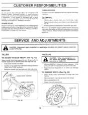
.... SERVICE AND ADJUSTMENTS a CAUTION: Disconnect spark plug wire from wheel. • Remove wheel and tire. • Repair tire and reassemble. Handle height will only require lubrication if serviced. CLEANING Clean engine. Spark plug type and gap setting is sealed and will be different when tiller digs into contact with a spark arrester screen assembly, remove every 50 hours for your unit unless the muffler, air filter and carburetor are seated, overinflation can be positioned at the beginning of all gasoline, oil...
.... SERVICE AND ADJUSTMENTS a CAUTION: Disconnect spark plug wire from wheel. • Remove wheel and tire. • Repair tire and reassemble. Handle height will only require lubrication if serviced. CLEANING Clean engine. Spark plug type and gap setting is sealed and will be different when tiller digs into contact with a spark arrester screen assembly, remove every 50 hours for your unit unless the muffler, air filter and carburetor are seated, overinflation can be positioned at the beginning of all gasoline, oil...
User Manual
Page 17
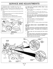
... when drive control bar is engaged. • Tighten cable clip screw securely. ENGINE PULLEY 4-- 1 BELT GUIDE "A" BELT • GUIDE "B" CABLE CLIP SCREW DRIVE CONTROL CABLE SAff t)b) STUD "C" IDLER PULLEY TRANSMISSION PULLEY FIG. 28 17 LESS TENSION 6-, EXTENSION SPRING 5/8" MORE TENSION Pull wheel out from tiller about 5/8 inch (16 mm) stretch is obtained while the drive control bar is in "ENGAGED" position. BELT GUARD CAP NUT AND WASHER 0 HEX NUT AND WASHER (LOCATED BEHIND TIRE) CAP NUT AND WASHER 0 HAIRPIN CLIP AND CLEVIS PIN FIG. 27 TO REPLACE GROUND DRIVE BELT...
... when drive control bar is engaged. • Tighten cable clip screw securely. ENGINE PULLEY 4-- 1 BELT GUIDE "A" BELT • GUIDE "B" CABLE CLIP SCREW DRIVE CONTROL CABLE SAff t)b) STUD "C" IDLER PULLEY TRANSMISSION PULLEY FIG. 28 17 LESS TENSION 6-, EXTENSION SPRING 5/8" MORE TENSION Pull wheel out from tiller about 5/8 inch (16 mm) stretch is obtained while the drive control bar is in "ENGAGED" position. BELT GUARD CAP NUT AND WASHER 0 HEX NUT AND WASHER (LOCATED BEHIND TIRE) CAP NUT AND WASHER 0 HAIRPIN CLIP AND CLEVIS PIN FIG. 27 TO REPLACE GROUND DRIVE BELT...
User Manual
Page 19
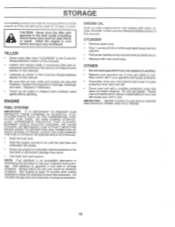
... to another. C`ILINDER • Remove spark plug. • Pour 1 ounce (29 ml) of oil through spark plug hole into cylinder. • Pull starter handle slowly several times to rust. Run engine at the end of this manual). TILLER Clean entire tiller (See "CLEANING" in the Customer Responsibilities section of this manual). • Inspect and replace belts, if necessary (See belt replacement instructions in the Service and Adjustments section of this manual). • Lubricate as shown in...
... to another. C`ILINDER • Remove spark plug. • Pour 1 ounce (29 ml) of oil through spark plug hole into cylinder. • Pull starter handle slowly several times to rust. Run engine at the end of this manual). TILLER Clean entire tiller (See "CLEANING" in the Customer Responsibilities section of this manual). • Inspect and replace belts, if necessary (See belt replacement instructions in the Service and Adjustments section of this manual). • Lubricate as shown in...
User Manual
Page 20
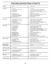
... tilling 1. Engine runs but tiller won't move 1. Throttle control not properly adjusted. 3. Carburetor out of adjustment. 1. Set depth stake for shallower tilling. 2. Engine not "CHOKED" properly. 3. Bad spark plug or improper gap. 9. Oil soaked air filter. CORRECTION 1. See 7O START ENGINE in "FAST" position. 2. Clean or replace air cleaner cartridge, 5. Dirty air cleaner. 3. Loss of fuel. 2. Faulty spark plug. 5. Stale or dirty fuel. 7. Spark plug wire loose. 10. Poor compression. 1. Clean or replace air cleaner cartridge. 3. Check oil level/change oil. 2. Contact...
... tilling 1. Engine runs but tiller won't move 1. Throttle control not properly adjusted. 3. Carburetor out of adjustment. 1. Set depth stake for shallower tilling. 2. Engine not "CHOKED" properly. 3. Bad spark plug or improper gap. 9. Oil soaked air filter. CORRECTION 1. See 7O START ENGINE in "FAST" position. 2. Clean or replace air cleaner cartridge, 5. Dirty air cleaner. 3. Loss of fuel. 2. Faulty spark plug. 5. Stale or dirty fuel. 7. Spark plug wire loose. 10. Poor compression. 1. Clean or replace air cleaner cartridge. 3. Check oil level/change oil. 2. Contact...
User Manual
Page 21
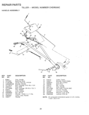
... Lever, Lock, Handle 13 150217 Handle o 12 110 9 18 KEY PART NO. inches. 1 inch = 25.4 mm 21 MODEL NUMBER CHDR500C HANDLE ASSEMBLY 2 4 5 c 25 24 22 26 6 26 28 17 27 15 21 14 7 13 KEY PART NO. NO. 14 159232 15 145821 17 102604X 18 150696 21 159227 22 150744 24 73731000 25 127012X 26 146480 27 10040500 28 73800500 DESCRIPTION Cable, Clutch Bracket, Clutch Cable Grip, Bar Control Bolt...
... Lever, Lock, Handle 13 150217 Handle o 12 110 9 18 KEY PART NO. inches. 1 inch = 25.4 mm 21 MODEL NUMBER CHDR500C HANDLE ASSEMBLY 2 4 5 c 25 24 22 26 6 26 28 17 27 15 21 14 7 13 KEY PART NO. NO. 14 159232 15 145821 17 102604X 18 150696 21 159227 22 150744 24 73731000 25 127012X 26 146480 27 10040500 28 73800500 DESCRIPTION Cable, Clutch Bracket, Clutch Cable Grip, Bar Control Bolt...
User Manual
Page 22
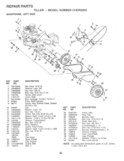
MODEL NUMBER CHDR500C MAINFRAME, LEFT SIDE 3 , 6( 2 '6( 3 l r•z :- 4 NV ,I6 6( 2 j ik----r4A1.1.1 \ \V ' -•k '.•:,..13„ REPAIR PARTS TILLER - -
MODEL NUMBER CHDR500C MAINFRAME, LEFT SIDE 3 , 6( 2 '6( 3 l r•z :- 4 NV ,I6 6( 2 j ik----r4A1.1.1 \ \V ' -•k '.•:,..13„ REPAIR PARTS TILLER - -
User Manual
Page 24
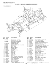
...) Gearcase, L.H. Oil Gearcase, R.H. REPAIR PARTS TILLER - - w/Bearing (Includes Key No. 4) Gasket, Gearcase Bearing, Needle Washer, Thrust 5/8 x 1.10 x 1/32 Pinion, Input Shaft, Input Bearing, Needle Washer, Seal Ball, Steel Spring, Shift, Fork O-Ring Arm,. KEY PART NO. NO. inches 24 1 inch = 25.4 mm w/Bearing (Includes Key No. 8) Shaft, Tine Chain, Roller #50-50 Pitch Screw 1/4-20 x 1/2 Nut, Hex 5/16-18 Kit, Bearing, Tine Shaft Grease, Plastilube #1 NOTE...
...) Gearcase, L.H. Oil Gearcase, R.H. REPAIR PARTS TILLER - - w/Bearing (Includes Key No. 4) Gasket, Gearcase Bearing, Needle Washer, Thrust 5/8 x 1.10 x 1/32 Pinion, Input Shaft, Input Bearing, Needle Washer, Seal Ball, Steel Spring, Shift, Fork O-Ring Arm,. KEY PART NO. NO. inches 24 1 inch = 25.4 mm w/Bearing (Includes Key No. 8) Shaft, Tine Chain, Roller #50-50 Pitch Screw 1/4-20 x 1/2 Nut, Hex 5/16-18 Kit, Bearing, Tine Shaft Grease, Plastilube #1 NOTE...
User Manual
Page 27
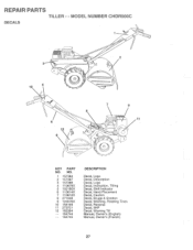
i ,-- REPAIR PARTS TILLER - - O O KEY PART NO. MODEL NUMBER CHDR500C DECALS t t 3 O 10 4 0 0 0 O 2 o ONe O 6 12 9 C: 5 0 0 O =:1 7 8 1 -o- NO. 1 157384 2 157387 3 157386 4 110678X 5 102180X 6 110614X 7 110612X 8 271948 9 120076X 10 156199 11 273721 12 162384 -- 164744 -- 164745 DESCRIPTION Decal, Logo Decal, Description Decal, Logo Decal, Instruction, Tilling Decal, Shift Indicator Decal, Hand Placement Decal, Caution Decal, Briggs & Stratton Decal, Warning, Rotating Tines Decal, Reverse Decal, 5HP Decal, Warning Till Manual, Owner's (English) Manual, Owner's (French)
i ,-- REPAIR PARTS TILLER - - O O KEY PART NO. MODEL NUMBER CHDR500C DECALS t t 3 O 10 4 0 0 0 O 2 o ONe O 6 12 9 C: 5 0 0 O =:1 7 8 1 -o- NO. 1 157384 2 157387 3 157386 4 110678X 5 102180X 6 110614X 7 110612X 8 271948 9 120076X 10 156199 11 273721 12 162384 -- 164744 -- 164745 DESCRIPTION Decal, Logo Decal, Description Decal, Logo Decal, Instruction, Tilling Decal, Shift Indicator Decal, Hand Placement Decal, Caution Decal, Briggs & Stratton Decal, Warning, Rotating Tines Decal, Reverse Decal, 5HP Decal, Warning Till Manual, Owner's (English) Manual, Owner's (French)


