Service Manual
Page 2
... your obsolete outlet. Do not use this product near water. (6) Do not place this product on the power cord. If the product does not operate normally, when the operating instructions are unable to insert the plug into...(0) a. b. If the product exhibits a distinct change in installation unless proper ventilation is damaged or frayed. When the power cord or plug is provided. (8) This product should never be operated from the wall outlet before cleaning. Important Service and... not be placed in a built-in performance, indicating a need for service. . 2 www.polaroid.com
... your obsolete outlet. Do not use this product near water. (6) Do not place this product on the power cord. If the product does not operate normally, when the operating instructions are unable to insert the plug into...(0) a. b. If the product exhibits a distinct change in installation unless proper ventilation is damaged or frayed. When the power cord or plug is provided. (8) This product should never be operated from the wall outlet before cleaning. Important Service and... not be placed in a built-in performance, indicating a need for service. . 2 www.polaroid.com
Service Manual
Page 3
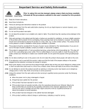
...other grounded connection. • Touch a bare metal surface on the outside of antistatic bags because only the inside an LCD or plasma TV are sensitive to a bare metal part of your workbench or other grounded object before servicing! Unauthorized substitute parts may result ... the overall system. Before servicing the TV, follow these service guidelines: ELECTRIC SHOCK HAZARD Always disconnect AC power before touching any circuit! Never modify any components. Do not lay components on your workbench or other hazards. 3 www.polaroid.com Avoid touching the edge connectors. ...
...other grounded connection. • Touch a bare metal surface on the outside of antistatic bags because only the inside an LCD or plasma TV are sensitive to a bare metal part of your workbench or other grounded object before servicing! Unauthorized substitute parts may result ... the overall system. Before servicing the TV, follow these service guidelines: ELECTRIC SHOCK HAZARD Always disconnect AC power before touching any circuit! Never modify any components. Do not lay components on your workbench or other hazards. 3 www.polaroid.com Avoid touching the edge connectors. ...
Service Manual
Page 4
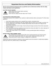
...lead-free solder (Sn-Ag-Cu). When repairing components soldered with the just long enough to confirm a good solder joint. Do not leave the bit powered on the component. Sn e4 - Always clean the soldering bit after every use. (2) Keep the soldering bit in fire, electric shock, or other ...- Because the melting point of solder. Sn alloys with lead-free solder: (1) Always use , clean the bit with steel wool or fine sandpaper. (0) 4 www.polaroid.com Leaving the bit in category e2) e2 - SnZn, SnZnx (no Bi or Zn excluding SnAgCu e3 - When the tip of the soldering bit may...
...lead-free solder (Sn-Ag-Cu). When repairing components soldered with the just long enough to confirm a good solder joint. Do not leave the bit powered on the component. Sn e4 - Always clean the soldering bit after every use. (2) Keep the soldering bit in fire, electric shock, or other ...- Because the melting point of solder. Sn alloys with lead-free solder: (1) Always use , clean the bit with steel wool or fine sandpaper. (0) 4 www.polaroid.com Leaving the bit in category e2) e2 - SnZn, SnZnx (no Bi or Zn excluding SnAgCu e3 - When the tip of the soldering bit may...

Service Manual
Page 6
... Pixel Clock DDC 1/2B Connector Format Level/Impedance DDC 1/2B Sync Frequency Maximum Pixel Clock Connector Format Level / Impedance Format Level / Impedance Format Level / Impedance Power Source Sound Output HDMI DVI 1.0 0.5~3.0Vp-p/100 Ohm (Differential),50 Ohm (Single ending) Single Link Fh = 31~60 kHz Fv = 56~76 Hz 135 MHz...) Y, Pb, Pr or Y, Cb, Cr Y: 1.0Vp-p / 75Ω Pb/Cb, Pr/Cr: 0.7 ± 0.035Vp-p / 75Ω AC100 - 240 V, 60/50 Hz 10W X2, 8 Ohm. 6 www.polaroid.com 1.
... Pixel Clock DDC 1/2B Connector Format Level/Impedance DDC 1/2B Sync Frequency Maximum Pixel Clock Connector Format Level / Impedance Format Level / Impedance Format Level / Impedance Power Source Sound Output HDMI DVI 1.0 0.5~3.0Vp-p/100 Ohm (Differential),50 Ohm (Single ending) Single Link Fh = 31~60 kHz Fv = 56~76 Hz 135 MHz...) Y, Pb, Pr or Y, Cb, Cr Y: 1.0Vp-p / 75Ω Pb/Cb, Pr/Cr: 0.7 ± 0.035Vp-p / 75Ω AC100 - 240 V, 60/50 Hz 10W X2, 8 Ohm. 6 www.polaroid.com 1.
Service Manual
Page 14
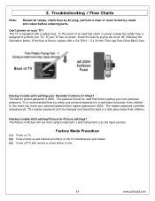
...the safety fuse is designed to exit. 14 www.polaroid.com In the event you keep your TV? The master password overrides all cables, check fuse by prying the cover off TV with a safety fuse. Factory Mode Procedure (1) Power on TV. (2) Press volume up and channel up buttons ... / Flow Charts Note: Reseat all passwords. Having trouble with setting Picture-in a safe place away from children. Can't power on the TV simultaneously and release. (3) Power off , following the illustration below. 3. The master password can't be changed and should be used first before ordering parts....
...the safety fuse is designed to exit. 14 www.polaroid.com In the event you keep your TV? The master password overrides all cables, check fuse by prying the cover off TV with a safety fuse. Factory Mode Procedure (1) Power on TV. (2) Press volume up and channel up buttons ... / Flow Charts Note: Reseat all passwords. Having trouble with setting Picture-in a safe place away from children. Can't power on the TV simultaneously and release. (3) Power off , following the illustration below. 3. The master password can't be changed and should be used first before ordering parts....
Service Manual
Page 20
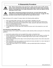
... slide components over any part the TV, make sure the power is OFF, and the power cord is large enough to hold ... This procedure ensures that is removed from their edges. When servicing an LCD or plasma TV, always observe the following safety guidelines: • Wear a grounding ...(ESD) wrist strap, and use them. 6. ELECTROSTATIC DISCHARGE (ESD) Components inside of your workbench or other grounded connection. • Touch a bare metal surface on page 19. Never insert any components. 20 www.polaroid...
... slide components over any part the TV, make sure the power is OFF, and the power cord is large enough to hold ... This procedure ensures that is removed from their edges. When servicing an LCD or plasma TV, always observe the following safety guidelines: • Wear a grounding ...(ESD) wrist strap, and use them. 6. ELECTROSTATIC DISCHARGE (ESD) Components inside of your workbench or other grounded connection. • Touch a bare metal surface on page 19. Never insert any components. 20 www.polaroid...
Service Manual
Page 21
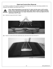
... boards to protect the front bezel and LCD screen from the wall outlet. Use protective cloth between work bench and TV front. A 21 www.polaroid.com Stand and Control Box Removal Lay TV flat on workbench. Never insert any part the TV, make sure the power is OFF, and the power cord is removed from being scratched...
... boards to protect the front bezel and LCD screen from the wall outlet. Use protective cloth between work bench and TV front. A 21 www.polaroid.com Stand and Control Box Removal Lay TV flat on workbench. Never insert any part the TV, make sure the power is OFF, and the power cord is removed from being scratched...

Service Manual
Page 23
.... Allow time for power within all models. Never insert any part the TV, make sure the power is OFF, and the power cord is not damaged. (1) Remove 6 screws (A) from the wall outlet. Note: OEM LCD panels were used in the TV case. Rear Cabinet Cover, LCD Panel and Front Bezel... Note: Before disassembly of any objects into the vent holes in production. A 23 www.polaroid...
.... Allow time for power within all models. Never insert any part the TV, make sure the power is OFF, and the power cord is not damaged. (1) Remove 6 screws (A) from the wall outlet. Note: OEM LCD panels were used in the TV case. Rear Cabinet Cover, LCD Panel and Front Bezel... Note: Before disassembly of any objects into the vent holes in production. A 23 www.polaroid...
Service Manual
Page 28
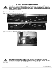
... to the User, on page 19. A (3) Remove 2 screws (A) from the IR Board, and remove the board from the TV. This procedure ensures that the chassis will not cause electric shock. 28 www.polaroid.com Allow time for power within all system boards to discharge before you must follow the steps outlined in the...
... to the User, on page 19. A (3) Remove 2 screws (A) from the IR Board, and remove the board from the TV. This procedure ensures that the chassis will not cause electric shock. 28 www.polaroid.com Allow time for power within all system boards to discharge before you must follow the steps outlined in the...
Service Manual
Page 29
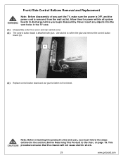
Use alcohol to front bezel. This procedure ensures that the chassis will not cause electric shock. 29 www.polaroid.com Front/Side Control Buttons Removal and Replacement Note: Before disassembly of any objects into the vent holes in the section, Before Returning This Product ... glue to fasten to soften the glue and remove the control button board (A). Never insert any part the TV, make sure the power is OFF, and the power cord is attached with glue. Allow time for power within all system boards to the User, on page 19. Note: Before returning this product to the...
Use alcohol to front bezel. This procedure ensures that the chassis will not cause electric shock. 29 www.polaroid.com Front/Side Control Buttons Removal and Replacement Note: Before disassembly of any objects into the vent holes in the section, Before Returning This Product ... glue to fasten to soften the glue and remove the control button board (A). Never insert any part the TV, make sure the power is OFF, and the power cord is attached with glue. Allow time for power within all system boards to the User, on page 19. Note: Before returning this product to the...
Service Manual
Page 30
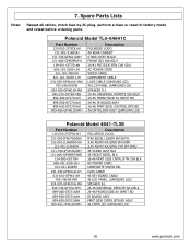
... Lists Note: Reseat all cables, check fuse by AC plug, perform a clear or reset in factory mode and retest before ordering parts. 7. Polaroid Model TLA-04641C Part Number 125-000-375POLAH 151-002-JL468UH 151-700-GF4611UAH 151-A00-GF469RUPH 154-501-GF370-AH 600-181-3200-LIH 621-181-2000JH .../SIDE BTN CVR SILV AC POWER CORD VIDEO CABLE COMPONENT CABLE LVDS CABLE (SAMSUNG L03) 46 LCD PANEL (SAMSUNG L03) SPEAKER R-L 26-46 UNIVERSAL REMOTE SILV/BLK 26-46 FRONT/SIDE AV INPUT BD 26-46 IR BOARD ASSY 26-46 FRNT/SIDE CONTROL BTN BD 46 CNTRL BOX ASSY (SAMSUNG L03) Polaroid Model 4641-TLXB Part Number...
... Lists Note: Reseat all cables, check fuse by AC plug, perform a clear or reset in factory mode and retest before ordering parts. 7. Polaroid Model TLA-04641C Part Number 125-000-375POLAH 151-002-JL468UH 151-700-GF4611UAH 151-A00-GF469RUPH 154-501-GF370-AH 600-181-3200-LIH 621-181-2000JH .../SIDE BTN CVR SILV AC POWER CORD VIDEO CABLE COMPONENT CABLE LVDS CABLE (SAMSUNG L03) 46 LCD PANEL (SAMSUNG L03) SPEAKER R-L 26-46 UNIVERSAL REMOTE SILV/BLK 26-46 FRONT/SIDE AV INPUT BD 26-46 IR BOARD ASSY 26-46 FRNT/SIDE CONTROL BTN BD 46 CNTRL BOX ASSY (SAMSUNG L03) Polaroid Model 4641-TLXB Part Number...

Service Manual
Page 40
TMDS Data 1+ 5. TMDS Data 17. TMDS Data 010. Clock 13. CEC/GND 18. +5V Power 19. Blue Video 4. Sync. TMDS Data 2+ 2. TMDS Data 1 shield 6. Green Video 3. GND 11. TMDS Data 2 shield 3. Hot Plug Detect D-Sub Connector IN. (This function also .... TMDS Data 24. TMDS Data 0+ 8. Green Ground 8. HMDI connector is a type A receptacle for S-video, the pin assignment is described as below: 1: Ground 2: Ground 3: Y 4: C 40 www.polaroid.com CEC 14. DDC CLK 16. SCL For DDC1/2B RCA jacks are all female type. Red Video 2. SDA For DDC1/2B 13. Vdd from...
TMDS Data 1+ 5. TMDS Data 17. TMDS Data 010. Clock 13. CEC/GND 18. +5V Power 19. Blue Video 4. Sync. TMDS Data 2+ 2. TMDS Data 1 shield 6. Green Video 3. GND 11. TMDS Data 2 shield 3. Hot Plug Detect D-Sub Connector IN. (This function also .... TMDS Data 24. TMDS Data 0+ 8. Green Ground 8. HMDI connector is a type A receptacle for S-video, the pin assignment is described as below: 1: Ground 2: Ground 3: Y 4: C 40 www.polaroid.com CEC 14. DDC CLK 16. SCL For DDC1/2B RCA jacks are all female type. Red Video 2. SDA For DDC1/2B 13. Vdd from...

User Guide
Page 4
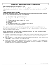
... of procedures other than those specified herein may result in the installation, use, servicing and maintenance of this equipment from the type of power source indicated on the rear of the serial/model plate. ▪ Never overload wall outlets and extensions. 4 The equipment may cause the equipment and cart...
... of procedures other than those specified herein may result in the installation, use, servicing and maintenance of this equipment from the type of power source indicated on the rear of the serial/model plate. ▪ Never overload wall outlets and extensions. 4 The equipment may cause the equipment and cart...
User Guide
Page 5
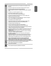
...apparatus, the apparatus has been exposed to rain or moisture, does not operate normally, or has been dropped. ▪ Always remove the power cord from the outlet before cleaning the equipment. ▪ Never use liquid or aerosol cleaners on a surface that is required when the ...to service the equipment yourself. ▪ Opening and removing the covers may void your equipment. ENGLISH Warnings and Precautions ▪ Use and handle the power cord with a soft dry cloth. ▪ Only use attachments/accessories specified by the manufacturer. 5 Never place the equipment : on uneven or ...
...apparatus, the apparatus has been exposed to rain or moisture, does not operate normally, or has been dropped. ▪ Always remove the power cord from the outlet before cleaning the equipment. ▪ Never use liquid or aerosol cleaners on a surface that is required when the ...to service the equipment yourself. ▪ Opening and removing the covers may void your equipment. ENGLISH Warnings and Precautions ▪ Use and handle the power cord with a soft dry cloth. ▪ Only use attachments/accessories specified by the manufacturer. 5 Never place the equipment : on uneven or ...
User Guide
Page 6
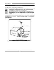
...in wire Ground clamps Electric service equipment Antenna discharge unit (NEC section 810-20) Grounding conductors (NEC section 810-20) Ground clamps Power service grounding (NEC Art250 part H) NEC : National Electrical code EXAMPLE OF OUTDOOR ANTENNA GROUNDING 6 Warnings and Precautions Outdoor Antenna Safety ...9642; An outdoor antenna should not be located in any area where it could come in contact with overhead power lines, or any other electric light or power circuits. ▪ When installing an outdoor antenna system, extreme caution should be taken to prevent contact with...
...in wire Ground clamps Electric service equipment Antenna discharge unit (NEC section 810-20) Grounding conductors (NEC section 810-20) Ground clamps Power service grounding (NEC Art250 part H) NEC : National Electrical code EXAMPLE OF OUTDOOR ANTENNA GROUNDING 6 Warnings and Precautions Outdoor Antenna Safety ...9642; An outdoor antenna should not be located in any area where it could come in contact with overhead power lines, or any other electric light or power circuits. ▪ When installing an outdoor antenna system, extreme caution should be taken to prevent contact with...

User Guide
Page 9
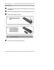
... the Polaroid customer service department. 9 LCD TV Bottom Stand / Screw Driver and Screws 4 ENGLISH Remote Control/ AAA Batteries x 2 SET UP TV CAB/ SAT DVD AUX SLEEP DVD MENU VOL CH PAGE MUTE ASPECT LAST GUIDE LIVE TV PIP MENU OK INFO CC EXIT DVR 1 2 3 ABC DEF 4 5 6 GHI JKL MNO 7 8 9 PQRS TUV WXYZ INPUT . 0 ENTER Power Cord...
... the Polaroid customer service department. 9 LCD TV Bottom Stand / Screw Driver and Screws 4 ENGLISH Remote Control/ AAA Batteries x 2 SET UP TV CAB/ SAT DVD AUX SLEEP DVD MENU VOL CH PAGE MUTE ASPECT LAST GUIDE LIVE TV PIP MENU OK INFO CC EXIT DVR 1 2 3 ABC DEF 4 5 6 GHI JKL MNO 7 8 9 PQRS TUV WXYZ INPUT . 0 ENTER Power Cord...
User Guide
Page 12
... the 2 batteries supplied in the battery compartment. Connect other an external AV device (refer to wall outlet. Connect the AC power cord at the back of the TV and connect the power cord to page19-27). 12 Make sure to open the battery compartment of the batteries with the (+) and ( - ) ...use caustic cleaners (porcelain, stainless steel, toilet, or oven cleaner etc.) on the remote, as it may suffer damage. terminal (refer to the LCD TV's ANT. Chapter 1 Introducing the LCD TV How to setup the TV Use a supplied antenna cable to connect the VHF/UHF signal to page15-17).
... the 2 batteries supplied in the battery compartment. Connect other an external AV device (refer to wall outlet. Connect the AC power cord at the back of the TV and connect the power cord to page19-27). 12 Make sure to open the battery compartment of the batteries with the (+) and ( - ) ...use caustic cleaners (porcelain, stainless steel, toilet, or oven cleaner etc.) on the remote, as it may suffer damage. terminal (refer to the LCD TV's ANT. Chapter 1 Introducing the LCD TV How to setup the TV Use a supplied antenna cable to connect the VHF/UHF signal to page15-17).
User Guide
Page 14
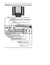
... R Y Pb Pr L COAXIAL L R VIDEO AUDIO VIDEO2 IN S-VIDEO L AUDIO R S-VIDEO IN L R R YPbPr2 IN AUDIO YPbPr1 IN/YPbPr2 IN Connects to the AC power cord. 14 The AUDIO(L/R) of HDMI IN is for DVI connection. VGA IN Connects the PC, or other AV equipment with component(YPbPr) video and...-definition video and two-channel digital audio. Chapter 1 Introducing the LCD TV Rear View and Jacks VIDEO2 IN Connects to receive high/standard definition television. HDTV/TV Air/CABLE VHF/UHF IN TV CABLE/AIR Connects RF input from VHF/UHF antenna or cable to the composite...
... R Y Pb Pr L COAXIAL L R VIDEO AUDIO VIDEO2 IN S-VIDEO L AUDIO R S-VIDEO IN L R R YPbPr2 IN AUDIO YPbPr1 IN/YPbPr2 IN Connects to the AC power cord. 14 The AUDIO(L/R) of HDMI IN is for DVI connection. VGA IN Connects the PC, or other AV equipment with component(YPbPr) video and...-definition video and two-channel digital audio. Chapter 1 Introducing the LCD TV Rear View and Jacks VIDEO2 IN Connects to receive high/standard definition television. HDTV/TV Air/CABLE VHF/UHF IN TV CABLE/AIR Connects RF input from VHF/UHF antenna or cable to the composite...

User Guide
Page 17
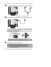
...) that can be attached to a 75-ohm terminal through a 300-75-ohm adapter (not included). 17 ENGLISH Chapter 2 Installing the LCD TV Chapter 2 Installing the LCD TV Refer to the owner's manual of connection that is provided with the various antenna systems. ■ A 75-ohm system is generally a...external equipment to wall outlets until all other connections are more important than those for good color TV reception are completed. The following is a brief explanation of the type of any AC power cords to be connected. F-type connector 75-ohm coaxial cable (round) ■ A ...
...) that can be attached to a 75-ohm terminal through a 300-75-ohm adapter (not included). 17 ENGLISH Chapter 2 Installing the LCD TV Chapter 2 Installing the LCD TV Refer to the owner's manual of connection that is provided with the various antenna systems. ■ A 75-ohm system is generally a...external equipment to wall outlets until all other connections are more important than those for good color TV reception are completed. The following is a brief explanation of the type of any AC power cords to be connected. F-type connector 75-ohm coaxial cable (round) ■ A ...
User Guide
Page 20
...Plastic Prying Tool (Using a metal tool may cause shock) Back of the TV and connect the power cord to replace the fuse. To completely disconnect the main voltage, please remove the power plug from the main voltage when the LCD TV will not be used for a 4A 250V - 5x20mm Time Lag Fuse (Slow... Blow) to wall outlet. In the event of time. If your TV. Chapter 2 Installing the LCD TV Use a supplied antenna cable to connect the TV signal to turn on the LCD TV. Press...
...Plastic Prying Tool (Using a metal tool may cause shock) Back of the TV and connect the power cord to replace the fuse. To completely disconnect the main voltage, please remove the power plug from the main voltage when the LCD TV will not be used for a 4A 250V - 5x20mm Time Lag Fuse (Slow... Blow) to wall outlet. In the event of time. If your TV. Chapter 2 Installing the LCD TV Use a supplied antenna cable to connect the TV signal to turn on the LCD TV. Press...


