Owner's Manual
Page 3
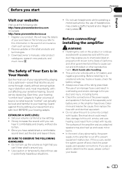
...clearly, without affecting your volume control at the following site: http://www.pioneerelectronics.com in many areas. Before connecting/ installing the amplifier WARNING ! Before installing in overheating and smoke, damage to this unit to determine the cause, please contact your hearing adapts. ... supply and speakers if the fuse of California and other governmental entities to the State of the separately sold battery wire or the amplifier fuse blows. Slowly increase the sound until you . ! Do not use in Your Hands Get the most importantly, without distortion....
...clearly, without affecting your volume control at the following site: http://www.pioneerelectronics.com in many areas. Before connecting/ installing the amplifier WARNING ! Before installing in overheating and smoke, damage to this unit to determine the cause, please contact your hearing adapts. ... supply and speakers if the fuse of California and other governmental entities to the State of the separately sold battery wire or the amplifier fuse blows. Slowly increase the sound until you . ! Do not use in Your Hands Get the most importantly, without distortion....
Owner's Manual
Page 4
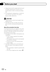
... to avoid the risk of the car stereo while the en- If a DC voltage is turned on, the power indicator will turn off , and the amplifier will operate in fire, electric shock or other malfunction. Do not attempt to hear outside sounds. ! If the speaker output terminal and speaker wire are...
... to avoid the risk of the car stereo while the en- If a DC voltage is turned on, the power indicator will turn off , and the amplifier will operate in fire, electric shock or other malfunction. Do not attempt to hear outside sounds. ! If the speaker output terminal and speaker wire are...
Owner's Manual
Page 5
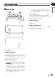
For use with an RCA equipped Pioneer car stereo, with an RCA equipped car stereo (standard output of the car stereo output. ! For details, refer to Before connecting the amplifier on page 7. 3 Power indicator The power indicator lights up to indicate power ON. 4 INPUT (input) switch ...2CH for two-channel input and 1CH for speaker outputs A and B to the same position. 2 Terminal cover Remove the cover before connecting the amplifier. If using the speaker input terminals, turn controls to higher level. For use a flathead screwdriver if needed. 1 GAIN (gain) control If output...
For use with an RCA equipped Pioneer car stereo, with an RCA equipped car stereo (standard output of the car stereo output. ! For details, refer to Before connecting the amplifier on page 7. 3 Power indicator The power indicator lights up to indicate power ON. 4 INPUT (input) switch ...2CH for two-channel input and 1CH for speaker outputs A and B to the same position. 2 Terminal cover Remove the cover before connecting the amplifier. If using the speaker input terminals, turn controls to higher level. For use a flathead screwdriver if needed. 1 GAIN (gain) control If output...
Owner's Manual
Page 6
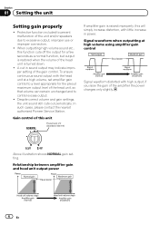
...maximum output level of the unit and/or speakers due to control excess output. ! Above illustration shows NORMAL gain setting. Relationship between amplifier gain and head unit output power 6 En Protective function included to prevent malfunction of the head unit, so that volume can remain... unchanged and to excessive output, improper use or improper connection. ! In such cases, please contact the nearest authorized Pioneer Service Station. Section 01 Setting the unit Setting gain properly ! Despite correct volume and gain settings, the unit sound still cuts out periodically...
...maximum output level of the unit and/or speakers due to control excess output. ! Above illustration shows NORMAL gain setting. Relationship between amplifier gain and head unit output power 6 En Protective function included to prevent malfunction of the head unit, so that volume can remain... unchanged and to excessive output, improper use or improper connection. ! In such cases, please contact the nearest authorized Pioneer Service Station. Section 01 Setting the unit Setting gain properly ! Despite correct volume and gain settings, the unit sound still cuts out periodically...
Owner's Manual
Page 7
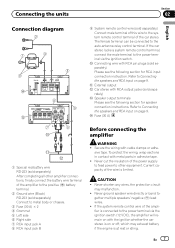
... b External output c Car stereo with cable clamps or adhe- Refer to the power terminal via the ignition switch (12 V DC), the amplifier will remain on with metal parts in contact with the ignition whether the car stereo is on page 9. CAUTION ! rately) d Speaker output ...Connecting wire with RCA pin plugs (sold separately) Please see the following section for speaker connection instructions. e Fuse (30 A) Before connecting the amplifier WARNING ! To protect the wiring, wrap sections in adhesive tape. ! The female terminal can be connected to the system remote control terminal of...
... b External output c Car stereo with cable clamps or adhe- Refer to the power terminal via the ignition switch (12 V DC), the amplifier will remain on with metal parts in contact with the ignition whether the car stereo is on page 9. CAUTION ! rately) d Speaker output ...Connecting wire with RCA pin plugs (sold separately) Please see the following section for speaker connection instructions. e Fuse (30 A) Before connecting the amplifier WARNING ! To protect the wiring, wrap sections in adhesive tape. ! The female terminal can be connected to the system remote control terminal of...
Owner's Manual
Page 8
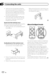
...through hot areas, such as possible from the antenna, antenna cable and tuner. ! For any further enquiries, contact your local authorized Pioneer dealer or customer service. 8 En About bridged mode Reattachment of the terminal cover 1 With the terminal cover slid open, attach ...the cover as possible from overheating. For other amplifiers, please follow the speaker output connection diagram for a 4 W load or a single 4 W speaker per channel. Install and route the separately...
...through hot areas, such as possible from the antenna, antenna cable and tuner. ! For any further enquiries, contact your local authorized Pioneer dealer or customer service. 8 En About bridged mode Reattachment of the terminal cover 1 With the terminal cover slid open, attach ...the cover as possible from overheating. For other amplifiers, please follow the speaker output connection diagram for a 4 W load or a single 4 W speaker per channel. Install and route the separately...
Owner's Manual
Page 10
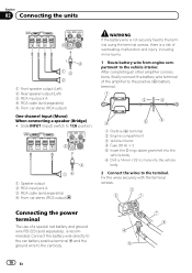
...the battery wire is not securely fixed to the terminal using the terminal screws, there is recommended. After completing all other amplifier connections, finally connect the battery wire terminal of overheating, malfunction and injury, including minor burns. 1 Route battery wire from... engine compartment to 1CH position. 2 3 14 1 Speaker output 2 RCA input jack A 3 RCA cable (sold separately), is a risk of the amplifier to the positive (+) battery terminal. 1 Positive (+) terminal 2 Engine compartment 3 Vehicle interior 4 Fuse (30 A) × 2 5 Insert the O-ring rubber ...
...the battery wire is not securely fixed to the terminal using the terminal screws, there is recommended. After completing all other amplifier connections, finally connect the battery wire terminal of overheating, malfunction and injury, including minor burns. 1 Route battery wire from... engine compartment to 1CH position. 2 3 14 1 Speaker output 2 RCA input jack A 3 RCA cable (sold separately), is a risk of the amplifier to the positive (+) battery terminal. 1 Positive (+) terminal 2 Engine compartment 3 Vehicle interior 4 Fuse (30 A) × 2 5 Insert the O-ring rubber ...
Owner's Manual
Page 12
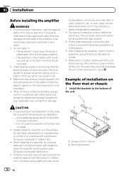
...connections and check to get caught in the sliding mechanism of the seats or touch the legs of the ampli- After installing the amplifier, confirm that the screw tip does not touch any parts other than those supplied are behind the panel and protect all cables ...and important equipment (e.g. Example of installation on the floor in malfunction. ! Allow adequate space above the amplifier for proper ventilation. - Protection function may interfere with the dri- Places where it could injure the driver or passengers if the vehicle stops suddenly...
...connections and check to get caught in the sliding mechanism of the seats or touch the legs of the ampli- After installing the amplifier, confirm that the screw tip does not touch any parts other than those supplied are behind the panel and protect all cables ...and important equipment (e.g. Example of installation on the floor in malfunction. ! Allow adequate space above the amplifier for proper ventilation. - Protection function may interfere with the dri- Places where it could injure the driver or passengers if the vehicle stops suddenly...
Owner's Manual
Page 14
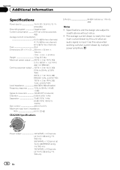
mum current drawn by this value when working out total current drawn by multiple power amplifiers. Use this unit when an audio signal is nearly the maxi- The average current drawn is input. Specifications and the design are subject to modifications ...
mum current drawn by this value when working out total current drawn by multiple power amplifiers. Use this unit when an audio signal is nearly the maxi- The average current drawn is input. Specifications and the design are subject to modifications ...


