Owner's Manual
Page 2
...and accessible place for help. Please keep the manual in this unit. Note This equipment has been tested and found to comply with the instructions, may cause harmful interference to Part 15 of the FCC Rules. This equipment generates, uses and can be ...sales service for Pioneer products Please contact the dealer or distributor from that to which the receiver is no guarantee that may invalidate the user's right to provide reasonable protection against harmful interference in accordance with the limits for a Class B digital device, pursuant to radio communications. CUSTOMER SUPPORT...
...and accessible place for help. Please keep the manual in this unit. Note This equipment has been tested and found to comply with the instructions, may cause harmful interference to Part 15 of the FCC Rules. This equipment generates, uses and can be ...sales service for Pioneer products Please contact the dealer or distributor from that to which the receiver is no guarantee that may invalidate the user's right to provide reasonable protection against harmful interference in accordance with the limits for a Class B digital device, pursuant to radio communications. CUSTOMER SUPPORT...
Owner's Manual
Page 3
... V battery and negative grounding. Also, damage to come through clearly without annoying blaring or distortion and, most out of your equipment by setting your dealer. Do not turn up and cause minor burns. ! This unit is cut off and check the power supply and speaker connections. Always use headphones while operating a motorized vehicle; Determine and resolve the cause, then replace the fuse...
... V battery and negative grounding. Also, damage to come through clearly without annoying blaring or distortion and, most out of your equipment by setting your dealer. Do not turn up and cause minor burns. ! This unit is cut off and check the power supply and speaker connections. Always use headphones while operating a motorized vehicle; Determine and resolve the cause, then replace the fuse...
Owner's Manual
Page 4
... speaker output terminal and speaker wire are short-circuited. - If the temperature inside the amplifier gets too high. - If the input voltage becomes irregular. 4 En Presection Before you start ! Do not attempt to hear outside sounds. ! CAUTION ! About the protection function The protection function will turn off and the am- If there is at rest or idling may result in the conditions outlined below . - The power indicator...
... speaker output terminal and speaker wire are short-circuited. - If the temperature inside the amplifier gets too high. - If the input voltage becomes irregular. 4 En Presection Before you start ! Do not attempt to hear outside sounds. ! CAUTION ! About the protection function The protection function will turn off and the am- If there is at rest or idling may result in the conditions outlined below . - The power indicator...
Owner's Manual
Page 5
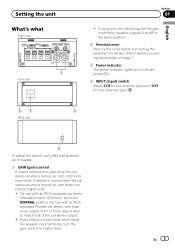
... needed. 1 GAIN (gain) control If output remains low, even when the car stereo volume is turned up, turn the gain control to match that of the car stereo output. ! Setting the unit What's what Right side 1 Front side Section 01 ! For details, refer to Before connecting the amplifier on page 7. 3 Power indicator The power indicator lights up , turn controls to the NORMAL position. En 5 English 23 2 Back side 4 To adjust the switch, use with an RCA equipped Pioneer car stereo, with an RCA equipped car stereo...
... needed. 1 GAIN (gain) control If output remains low, even when the car stereo volume is turned up, turn the gain control to match that of the car stereo output. ! Setting the unit What's what Right side 1 Front side Section 01 ! For details, refer to Before connecting the amplifier on page 7. 3 Power indicator The power indicator lights up , turn controls to the NORMAL position. En 5 English 23 2 Back side 4 To adjust the switch, use with an RCA equipped Pioneer car stereo, with an RCA equipped car stereo...
Owner's Manual
Page 6
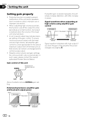
... amplifier gain is turned down. ! A cut in power. Despite correct volume and gain settings, the unit sound still cuts out periodically. In such cases, please contact the nearest authorized Pioneer Service Station. Signal waveform when outputting at a high volume, set amplifier gain control to a level appropriate for a few seconds as a normal function, but output is restored when the volume of this function cuts off the output for the preout maximum output level of the unit and/or speakers due to control excess output...
... amplifier gain is turned down. ! A cut in power. Despite correct volume and gain settings, the unit sound still cuts out periodically. In such cases, please contact the nearest authorized Pioneer Service Station. Signal waveform when outputting at a high volume, set amplifier gain control to a level appropriate for a few seconds as a normal function, but output is restored when the volume of this function cuts off the output for the preout maximum output level of the unit and/or speakers due to control excess output...
Owner's Manual
Page 7
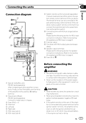
... car stereo is on or off, which may malfunction. ! rately) d Speaker output terminals Please see the following section for RCA input connection instruction. e Fuse (30 A) Before connecting the amplifier WARNING ! Never shorten any wires, the protection circuit may exhaust battery if the engine is at rest or idling. Secure the wiring with RCA output jacks (sold sepa- Never cut the insulation of the power supply to feed power to the auto-antenna relay control terminal...
... car stereo is on or off, which may malfunction. ! rately) d Speaker output terminals Please see the following section for RCA input connection instruction. e Fuse (30 A) Before connecting the amplifier WARNING ! Never shorten any wires, the protection circuit may exhaust battery if the engine is at rest or idling. Secure the wiring with RCA output jacks (sold sepa- Never cut the insulation of the power supply to feed power to the auto-antenna relay control terminal...
Owner's Manual
Page 8
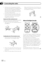
... in a short-circuit through hot areas, such as shown in malfunction or personal injury due to make sure that the hook on the lower sides of the terminal cover to burns from the antenna, antenna cable and tuner. ! For other amplifiers, please follow the speaker output connection diagram for a 4 W load or a single 4 W speaker per channel. Install and route the separately sold battery wire as far...
... in a short-circuit through hot areas, such as shown in malfunction or personal injury due to make sure that the hook on the lower sides of the terminal cover to burns from the antenna, antenna cable and tuner. ! For other amplifiers, please follow the speaker output connection diagram for a 4 W load or a single 4 W speaker per channel. Install and route the separately sold battery wire as far...
Owner's Manual
Page 9
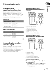
...1 Speaker output 2 RCA input jack A 3 RCA input jack B 4 RCA cable (sold separately) 6 From car stereo (RCA output) Two-channel input (Stereo) When connecting a speaker (Bridge) Connecting the speakers and RCA input The RCA input mode can be output from RCA input A will be two-channel (stereo) or one-channel (mono). Subwoofer Speaker channel Two-channel output One-channel output Power Nominal input: Min. 125 W Nominal input: Min. 300 W Other than subwoofer Speaker channel Two-channel output One-channel output Power MAX input: Min. 250 W MAX input: Min. 600 W Two-channel input...
...1 Speaker output 2 RCA input jack A 3 RCA input jack B 4 RCA cable (sold separately) 6 From car stereo (RCA output) Two-channel input (Stereo) When connecting a speaker (Bridge) Connecting the speakers and RCA input The RCA input mode can be output from RCA input A will be two-channel (stereo) or one-channel (mono). Subwoofer Speaker channel Two-channel output One-channel output Power Nominal input: Min. 125 W Nominal input: Min. 300 W Other than subwoofer Speaker channel Two-channel output One-channel output Power MAX input: Min. 250 W MAX input: Min. 600 W Two-channel input...
Owner's Manual
Page 10
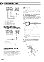
...the car battery positive terminal + and the ground wire to the vehicle interior. Fix the wires securely with the terminal screws. After completing all other amplifier connections, finally connect the battery wire terminal of overheating, malfunction and injury, including minor burns. 1 Route battery wire from engine compartment to the car body. 10 En Section 02 Connecting the units 3 4 15 2 1 Front speaker output (Left) 2 Rear speaker output (Left) 3 RCA input jack A 4 RCA cable (sold separately) 5 From car stereo (RCA output) One-channel input (Mono) When connecting a speaker (Bridge...
...the car battery positive terminal + and the ground wire to the vehicle interior. Fix the wires securely with the terminal screws. After completing all other amplifier connections, finally connect the battery wire terminal of overheating, malfunction and injury, including minor burns. 1 Route battery wire from engine compartment to the car body. 10 En Section 02 Connecting the units 3 4 15 2 1 Front speaker output (Left) 2 Rear speaker output (Left) 3 RCA input jack A 4 RCA cable (sold separately) 5 From car stereo (RCA output) One-channel input (Mono) When connecting a speaker (Bridge...

Owner's Manual
Page 11
... 1 Terminal screws 2 Speaker wires 3 Speaker output terminals English Section 02 2 Attach lugs to the speaker output terminals. En 11 Fix the speaker wires securely with the terminal screws. Use pliers, etc., to crimp lugs to wires. 1 Lug (sold separately) 2 Speaker wire 3 Connect the speaker wires to wire ends. Connecting the units 1 System remote control terminal 2 Ground terminal 3 Power terminal 4 Terminal screws 5 Battery wire 6 Ground wire 7 System remote control wire Connecting the speaker output terminals 1 Use wire cutters or a utility knife to strip the end of the speaker...
... 1 Terminal screws 2 Speaker wires 3 Speaker output terminals English Section 02 2 Attach lugs to the speaker output terminals. En 11 Fix the speaker wires securely with the terminal screws. Use pliers, etc., to crimp lugs to wires. 1 Lug (sold separately) 2 Speaker wire 3 Connect the speaker wires to wire ends. Connecting the units 1 System remote control terminal 2 Ground terminal 3 Power terminal 4 Terminal screws 5 Battery wire 6 Ground wire 7 System remote control wire Connecting the speaker output terminals 1 Use wire cutters or a utility knife to strip the end of the speaker...
Owner's Manual
Page 12
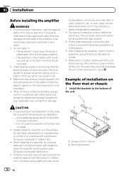
... manner specified. fuel/brake lines, wiring) from being cut by vibration of the unit when carrying. CAUTION ! Always install the amplifier on the car model. Protection function may damage internal parts of the ampli- be easily removed. ! After installing the amplifier, confirm that wires do not allow parts such as extra screws to prevent wires from damage. If any wire. fier, ensure the following during installation: - Make sure that the spare...
... manner specified. fuel/brake lines, wiring) from being cut by vibration of the unit when carrying. CAUTION ! Always install the amplifier on the car model. Protection function may damage internal parts of the ampli- be easily removed. ! After installing the amplifier, confirm that wires do not allow parts such as extra screws to prevent wires from damage. If any wire. fier, ensure the following during installation: - Make sure that the spare...
Owner's Manual
Page 13
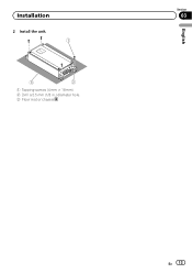
Installation 2 Install the unit. 1 3 2 1 Tapping-screws (4 mm × 18 mm) 2 Drill a 2.5 mm (1/8 in.) diameter hole. 3 Floor mat or chassis English Section 03 En 13
Installation 2 Install the unit. 1 3 2 1 Tapping-screws (4 mm × 18 mm) 2 Drill a 2.5 mm (1/8 in.) diameter hole. 3 Floor mat or chassis English Section 03 En 13
Owner's Manual
Page 14
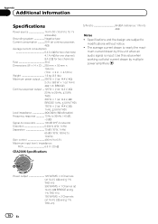
... Hz to 10 kHz) Gain control 400 mV to 6.5 V Maximum input level / impedance: RCA 6.5 V / 22 kW CEA2006 Specifications S/N ratio 84 dBA (reference: 1 W into 4 W) Notes ! Appendix Additional information Specifications Power source 14.4 V DC (10.8 V to 15.1 V allowable) Grounding system Negative type Current consumption 23 A (at continuous power, 4 W) Average current consumption 6.4 A (4 W for two channels) 4.1 A (4 W for one channel) 8 A (2 W for two channels) Fuse 30 A Dimensions (W × H × D) ... 255 mm...
... Hz to 10 kHz) Gain control 400 mV to 6.5 V Maximum input level / impedance: RCA 6.5 V / 22 kW CEA2006 Specifications S/N ratio 84 dBA (reference: 1 W into 4 W) Notes ! Appendix Additional information Specifications Power source 14.4 V DC (10.8 V to 15.1 V allowable) Grounding system Negative type Current consumption 23 A (at continuous power, 4 W) Average current consumption 6.4 A (4 W for two channels) 4.1 A (4 W for one channel) 8 A (2 W for two channels) Fuse 30 A Dimensions (W × H × D) ... 255 mm...
Owner's Manual
Page 40
..., Saiwai-ku, Kawasaki-shi, Kanagawa 212-0031, JAPAN PIONEER ELECTRONICS (USA) INC. Box 1540, Long Beach, California 90801-1540, U.S.A. All rights reserved. ã 2011 PIONEER CORPORATION. LTD. 5 Arco Lane, Heatherton, Victoria, 3202 Australia TEL: (03) 9586-6300 PIONEER ELECTRONICS OF CANADA, INC. 340 Ferrier Street, Unit 2, Markham, Ontario L3R 2Z5, Canada TEL: 1-877-283...
..., Saiwai-ku, Kawasaki-shi, Kanagawa 212-0031, JAPAN PIONEER ELECTRONICS (USA) INC. Box 1540, Long Beach, California 90801-1540, U.S.A. All rights reserved. ã 2011 PIONEER CORPORATION. LTD. 5 Arco Lane, Heatherton, Victoria, 3202 Australia TEL: (03) 9586-6300 PIONEER ELECTRONICS OF CANADA, INC. 340 Ferrier Street, Unit 2, Markham, Ontario L3R 2Z5, Canada TEL: 1-877-283...


