Pioneer PRS-X340 Support and Manuals
Get Help and Manuals for this Pioneer item

View All Support Options Below
Free Pioneer PRS-X340 manuals!
Problems with Pioneer PRS-X340?
Ask a Question
Free Pioneer PRS-X340 manuals!
Problems with Pioneer PRS-X340?
Ask a Question
Popular Pioneer PRS-X340 Manual Pages
Owners Manual - Page 3
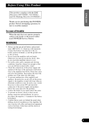
... the car body.
• Do not touch the amplifier with another one of the same size and rating.
• To prevent malfunction of the amplifier. Detect the cause and solve the problem, then replace the fuse with wet hands. Detect the cause and solve the problem.
• Contact the dealer if you for installation of the amplifier and...
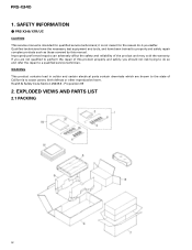
Service Manual - Page 1
... 12 5.
EXPLODED VIEWS AND PARTS LIST 2 3. MAR. 2000 Printed in Japan OPERATIONS AND SPECIFICATIONS 26
PIONEER CORPORATION
4-1, Meguro 1-Chome, Meguro-ku, Tokyo 153-8654, Japan
PIONEER ELECTRONICS SERVICE INC.
CRT2482
X1R/UC,EW
CONTENTS
1. SCHEMATIC DIAGRAM 6 4. PIONEER EUROPE N.V. Service PRS-X340/X1R/UC Manual
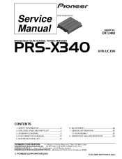
BRIDGEABLE FOUR-CHANNEL POWER AMPLIFIER
PRS-X340
ORDER NO.
Service Manual - Page 2
... repair complex products such as those covered by this product properly and safely; it -yourselfer. If you should not risk trying to perform the repair of this manual. Health & Safety Code Section 25249.6 - you are known to the state of the product and may void the warranty. EXPLODED VIEWS AND PARTS LIST
2.1 PACKING
2 Proposition 65
2. PRS-X340...
Service Manual - Page 3

...to ∇ mark on the product are not in our Master Spare Parts List. - Owner's Manual Model
PRS-X340/X1R/UC PRS-X340/X1R/EW
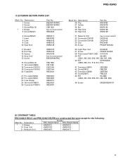
Part No. Mark No. PACKING SECTION PARTS LIST
Part No.
Parts marked by "*" are generally unavailable because they are used
- Description
PRS-X340/X1R/UC PRS-X340/X1R/EW
1 Screw Assy
HEA0047
HEA0047
2 Screw
BYC40P180FZK
BYC40P180FZK
3 Polyethylene Bag...
Service Manual - Page 5
... Connector(CN301)
HKB0002 HKB0006 HKE0012 HKE0020 HKE0030
Mark No. Description
PRS-X340/X1R/UC PRS-X340/X1R/EW
* 4 Badge
HAM0013
HAM0014
14 Amp Unit
HWH0132
HWH0124
31 Network Unit
HWG0018
HWG0017
5 Description
26 Clip 27 Holder 28 Bar 29 Heat Sink 30 Heat Sink
Part No.
HNC0054 HNC0076 HNR0124 HNR0148 HNR0149
31 Network Unit 32 Connector...
Service Manual - Page 6

SCHEMATIC DIAGRAM
3.1 OVERALL CONNECTION DIAGRAM(GUIDE PAGE)
Note: When ordering service parts, be sure to refer to "EXPLODED VIEWS AND PARTS LIST" or "ELECTRICAL PARTS
LIST". 1
2
3
4
PRS-X340
3. A
A-a
Large size
A-a
A-b
SCH diagram
A AMP UNIT
CN851
ISOLATOR GAIN=1
LOW XOVER
B
HP/LP FILTER 12dB/OCTAVE
40-120Hz HIGH XOVER
NETWORK PCB(A) 3k-9kHz
BP FILTER LOW-X TO HIGH-X
...
Service Manual - Page 7

5
IT CB(A) CB(B)
PRS-X340/X1R/EW
5
6
7
8
PRS-X340
A-b
A
AMP GAIN=8.5-33dB
CN301
B
AMP GAIN=8.5-33dB
CN301
C
CN904 CN903 CN902
CN901
D
A7
6
7
8
Service Manual - Page 8

A
B
C
D
PRS-X340
1
8 A-a B C
1
2
2
A AMP UNIT
CN851
ISOLATOR GAIN=1
CN851
RCA OUT GAIN=1
CN851
CN851
CN101 CN102
A-a A-b
LOW XOVER
B
HP/LP FILTER 12dB/OCTAVE
40-120Hz
BP FILTER
HIGH XOVER ...
Service Manual - Page 12

... PCB DIAGRAMS A 1. Viewpoint of PCB diagrams
Connector Capacitor
SIDE A
4CH
†
2CH
P.C.Board B
Chip Part
SIDE B
A AMP UNIT
3
4
C CN104
C
D
A 12
1
2
B CN102
3
4 The parts mounted on this PCB
include all necessary parts for respective destinations, be sure to check with the schematic diagram. 2. For further information for several destination. 1
2
PRS-X340
4.
Service Manual - Page 24

... Idle current should be set when the amplifier has not been run for setting Idle current:
Setting the idle current to Voltage Range. 3.
Specification: Voltage Range:
45 mA ± 5mA 4.0 mV to Voltage Range. 4. Measure voltage across Resistor R436 and set VR501 to Voltage Range.
PRS-X340
6. This adjustment is the instructions for awhile, and set VR502 to the following...
Service Manual - Page 25
....
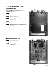
Case(RCA)
Fig.1
Amp Unit
Fig.2 25 Remove the four screws and then remove the Case(Speaker).
Remove the eight screws and then remove the Amp Unit. Remove the two screws
Remove the four screws and then remove the Case(RCA). Removing the Amp Unit (Fig.2)
Remove the two screws.
PRS-X340
- 7. GENERAL INFORMATION
7.1 DISASSEMBLY...
Service Manual - Page 26

OPERATIONS AND SPECIFICATIONS
8.1 OPERATIONS
26 PRS-X340
8.
Service Manual - Page 27

... is HPF-HIGH, you are using with an RCA equipped car stereo (standard output of 500 mV), set the gain controls to the left. For four-channel input, slide this switch to the "NORMAL" position. output of 4 V or more, adjust level to the Pioneer amplifier.
PRS-X340
27
Gain Control
Adjusting the gain controls A and B will...
Service Manual - Page 28

PRS-X340
Connection Diagram
Fuse (30 A) × 2 Grommet
Fuse (30 A) × 2
Special red battery wire [RD-223] (sold separately). Connecting wires with RCA pin plugs (sold separately). System remote control wire (sold separately). If the car... at the amplifier, connect the battery wire terminal of the amplifier to the system remote control terminal of the battery. Car stereo with RCA...
Service Manual - Page 31

... used together with the following manual(s):
Model
Order No.
EXTERIOR SECTION PARTS LIST
Part No.
Mark No. Symbol and Description PRS-X340/X1R/EW PRS-X340/X1H/EW
14 Amp Unit
HWH0124
HWH0156
31 Network Unit
HWG0017
HWG0026
PIONEER CORPORATION
4-1, Meguro 1-Chome, Meguro-ku, Tokyo 153-8654, Japan
PIONEER ELECTRONICS SERVICE INC. This service manual should be used
HXA0364...
Pioneer PRS-X340 Reviews
We have not received any reviews for Pioneer yet.