
Owner's Manual
Page 2
...3 MODE SELECT Switch 3 Bass Boost Frequency Control 3 Bass Boost Level Control 3 Terminal Cover 3 Cut Off Frequency Control for LPF 3 Gain Control 4 BFC (Beat Frequency Control) Switch 4 HEAT Indicator 4 PROTECT Indicator 4 Power Indicator 4 Subsonic Select Switch 4 Setting the Gain properly 5 Connecting the Unit 6 Connection Diagram 7 Solderless Terminal Connections 8 Connecting the Speaker Output Terminals ...... 8 Connecting the Power Terminal 9 Setting the Gain for synced amplifier 10 Connecting the Speaker Wires 10 Installation 15 Attaching the Bass boost remote control...
...3 MODE SELECT Switch 3 Bass Boost Frequency Control 3 Bass Boost Level Control 3 Terminal Cover 3 Cut Off Frequency Control for LPF 3 Gain Control 4 BFC (Beat Frequency Control) Switch 4 HEAT Indicator 4 PROTECT Indicator 4 Power Indicator 4 Subsonic Select Switch 4 Setting the Gain properly 5 Connecting the Unit 6 Connection Diagram 7 Solderless Terminal Connections 8 Connecting the Speaker Output Terminals ...... 8 Connecting the Power Terminal 9 Setting the Gain for synced amplifier 10 Connecting the Speaker Wires 10 Installation 15 Attaching the Bass boost remote control...
Owner's Manual
Page 3
...; Never replace the fuse with one of the same size and rating. • To prevent malfunction of the amplifier and subwoofer, the protective circuit will cut the power supply to the amplifier (sound will keep the volume low enough so that you can cause excessive torque to be sure to disconnect the negative (-) terminal of the battery beforehand. • Confirm that no parts are connected to the RCA input of...
...; Never replace the fuse with one of the same size and rating. • To prevent malfunction of the amplifier and subwoofer, the protective circuit will cut the power supply to the amplifier (sound will keep the volume low enough so that you can cause excessive torque to be sure to disconnect the negative (-) terminal of the battery beforehand. • Confirm that no parts are connected to the RCA input of...

Owner's Manual
Page 4
... "Connection Diagram" section. 3 Cut Off Frequency Control for details on the MODE SELECT switch. Bass Boost Level Control You can select amplifier's sync mode from 40 Hz to the MASTER position when using synchronously connecting two or more of connecting the bass boost remote control to 240 Hz. bridge. When using one amplifier only. When switching to the SYNC INV mode is switched to the SYNC or SYNC INV mode, remove the screw and stopper. See the "Connecting the Speaker Wires...
... "Connection Diagram" section. 3 Cut Off Frequency Control for details on the MODE SELECT switch. Bass Boost Level Control You can select amplifier's sync mode from 40 Hz to the MASTER position when using synchronously connecting two or more of connecting the bass boost remote control to 240 Hz. bridge. When using one amplifier only. When switching to the SYNC INV mode is switched to the SYNC or SYNC INV mode, remove the screw and stopper. See the "Connecting the Speaker Wires...

Owner's Manual
Page 5
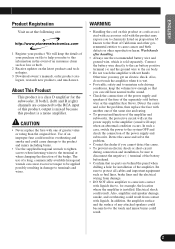
... volume of the car stereo used along with the amplifier. Power Indicator (Blue) The power indicator lights when the power is turned up , turn gain control clockwise. output of 500 mV), set to an AM broadcast with your car stereo, change the BFC switch using with an RCA equipped Pioneer car stereo with the amplifier. PROTECT Indicator (Red) This indicates a problem with this power amplifier is switched on page 17 for details. See the "Troubleshooting" section on page 17 for details. Subsonic Select Switch The subsonic filter cuts inaudible frequencies...
... volume of the car stereo used along with the amplifier. Power Indicator (Blue) The power indicator lights when the power is turned up , turn gain control clockwise. output of 500 mV), set to an AM broadcast with your car stereo, change the BFC switch using with an RCA equipped Pioneer car stereo with the amplifier. PROTECT Indicator (Red) This indicates a problem with this power amplifier is switched on page 17 for details. See the "Troubleshooting" section on page 17 for details. Subsonic Select Switch The subsonic filter cuts inaudible frequencies...
Owner's Manual
Page 6
... sound cuts out from too much output, improper use or improper connection. • When outputting sound at increased volume of this unit may be restored. • If sound output is increased and the power increases only slightly. Signal waveform when outputting at high volume by the gain control of the amplifier to a proper position according to time, contact the nearest authorized PIONEER Service Station. 5 But this function will be improperly set the gain control...
... sound cuts out from too much output, improper use or improper connection. • When outputting sound at increased volume of this unit may be restored. • If sound output is increased and the power increases only slightly. Signal waveform when outputting at high volume by the gain control of the amplifier to a proper position according to time, contact the nearest authorized PIONEER Service Station. 5 But this function will be improperly set the gain control...
Owner's Manual
Page 7
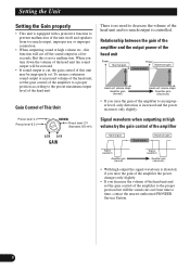
...; This unit is for vehicles with one of whether the car stereo is connected to the product and injury including burns. The amplifier surface could also become damaged. • Install and route the separately sold battery wire, ground wire, speaker wires and the amplifier as far away as possible from the speaker wires. Turn the car stereo off . Use of an improper fuse could result in a short-circuit through the ignition switch...
...; This unit is for vehicles with one of whether the car stereo is connected to the product and injury including burns. The amplifier surface could also become damaged. • Install and route the separately sold battery wire, ground wire, speaker wires and the amplifier as far away as possible from the speaker wires. Turn the car stereo off . Use of an improper fuse could result in a short-circuit through the ignition switch...

Owner's Manual
Page 8
... the car stereo (SYSTEM REMOTE CONTROL). The battery wire, the ground wire and the optional direct Battery ground wire must be same size as the battery wire. Car stereo with RCA pin plugs (sold separately) The ground wires must be turned OFF. Positive (+) terminal Battery wire (sold separately) Connect the male terminal of this jack cannot be connected to the auto-antenna relay control terminal. Connecting the Unit Connection Diagram • In the case of connecting the external output from a car stereo to an RCA input, use the jack used , connect the subwoofer output jack...
... the car stereo (SYSTEM REMOTE CONTROL). The battery wire, the ground wire and the optional direct Battery ground wire must be same size as the battery wire. Car stereo with RCA pin plugs (sold separately) The ground wires must be turned OFF. Positive (+) terminal Battery wire (sold separately) Connect the male terminal of this jack cannot be connected to the auto-antenna relay control terminal. Connecting the Unit Connection Diagram • In the case of connecting the external output from a car stereo to an RCA input, use the jack used , connect the subwoofer output jack...

Owner's Manual
Page 9
... wire ties around the wires. • Wrap the wire tie around the wire insulation, not the stripped wire. • Cut off any excess portions of the wire ties. Wire Size 8 AWG 6 AWG 4 AWG 1. Connecting the Speaker Output Terminals Speaker Wire Size less than 5.2 m less than 8.2 m less than 13.4 m Wire Length less than 44 ft. less than 27 ft. Wire tie 8 However, since excessively tightening the terminal screw of the System remote control...
... wire ties around the wires. • Wrap the wire tie around the wire insulation, not the stripped wire. • Cut off any excess portions of the wire ties. Wire Size 8 AWG 6 AWG 4 AWG 1. Connecting the Speaker Output Terminals Speaker Wire Size less than 5.2 m less than 8.2 m less than 13.4 m Wire Length less than 44 ft. less than 27 ft. Wire tie 8 However, since excessively tightening the terminal screw of the System remote control...

Owner's Manual
Page 10
... the wires to 20 AWG wire for the system remote control wire. System remote control terminal Power terminal Battery wire Terminal screw Terminal screw GND terminal System remote control wire Ground wire WARNING Failure to securely fasten the battery wire to the terminal using nippers or a cutter. • Battery wire, ground wire: 18 mm to 20 mm (3/4 in.) • System remote control wire: 14 mm to the car body. • Recommended wires size (AWG: American Wire Gauge) is sold separately. Connect the battery wire directly to the car battery positive terminal (+) and the ground wire to...
... the wires to 20 AWG wire for the system remote control wire. System remote control terminal Power terminal Battery wire Terminal screw Terminal screw GND terminal System remote control wire Ground wire WARNING Failure to securely fasten the battery wire to the terminal using nippers or a cutter. • Battery wire, ground wire: 18 mm to 20 mm (3/4 in.) • System remote control wire: 14 mm to the car body. • Recommended wires size (AWG: American Wire Gauge) is sold separately. Connect the battery wire directly to the car battery positive terminal (+) and the ground wire to...
Owner's Manual
Page 11
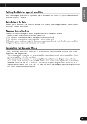
.... 1. Connecting the Speaker Wires Connect the speaker leads and set to measure the master amplifier's output voltage level. 3. Advanced Setup of the Gain Set each amplifier in combination, set the gain control, subsonic select switch, cut off frequency control for the gain control are inactive on an amplifier which has been set MODE SELECT switch to suit the configuration according to measure the synced amplifier's output voltage level. 4. Use volt meter to SYNC or SYNC INV. These settings except for LPF and bass boost control...
.... 1. Connecting the Speaker Wires Connect the speaker leads and set to measure the master amplifier's output voltage level. 3. Advanced Setup of the Gain Set each amplifier in combination, set the gain control, subsonic select switch, cut off frequency control for the gain control are inactive on an amplifier which has been set MODE SELECT switch to suit the configuration according to measure the synced amplifier's output voltage level. 4. Use volt meter to SYNC or SYNC INV. These settings except for LPF and bass boost control...

Owner's Manual
Page 12
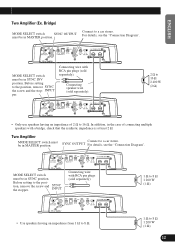
... NOT install or use this amplifier by wiring speakers rated at 2 Ω (or lower) in parallel with Left + and Right - (Diagram A) or use a bridged mode and achieve a 2 Ω load, wire two 4 Ω speakers in parallel to 8 Ω 1 200 W (1 Ω) 11 In addition, refer to a car stereo. For details, see the "Connection Diagram". • Use speakers having an impedance from improper bridging. Proper Amplifier Diagram B - To properly install or use a single 2 Ω speaker. Connect to the speaker instruction manual...
... NOT install or use this amplifier by wiring speakers rated at 2 Ω (or lower) in parallel with Left + and Right - (Diagram A) or use a bridged mode and achieve a 2 Ω load, wire two 4 Ω speakers in parallel to 8 Ω 1 200 W (1 Ω) 11 In addition, refer to a car stereo. For details, see the "Connection Diagram". • Use speakers having an impedance from improper bridging. Proper Amplifier Diagram B - To properly install or use a single 2 Ω speaker. Connect to the speaker instruction manual...
Owner's Manual
Page 13
.... INPUT Connecting wire with RCA pin plugs (sold separately). 1 Ω to 8 Ω 1 200 W (1 Ω) • Use speakers having an impedance of connecting multiple speakers with RCA pin plugs (sold separately). 2 Ω to 16 Ω 2 400 W (2 Ω) • Only use speakers having an impedance from 1 Ω to 8 Ω. 1 Ω to 16 Ω. SYNC OUTPUT For details, see the "Connection Diagram". Connecting speaker wire (sold separately). Before setting to a car stereo. Before setting to a car stereo. MODE SELECT switch...
.... INPUT Connecting wire with RCA pin plugs (sold separately). 1 Ω to 8 Ω 1 200 W (1 Ω) • Use speakers having an impedance of connecting multiple speakers with RCA pin plugs (sold separately). 2 Ω to 16 Ω 2 400 W (2 Ω) • Only use speakers having an impedance from 1 Ω to 8 Ω. 1 Ω to 16 Ω. SYNC OUTPUT For details, see the "Connection Diagram". Connecting speaker wire (sold separately). Before setting to a car stereo. Before setting to a car stereo. MODE SELECT switch...

Owner's Manual
Page 14
... INPUT • Only use speakers having an impedance of connecting multiple speakers with RCA pin plugs (sold separately). Connecting speaker wire (sold separately). MODE SELECT switch must be in the case of 2 Ω to a car stereo. Before setting to the position, remove the screw and the stopper. In addition, in SYNC INV position. Before setting to the position, remove the screw and the stopper. Connecting the Unit Four Amplifier (Ex. Before setting...
... INPUT • Only use speakers having an impedance of connecting multiple speakers with RCA pin plugs (sold separately). Connecting speaker wire (sold separately). MODE SELECT switch must be in the case of 2 Ω to a car stereo. Before setting to the position, remove the screw and the stopper. In addition, in SYNC INV position. Before setting to the position, remove the screw and the stopper. Connecting the Unit Four Amplifier (Ex. Before setting...

Owner's Manual
Page 15
... INPUT • Use speakers having an impedance from 1 Ω to 8 Ω. 1 Ω to 8 Ω 1 200 W (1 Ω) 1 Ω to 8 Ω 1 200 W (1 Ω) 1 Ω to 8 Ω 1 200 W (1 Ω) 1 Ω to a car stereo. SYNC OUTPUT Connecting wire with RCA pin plugs (sold separately). Before setting to the position, remove the screw and the stopper. Four Amplifier MODE SELECT switch must be in SYNC position. For details, see the "Connection Diagram...
... INPUT • Use speakers having an impedance from 1 Ω to 8 Ω. 1 Ω to 8 Ω 1 200 W (1 Ω) 1 Ω to 8 Ω 1 200 W (1 Ω) 1 Ω to 8 Ω 1 200 W (1 Ω) 1 Ω to a car stereo. SYNC OUTPUT Connecting wire with RCA pin plugs (sold separately). Before setting to the position, remove the screw and the stopper. Four Amplifier MODE SELECT switch must be in SYNC position. For details, see the "Connection Diagram...
Owner's Manual
Page 16
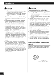
... the amplifier is installed. Attaching the Bass boost remote control Attach with one of any wire. This is important to prevent wires from damage. • Install tapping screws in such a way that the screw tip does not touch any attached speakers could become loose causing the amplifier to shut down. • Never replace the fuse with tapping screws (3 mm × 10 mm) at a sufficiently rigid location. • Make temporary connections...
... the amplifier is installed. Attaching the Bass boost remote control Attach with one of any wire. This is important to prevent wires from damage. • Install tapping screws in such a way that the screw tip does not touch any attached speakers could become loose causing the amplifier to shut down. • Never replace the fuse with tapping screws (3 mm × 10 mm) at a sufficiently rigid location. • Make temporary connections...

Owner's Manual
Page 17
... the screw holes. Replacing the terminal cover 1. Screw Badge 16 Align the unit and terminal cover, and insert the screw. 2. Change the direction of badge, and then tighten the screws with a 4 mm hexagonal wrench. Place the amplifier where it is to be installed. To remove the badge, loose screws by using a 2 mm hexagonal wrench. 2. Drill 2.5 mm (1/8 in .) diameter hole Changing the Direction of installation on...
... the screw holes. Replacing the terminal cover 1. Screw Badge 16 Align the unit and terminal cover, and insert the screw. 2. Change the direction of badge, and then tighten the screws with a 4 mm hexagonal wrench. Place the amplifier where it is to be installed. To remove the badge, loose screws by using a 2 mm hexagonal wrench. 2. Drill 2.5 mm (1/8 in .) diameter hole Changing the Direction of installation on...

Owner's Manual
Page 18
... installed (see the "WARNING" section on . When this happens, immediately discontinue use of the amplifier and check the wiring (see the "WARNING" section on page 2). This is not a malfunction. Contact your dealer if the problem is still not corrected. 17 PROTECT Indicator • This indicator either flashes or lights up in the amplifier. Additional information Troubleshooting The following indicators light momentarily when the amplifier is turned...
... installed (see the "WARNING" section on . When this happens, immediately discontinue use of the amplifier and check the wiring (see the "WARNING" section on page 2). This is not a malfunction. Contact your dealer if the problem is still not corrected. 17 PROTECT Indicator • This indicator either flashes or lights up in the amplifier. Additional information Troubleshooting The following indicators light momentarily when the amplifier is turned...
Owner's Manual
Page 19
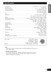
.... Use this unit when an audio signal is input. Bass boost ...Frequency: 40 Hz to 120 Hz Level: 0 / 6 / 9 / 12 dB Gain control ...RCA: 400 mV to 6.5 V Maximum input level / impedance ...RCA: 6.5 V / 22 kΩ Power output 500 W RMS × 1 channel (at 4 Ω and 1% THD+N) 1 000 W RMS × 1 channel (at continuous power, 4 Ω) Average current drawn* ...12 A (4 Ω for one channel) 26 A (2 Ω for one channel) 34 A (1 Ω for one channel) Fuse ...40 A × 4 Dimensions ...381...
.... Use this unit when an audio signal is input. Bass boost ...Frequency: 40 Hz to 120 Hz Level: 0 / 6 / 9 / 12 dB Gain control ...RCA: 400 mV to 6.5 V Maximum input level / impedance ...RCA: 6.5 V / 22 kΩ Power output 500 W RMS × 1 channel (at 4 Ω and 1% THD+N) 1 000 W RMS × 1 channel (at continuous power, 4 Ω) Average current drawn* ...12 A (4 Ω for one channel) 26 A (2 Ω for one channel) 34 A (1 Ω for one channel) Fuse ...40 A × 4 Dimensions ...381...

Owner's Manual
Page 56
... droits de reproduction et de traduction réservés. TEL: (800) 421-1404 PIONEER EUROPE NV Haven 1087, Keetberglaan 1, B-9120 Melsele, Belgium TEL: (0) 3/570.05.11 PIONEER ELECTRONICS ASIACENTRE PTE. PIONEER CORPORATION 4-1, MEGURO 1-CHOME, MEGURO-KU, TOKYO 153-8654, JAPAN PIONEER ELECTRONICS (USA) INC. LTD. 178-184 Boundary Road, Braeside, Victoria 3195, Australia TEL...
... droits de reproduction et de traduction réservés. TEL: (800) 421-1404 PIONEER EUROPE NV Haven 1087, Keetberglaan 1, B-9120 Melsele, Belgium TEL: (0) 3/570.05.11 PIONEER ELECTRONICS ASIACENTRE PTE. PIONEER CORPORATION 4-1, MEGURO 1-CHOME, MEGURO-KU, TOKYO 153-8654, JAPAN PIONEER ELECTRONICS (USA) INC. LTD. 178-184 Boundary Road, Braeside, Victoria 3195, Australia TEL...


